IFM Electronic ecomot300 Supplementary Device Manual
Interface canopen in the as-i controllere
Hide thumbs
Also See for ecomot300:
- Operating instructions manual (11 pages) ,
- Device manual (35 pages)

Related Manuals for IFM Electronic ecomot300


Summary of Contents for IFM Electronic ecomot300
- Page 1 Supplementary device manual Interface CANopen in the AS-i controllerE AC1331 AC1332 Firmware version RTS 2.x Target from 15 ® for CoDeSys from version 2.3 English...
- Page 2 Supplementary device manual Interface CANopen in the AS-i controllerE Contents As on: 28 January 2011 © All rights reserved by ifm electronic gmbh. No part of this manual may be reproduced and used without the consent of ifm electronic gmbh.
-
Page 3: Table Of Contents
Supplementary device manual Interface CANopen in the AS-i controllerE Contents Contents On this manual ..........................7 What do the symbols and formats mean? ................. 7 What devices are described in this manual? ..............8 How is this manual structured? ..................8 Overview: where is what? .................... - Page 4 Supplementary device manual Interface CANopen in the AS-i controllerE Contents Module 4 – digital output master 2(A) ..............32 5.3.4 Module 5 – digital input master 1(B) ...............33 5.3.5 Module 6 – digital output master 1(B) ..............34 5.3.6 Module 7 – digital input master 2(B) ..............35 5.3.7 Module 8 –...
- Page 5 Supplementary device manual Interface CANopen in the AS-i controllerE Contents Menu ............................96 Main menu [Quick Setup] ....................96 Main menu [Fieldbus Setup] ....................97 Set-up ............................98 Basic settings of the fieldbus interface ................98 Parameter setting of the controllerE ................99 9.2.1 Parameter setting of slaves in the controllerE ..........99 9.2.2 Parameter setting of the fieldbus interface in the controllerE ......99 Setting and reading of the fieldbus parameters ............101...
- Page 6 Supplementary device manual Interface CANopen in the AS-i controllerE Contents...
-
Page 7: On This Manual
Supplementary device manual Interface CANopen in the AS-i controllerE On this manual What do the symbols and formats mean? On this manual In this chapter we will give you an overview of the following points: What do the symbols and formats mean? ... -
Page 8: What Devices Are Described In This Manual
Supplementary device manual Interface CANopen in the AS-i controllerE On this manual What devices are described in this manual? What devices are described in this manual? This manual describes the AS-i device family controllerE of ifm electronic gmbh. according to AS-i master specification 3.0 (M4) ... -
Page 9: Overview: Where Is What
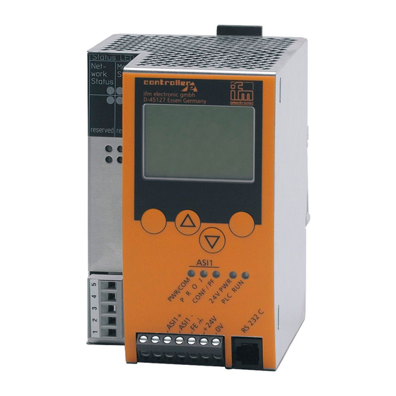
Supplementary device manual Interface CANopen in the AS-i controllerE On this manual Overview: where is what? Overview: where is what? unlocking key for detaching the unit from a metal housing IP 20 DIN rail status LEDs of the fieldbus interface text/graphics display (→... -
Page 10: Safety Instructions
WARNING Property damage or bodily injury when the notes in this manual are not adhered to! ifm electronic assumes no liability for this. ► The acting person must have read and understood the safety instructions and the corresponding chapters in this manual before working on and with this device. -
Page 11: System Requirements
System requirements Information about the device → separate basic instructions of the device manual This manual describes the AS-i controllerE device family of ifm electronic gmbh with the option CANopen fieldbus interface. Information concerning the software → separate basic instructions of the device manual Required accessories Basic functions ... -
Page 12: Getting Started
Supplementary device manual Interface CANopen in the AS-i controllerE Getting started Overview Getting started Overview The chapter General set-up procedure (→ page 13) illustrates the general set-up procedure for the controllerE devices AC1331 / AC1332 by means of 2 flowcharts. Possible error states and the corresponding corrective measures are described in additional tables in this chapter. -
Page 13: General Set-Up Procedure
Supplementary device manual Interface CANopen in the AS-i controllerE Getting started General set-up procedure General set-up procedure START A ddress A S-i slaves via addressing unit Address AS-i slaves automatically (e.g. AC1144) during assembling? ye s Install Har dw ar e: Install Har dw ar e: Power supplies, AS-i network, preaddressed Power supplies, AS-i network, preaddressed... -
Page 14: Troubleshooting (1)
Supplementary device manual Interface CANopen in the AS-i controllerE Getting started General set-up procedure 4.2.1 Troubleshooting (1) Checkpoint Status Possible cause Remedy ► LED [24 V PWR] 24 V voltage supply not ok. Check 24 V voltage supply! ► AS-i voltage supply not ok. Check AS-i voltage supply AS-i! ►... -
Page 15: Troubleshooting (2)
Supplementary device manual Interface CANopen in the AS-i controllerE Getting started General set-up procedure 4.2.2 Troubleshooting (2) Checkpoint Status Possible cause Remedy ► Read the error messages on the display of the controllerE and determine the concerned slave address(es)! ► One of the connected AS-i slaves Read in the corresponding red flashing... -
Page 16: Fieldbus Setup (Overview)
Supplementary device manual Interface CANopen in the AS-i controllerE Getting started Fieldbus setup (overview) Fieldbus setup (overview) Start fieldbus setup Hardware installation Connect controllerE to the CANopen network. Fieldbus setup ► Set the node ID ► Set the baud rate ►... -
Page 17: Connect A Schneider Premium Controller Via Canopen
Supplementary device manual Interface CANopen in the AS-i controllerE Getting started Connect a Schneider Premium controller via CANopen Connect a Schneider Premium controller via CANopen Step 1 – Start software PL7 Junior and create a new project 4.4.1 ► Start the software on the PC ►... -
Page 18: Step 2 - Configure The Hardware
Supplementary device manual Interface CANopen in the AS-i controllerE Getting started Connect a Schneider Premium controller via CANopen Step 2 – Configure the hardware 4.4.2 If the EDS file is already registered, skip step 2 and continue with step 3. ►... - Page 19 Supplementary device manual Interface CANopen in the AS-i controllerE Getting started Connect a Schneider Premium controller via CANopen ► In the pull-down menu for the PCMCIA module select the CANopen master module [TSX CPP 100-110 CAN OPEN PCMCIA CARD] ► Start the Hilscher configuration software by clicking on the symbol [SyCon tool]...
-
Page 20: Step 3 - Sycon Canopen Configuration
Supplementary device manual Interface CANopen in the AS-i controllerE Getting started Connect a Schneider Premium controller via CANopen Step 3 – SyCon CANopen configuration 4.4.3 ► Click on the symbol [New] ( figure) select the menu [File] > [New] to create a new project. ►... - Page 21 Supplementary device manual Interface CANopen in the AS-i controllerE Getting started Connect a Schneider Premium controller via CANopen ► Click on the symbol [Insert Node] to insert a CANopen node in the configuration. > The shape of the cursor changes to [N] ►...
- Page 22 Supplementary device manual Interface CANopen in the AS-i controllerE Getting started Connect a Schneider Premium controller via CANopen ► In the default setting 4 PDOs of input data and 4 PDOs of output data are configured with a data length of 8 bytes each. This is the so-called [Predefined Connection Setup]...
-
Page 23: Step 4 - Integrate The Sycon Configuration File By Means Of Pl7 Junior
Supplementary device manual Interface CANopen in the AS-i controllerE Getting started Connect a Schneider Premium controller via CANopen Step 4 – Integrate the SyCon configuration file by means of PL7 Junior 4.4.4 ► Click on the symbol [Select Database] ( figure) and select the saved SyCon configuration file... -
Page 24: Step 5 - Download Of The Created Configuration To The Premium Plc
Supplementary device manual Interface CANopen in the AS-i controllerE Getting started Connect a Schneider Premium controller via CANopen Step 5 – Download of the created configuration to the Premium PLC 4.4.5 ► Connect the configuration PC to the controller ► Click on the symbol [Transfer] (... -
Page 25: Step 6 - Check The Data Exchange Between Premium Plc And Controllere
Supplementary device manual Interface CANopen in the AS-i controllerE Getting started Connect a Schneider Premium controller via CANopen Step 6 – Check the data exchange between Premium PLC and controllerE 4.4.6 Can Premium PLC and controllerE data be exchanged? ► Mark the directory [Animation Tables] ►... -
Page 26: Function
Supplementary device manual Interface CANopen in the AS-i controllerE Function Data management Function Basic functions separate basic instructions of the device manual Data management The controllerE consists of different units: text/graphics display AS-i master 1 CANopen fieldbus interface central (AS-i master 2) processing unit... -
Page 27: Connection Of The Hardware
Supplementary device manual Interface CANopen in the AS-i controllerE Function The CANopen fieldbus interface 5.2.1 Connection of the hardware The controllerE devices AC1331 and AC1332 feature 5-pole Combicon connectors with screw terminals for connection of the devices to CANopen. Connection of the supply voltage to the terminals 1 (V-) and 5 (V+) is optional. -
Page 28: The Dual-Ported Ram
Supplementary device manual Interface CANopen in the AS-i controllerE Function The CANopen fieldbus interface 5.2.2 The dual-ported RAM In order to understand the settings of the fieldbus interface it is important to understand the function of the dual-ported RAM. The dual-ported RAM, in the following called DP-RAM, is a memory range which constitutes the interface between the controllerE data and the data of the fieldbus interface. -
Page 29: The Fieldbus Modules
Supplementary device manual Interface CANopen in the AS-i controllerE Function The fieldbus modules The fieldbus modules As with all controllerE devices with fieldbus interface, the information to be exchanged is subdivided into logical blocks: the so-called fieldbus modules - in the following called modules. These modules often have a variable size (data length). -
Page 30: Module 1 - Digital Input Master 1(A)
Supplementary device manual Interface CANopen in the AS-i controllerE Function The fieldbus modules Module 1 – digital input master 1(A) 5.3.1 Binary input data of the digital single or A slave of AS-i master 1 Data content Data from the controllerE to the fieldbus interface Direction of data Value range 0…16 [bytes]... -
Page 31: Module 2 - Digital Output Master 1(A)
Supplementary device manual Interface CANopen in the AS-i controllerE Function The fieldbus modules Module 2 – digital output master 1(A) 5.3.2 Binary output data of the digital single or A slaves of AS-i master 1 Data content Data from the fieldbus interface to the controller Direction of data Value range 0…16 [bytes]... -
Page 32: Module 3 - Digital Input Master 2(A)
Supplementary device manual Interface CANopen in the AS-i controllerE Function The fieldbus modules Module 3 – digital input master 2(A) 5.3.3 Binary input data of the digital single or A slave of AS-i master 2 Data content Data from the controllerE to the fieldbus interface Direction of data Value range 0…16 [bytes]... -
Page 33: Module 5 - Digital Input Master 1(B)
Supplementary device manual Interface CANopen in the AS-i controllerE Function The fieldbus modules Module 5 – digital input master 1(B) 5.3.5 Binary input data of the digital B slaves of AS-i master 1 Data content Data from the controllerE to the fieldbus interface Direction of data Value range 0…16 [bytes]... -
Page 34: Module 6 - Digital Output Master 1(B)
Supplementary device manual Interface CANopen in the AS-i controllerE Function The fieldbus modules Module 6 – digital output master 1(B) 5.3.6 Binary output data of the digital B slaves of AS-i master 1 Data content Data from the fieldbus interface to the controllerE Direction of data Value range 0…16 [bytes]... -
Page 35: Module 7 - Digital Input Master 2(B)
Supplementary device manual Interface CANopen in the AS-i controllerE Function The fieldbus modules Module 7 – digital input master 2(B) 5.3.7 Binary input data of the digital B slaves of AS-i master 2 Data content Data from the controllerE to the fieldbus interface Direction of data Value range 0…16 [bytes]... -
Page 36: Module 9 - Analogue Multiplexed Input
Supplementary device manual Interface CANopen in the AS-i controllerE Function The fieldbus modules Module 9 – analogue multiplexed input 5.3.10 Analogue input data of the slaves of the AS-i masters 1 + 2 Data content The data of analogue input slaves with the following AS-i slave addresses can be read directly Note via the modules 14 (master 1) (→... -
Page 37: Example For Module 9
Supplementary device manual Interface CANopen in the AS-i controllerE Function The fieldbus modules Example for module 9 Task: Channel 2 (according to the labelling on the unit) of the analogue input slave with the AS-i address 21 on master 2 is to be read. Solution: Requirement: Word... -
Page 38: Module 10 - Analogue Multiplexed Output
Supplementary device manual Interface CANopen in the AS-i controllerE Function The fieldbus modules Module 10 – analogue multiplexed output 5.3.11 Analogue output data of the slaves of the AS-i masters 1 + 2 Data content The data of analogue output slaves with the following AS-i slave addresses can be written Note directly via the modules 15 (master 1) (→... -
Page 39: Example For Module 10
Supplementary device manual Interface CANopen in the AS-i controllerE Function The fieldbus modules Example for module 10 Task: Channel 4 (according to the labelling on the unit) of the analogue output slave with the AS-i address 12 on master 1 is to be set to the value 5000. Solution: Requirement: Word... -
Page 40: Module 11 - Fieldbus Data Command Channel
Supplementary device manual Interface CANopen in the AS-i controllerE Function The fieldbus modules Module 11 – fieldbus data command channel 5.3.12 Command channel data of the AS-i masters 1 + 2 Data content For a detailed description of the handling of the fieldbus data command channel and the Note different commands →... -
Page 41: Module 12 - Fieldbus Data Plc Input
Supplementary device manual Interface CANopen in the AS-i controllerE Function The fieldbus modules Module 12 – fieldbus data PLC input 5.3.13 Up to 128 bytes freely definable data Data content Data from the fieldbus interface to the controllerE Direction of data Value range 0…128 [bytes] Module settings... -
Page 42: Module 13 - Fieldbus Data Plc Output
Supplementary device manual Interface CANopen in the AS-i controllerE Function The fieldbus modules Module 13 – fieldbus data PLC output 5.3.14 Up to 128 bytes freely definable data Data content Data from the controllerE to the fieldbus interface Direction of data Value range 0…128 [bytes] Module settings... -
Page 43: Module 14 - Analogue Input Master 1
Supplementary device manual Interface CANopen in the AS-i controllerE Function The fieldbus modules Module 14 – analogue input master 1 5.3.15 Analogue input data of the analogue slaves to AS-I master 1 Data content With module 14 the data of the analogue input slaves on AS-i master 1 with the following AS-i Note slave addresses can be directly read: ... -
Page 44: Module 14 - Table For Input Data For 4 Channels Per Slave
Supplementary device manual Interface CANopen in the AS-i controllerE Function The fieldbus modules Module 14 - table for input data for 4 channels per slave For setting 4 channels per slave Value range Sum of words Word no. AS-i addr. Channel AS-i addr. - Page 45 Supplementary device manual Interface CANopen in the AS-i controllerE Function The fieldbus modules For setting 4 channels per slave Value range Sum of words Word no. AS-i addr. Channel AS-i addr. Channel...
- Page 46 Supplementary device manual Interface CANopen in the AS-i controllerE Function The fieldbus modules For setting 4 channels per slave Value range Sum of words Word no. AS-i addr. Channel AS-i addr. Channel...
-
Page 47: Module 14 - Table For Input Data For 1 Channel Per Slave
Supplementary device manual Interface CANopen in the AS-i controllerE Function The fieldbus modules Module 14 - table for input data for 1 channel per slave For setting 1 channel per slave Value range Sum of words Word no. AS-i addr. Channel 1(A) 2(A) - Page 48 Supplementary device manual Interface CANopen in the AS-i controllerE Function The fieldbus modules For setting 1 channel per slave Value range Sum of words Word no. AS-i addr. Channel 24(A) 25(A) 26(A) 27(A) 28(A) 29(A) 30(A) 31(A)
-
Page 49: Module 15 - Analogue Output Master 1
Supplementary device manual Interface CANopen in the AS-i controllerE Function The fieldbus modules Module 15 – analogue output master 1 5.3.16 Analogue output data of the analogue slaves to AS-i master 1 Data content With module 15 the data of the analogue input slaves on AS-i master 1 with the following AS-i Note slave addresses can be directly written: ... -
Page 50: Module 15 - Table For Output Data For 4 Channels Per Slave
Supplementary device manual Interface CANopen in the AS-i controllerE Function The fieldbus modules Module 15 – table for output data for 4 channels per slave For setting 4 channels per slave Value range Sum of words Word no. AS-i addr. Channel AS-i addr. - Page 51 Supplementary device manual Interface CANopen in the AS-i controllerE Function The fieldbus modules For setting 4 channels per slave Value range Sum of words Word no. AS-i addr. Channel AS-i addr. Channel 0 (60) 1 (61) 1 (17) 4 (124) 2 (62) 3 (63) 4 (64)
- Page 52 Supplementary device manual Interface CANopen in the AS-i controllerE Function The fieldbus modules For setting 4 channels per slave Value range Sum of words Word no. AS-i addr. Channel AS-i addr. Channel 36 (96) 37 (97) 10 (17) 40 (124) 38 (98) 39 (99) 40 (100)
-
Page 53: Module 15 - Table For Output Data For 1 Channel Per Slave
Supplementary device manual Interface CANopen in the AS-i controllerE Function The fieldbus modules Module 15 – table for output data for 1 channel per slave For setting 1 channel per slave Value range Sum of words Word no. AS-i addr. Channel 1(A) 2(A) - Page 54 Supplementary device manual Interface CANopen in the AS-i controllerE Function The fieldbus modules For setting 1 channel per slave Value range Sum of words Word no. AS-i addr. Channel 16 (46) 24(A) 9 (17) 18 (62) 17 (47) 18 (48) 25(A) 10 (17) 20 (62)
-
Page 55: Module 16 - Analogue Input Master 2
Supplementary device manual Interface CANopen in the AS-i controllerE Function The fieldbus modules Module 16 – analogue input master 2 5.3.17 Analogue input data of the analogue slaves to AS-master 2 Data content With module 16 the data of the analogue input slaves on AS-i master 2 with the AS-i slave Note addresses can be directly read. -
Page 56: Module 17 - Analogue Output Master 2
Supplementary device manual Interface CANopen in the AS-i controllerE Function The fieldbus modules Module 17 – analogue output master 2 5.3.18 Analogue output data of the analogue slaves to AS-i master 2 Data content With module 17 the data of the analogue input slaves on AS-i master 2 with the following AS-i Note slave addresses can be directly written: ... -
Page 57: Module 18 - Fieldbus Diagnostic Data
Supplementary device manual Interface CANopen in the AS-i controllerE Function The fieldbus modules Module 18 – fieldbus diagnostic data 5.3.19 Diagnostic data of the AS-i masters 1 and 2 Data content Data from the controllerE to the fieldbus interface Direction of data Value range 0…2 Module settings... -
Page 58: Module 19 - Host Command Channel
Supplementary device manual Interface CANopen in the AS-i controllerE Function The fieldbus modules Module 19 – host command channel 5.3.20 Host command channel data of the AS-i masters 1 + 2 Data content For a detailed description of the handling of the host command channel and the different Note commands ... -
Page 59: The Host Command Channel
Supplementary device manual Interface CANopen in the AS-i controllerE Function The fieldbus modules 5.3.21 The host command channel The module 19 (→ page 58) contains an extended command channel which can have a length of 5 or 18 words. A PLC with CANopen interface can be used as host system. The commands are always triggered by the host by a corresponding entry in its output data range. - Page 60 Supplementary device manual Interface CANopen in the AS-i controllerE Function The fieldbus modules NOTE If a command is to be executed, the user ID must be changed! Changing the command number alone does not start the execution. If a command is to be executed several times, the user ID must be changed accordingly, e.g. by counting up.
-
Page 61: Host Commands
Supplementary device manual Interface CANopen in the AS-i controllerE Function The fieldbus modules 5.3.22 Host commands Command number Description decimal hexadecimal execute no command write parameters to a connected AS-i slave (change current slave parameters) adopt and save currently connected AS-i slaves in the configuration change the list of the projected AS-i slaves (LPS) set the operating mode of the AS-i master readdress a connected AS-i slave... -
Page 62: Examples For The Host Command Channel
Supplementary device manual Interface CANopen in the AS-i controllerE Function The fieldbus modules Examples for the host command channel (here, values are indicated in hexadecimal representation) Command 0, 16#0 – execute no command Request from the host >> controllerE: Word no. M = 0 user ID command number = 00... - Page 63 Supplementary device manual Interface CANopen in the AS-i controllerE Function The fieldbus modules Command 1, 16#1 – write parameters to a connected AS-i slave (change current slave parameters) Request from the host >> controllerE: Word no. user ID command number = 1 reserved = 0 reserved = 0 16#00...
- Page 64 Supplementary device manual Interface CANopen in the AS-i controllerE Function The fieldbus modules Command 3, 16#3 – adopt and save currently connected AS-i slaves in the configuration Note: This command can only be executed without error when the addressed AS-i master is in the projection mode.
- Page 65 Supplementary device manual Interface CANopen in the AS-i controllerE Function The fieldbus modules Command 4, 16#4 – change the list of the projected AS-i slaves (LPS) Request from the host >> controllerE: Word no. user ID command number = 04 reserved = 00 reserved = 00 15(A)
- Page 66 Supplementary device manual Interface CANopen in the AS-i controllerE Function The fieldbus modules Command 5, 16#5 – set the operating mode of the AS-i master Request from the host >> controllerE: Word no. user ID command number = 05 reserved = 00 reserved = 00 16#00 activate the projection mode = 16#01...
- Page 67 Supplementary device manual Interface CANopen in the AS-i controllerE Function The fieldbus modules Command 6, 16#6 – readdress a connected AS-i slave Request from the host >> controllerE: Word no. user ID command number = 06 reserved = 00 reserved = 00 16#00 old slave address 9B = 16#29 16#00...
- Page 68 Supplementary device manual Interface CANopen in the AS-i controllerE Function The fieldbus modules Commando 7, 16#7 – set the auto address mode of the AS-i master Request from the host >> controllerE: Word no. user ID command number = 07 reserved = 00 reserved = 00 automatic addressing activated...
- Page 69 Supplementary device manual Interface CANopen in the AS-i controllerE Function The fieldbus modules Command 9, 16#9 – change the extended ID code 1 in the connected AS-i slave Request from the host >> controllerE: Word no. user ID command number = 09 reserved = 00 reserved = 00 16#00...
- Page 70 Supplementary device manual Interface CANopen in the AS-i controllerE Function The fieldbus modules Commands 10...20, 16#0A...16#14 – force analogue data transmission directly to/from 3 AS-i slaves respectively With these commands the analogue input or output data of 3 slaves can be overwritten. The commands are assigned to 3 slave addresses each: Command number Slaves...
- Page 71 Supplementary device manual Interface CANopen in the AS-i controllerE Function The fieldbus modules 7th word: 16#0055 overflow and valid bits for AS-i slave 1: O3 = 0, V3 = 1, O2 = 0, V2 = 1, O1 = 0, V1 = 1, O0 = 0, V0 = 1 8th word: 16#2009 output data AS-i slave 2, channel 0 9th word: 16#2202...
- Page 72 Supplementary device manual Interface CANopen in the AS-i controllerE Function The fieldbus modules Example: 1st word: 16#0901 reflected command number A, user ID changes to 1 2nd word: 16#0000 (reserved) 3rd word: 16#3169 (slave 1 is a 4-channel input slave) input data AS-i slave 1, channel 0 4th word: 16#2202 input data AS-i slave 1, channel 1...
- Page 73 Supplementary device manual Interface CANopen in the AS-i controllerE Function The fieldbus modules Command 28, 16#1C – deactivation of the slave reset when changing to the protected mode When changing from the projection mode to the protected mode, all slaves are normally briefly reset (reset).
- Page 74 Supplementary device manual Interface CANopen in the AS-i controllerE Function The fieldbus modules Command 31, 16#1F – one-time execution of the "Extended safety monitor protocol" in the "Safety at Work" monitor. Request from the host >> controllerE: Word no. user ID command number = 21 (16#1F) reserved = 00 reserved = 00...
- Page 75 Supplementary device manual Interface CANopen in the AS-i controllerE Function The fieldbus modules data call 1 data call 0 Meaning protective operation, everything OK (not available, not configured or depending output circuits are displayed as [OK]) protective operation, output circuit 1 off. protective operation, output circuit 2 off.
- Page 76 Supplementary device manual Interface CANopen in the AS-i controllerE Function The fieldbus modules "Safety at Work" monitor has triggered: 1st word: 16#071F reflected command number 1F, user ID changes to 7 2nd word: 16#0000 (reserved) 3rd word: 16#001E reflected subcommand 0 and AS-i slave address 30 4th word: 16#2211 16#2xxx: output circuit 1 red: 16#x2xx: invalid, see word 5;...
- Page 77 Supplementary device manual Interface CANopen in the AS-i controllerE Function The fieldbus modules Command 21, 16#15 – read ID string of an AS-i slave with profile S-7.4 Request from the host >> controllerE: Word no. R = 0 R = 0 user ID command number = 21 (16#15) AS-i slave address...
- Page 78 Supplementary device manual Interface CANopen in the AS-i controllerE Function The fieldbus modules Mux field = number of multiplexed data words Length: 3 bits Permitted values: 0…3 Meaning: number = value in "Mux field" +1 E type = characterises the slave as regards functionality and data structure Length: 5 bits Permitted values: 0...31 Meaning:...
- Page 79 Supplementary device manual Interface CANopen in the AS-i controllerE Function The fieldbus modules Possible error codes: faulty S-7.4 protocol sequence 16#0C S-7.4 protocol aborted (timeout) 16#0D invalid AS-i slave address for the S-7.4 protocol (e.g. B slaves) 16#0E AS-i slave has terminated the S-7.4 string 16#0F AS-i S-7.4 no longer connected (no longer in LAS) 16#10...
- Page 80 Supplementary device manual Interface CANopen in the AS-i controllerE Function The fieldbus modules Command 21, 16#33 – read diagnosis string of an AS-i slave with profile S-7.4 Request from the host >> controllerE: Word no. S = 0 user ID command number = 33 (16#21) AS-i slave address length to be sent (here = 0)
- Page 81 Supplementary device manual Interface CANopen in the AS-i controllerE Function The fieldbus modules Command 34, 16#22 – read parameter string of an AS-i slave with profile S-7.4 Request from the host >> controllerE: Word no. S = 0 user ID command number = 34 (16#22) AS-i slave address length to be sent (here = 0)
- Page 82 Supplementary device manual Interface CANopen in the AS-i controllerE Function The fieldbus modules Command 35, 16#23 – write parameter string of an AS-i slave with profile S-7.4 Request from the host >> controllerE: Word no. user ID command number = 35 (16#23) AS-i slave address length to be sent parameter string 1...
- Page 83 Supplementary device manual Interface CANopen in the AS-i controllerE Function The fieldbus modules Command 50, 16#32 – read current configuration AS-i slaves 0(A)…15(A) Request from the host >> controllerE: Word no. user ID command number = 50 (16#32) reserved = 00 reserved = 00 not used not used...
- Page 84 Supplementary device manual Interface CANopen in the AS-i controllerE Function The fieldbus modules Command 54, 16#36 – read current parameters of a connected AS-i slave Request from the host >> controllerE: Word no. user ID command number = 54 (16#36) 2…18 not used not used...
- Page 85 Supplementary device manual Interface CANopen in the AS-i controllerE Function The fieldbus modules Command 55, 16#37 - read current AS-i slave lists Request from the host >> controllerE: Word no. user ID command number = 55 (16#37) not used not used 2...18 Example: 1st word: 16#0737...
- Page 86 Supplementary device manual Interface CANopen in the AS-i controllerE Function The fieldbus modules 12th word: 16#0001 LPF slaves 16(A) to 31(A), here: peripheral fault on slave 16 13th word: 16#0002 LPF slaves (0B) to 15B; here: peripheral fault on slave 1B 14th word: 16#8000 LPF slaves 16B to 31B;...
- Page 87 Supplementary device manual Interface CANopen in the AS-i controllerE Function The fieldbus modules Command 56, 16#38 – read projected configuration AS-i slaves 1(A)…15(A) Request from the host >> controllerE: Word no. user ID command number = 56 (16#38) 2…18 not used not used Example: 1st word: 16#0238...
- Page 88 Supplementary device manual Interface CANopen in the AS-i controllerE Function The fieldbus modules Command 96, 16#60: "save data in the flash memory of the controllerE in a non-volatile manner" Request from the host >> controllerE: Word no. user ID command number = 96 (16#60) reserved = 00 reserved = 00 16#00...
- Page 89 Supplementary device manual Interface CANopen in the AS-i controllerE Function The fieldbus modules Command 97, 16#61 – carry out various settings in the controllerE Request from the host >> controllerE: Word no. user ID command number = 97 (16#61) reserved = 00 reserved = 00 16#00 command number...
- Page 90 Supplementary device manual Interface CANopen in the AS-i controllerE Function The fieldbus modules Command 102, 16#66 – retrieve the status of the controllerE display Request from the host >> controllerE: Word no. user ID command number = 102 (16#66) reserved = 00 reserved = 00 16#00 command number = 16#01...
- Page 91 Supplementary device manual Interface CANopen in the AS-i controllerE Function The fieldbus modules Command 105, 16#69 – read the device properties of the controllerE Request from the host >> controllerE: Word no. user ID command number = 105 (16#69) not used not used 2...18 Example:...
- Page 92 Supplementary device manual Interface CANopen in the AS-i controllerE Function The fieldbus modules 5th word: 16#0002 (flash memory type) 6th word: 16#1000 (hardware version) 7th word: 16#0002 (1st part of the RTS firmware version, here: 02.218B) version number 02.xxxx 8th word: 16#218B (2nd part of the RTS firmware version, here: 02.218B) release number xx.218B 9th word: 16#0000 (1st part of the AS-i master 1 firmware version, here: 0.238A) version number 0.xxxx...
-
Page 93: Special Settings
The source code for the required driver project has to be requested separately from ifm electronic gmbh. Possible setting values:... -
Page 94: Operating And Display Elements
Supplementary device manual Interface CANopen in the AS-i controllerE Operating and display elements Status LEDs on the network connection Operating and display elements Diagnostic LEDs → separate basic device manual Key functions → separate basic device manual Display basic functions → separate basic device manual Status LEDs on the network connection 4 status LEDs on the controllerE inform about the status of the CANopen interface and the systems connected to it:... -
Page 95: Led [Power]
Supplementary device manual Interface CANopen in the AS-i controllerE Operating and display elements Display 7.1.4 LED [Power] LED status Description no supply voltage permanently green supply voltage present Display Display basic functions → separate basic device manual... -
Page 96: Menu
Supplementary device manual Interface CANopen in the AS-i controllerE Menu Main menu [Quick Setup] Menu NOTE All menu texts in this manual are in English. Basic functions separate basic instructions of the device manual Main menu [Quick Setup] Setting and reading of the fieldbus parameters (password level 1 required). Details ... -
Page 97: Main Menu [Fieldbus Setup]
Supplementary device manual Interface CANopen in the AS-i controllerE Menu Main menu [Fieldbus Setup] Main menu [Fieldbus Setup] Setting and reading of the fieldbus parameters (password level1 required). Details page 101, chapter „Setting and reading of the fieldbus parameters“ Menu tree Explanation Fieldbus setup... -
Page 98: Set-Up
Supplementary device manual Interface CANopen in the AS-i controllerE Set-up Basic settings of the fieldbus interface Set-up This chapter shows you how to get the CANopen interface started quickly Basic settings of the fieldbus interface NOTE The settings on the controllerE must meet the following conditions: ... -
Page 99: Parameter Setting Of The Controllere
Supplementary device manual Interface CANopen in the AS-i controllerE Set-up Parameter setting of the controllerE Parameter setting of the controllerE 9.2.1 Parameter setting of slaves in the controllerE Set the parameters of the slaves in the AS-i controllerE as described in the basic device manual. 9.2.2 Parameter setting of the fieldbus interface in the controllerE ►... - Page 100 Supplementary device manual Interface CANopen in the AS-i controllerE Set-up Parameter setting of the controllerE Fieldbus Baud rate > Display of the current fieldbus baud rate 250 kbaud ► Use [▲] / [▼] to scroll to the requested baud rate ►...
-
Page 101: Setting And Reading Of The Fieldbus Parameters
Supplementary device manual Interface CANopen in the AS-i controllerE Set-up Setting and reading of the fieldbus parameters Setting and reading of the fieldbus parameters Continued from the preceding chapter Digital inputs > Shows that the fieldbus module 1 (digital input master Master 1 (A) 1(A)) with a length of 16 bytes is activated ►... - Page 102 Supplementary device manual Interface CANopen in the AS-i controllerE Set-up Setting and reading of the fieldbus parameters Digital outputs > Shows that the fieldbus module 6 (digital output Master 1 (B) master 1B) with a length of 16 bytes is activated. ►...
- Page 103 Supplementary device manual Interface CANopen in the AS-i controllerE Set-up Setting and reading of the fieldbus parameters Fieldbus data > Shows that the fieldbus module 11 (fieldbus data Command channel command channel) is activated. ► Change the setting with [▲] / [▼]. ►...
- Page 104 Supplementary device manual Interface CANopen in the AS-i controllerE Set-up Setting and reading of the fieldbus parameters Analog input > Shows that the fieldbus module 16 (analogue input Master 2 master 2) is not activated. ► Change the setting with [▲] / [▼]. ►...
-
Page 105: Store System Parameters
Supplementary device manual Interface CANopen in the AS-i controllerE Set-up Store system parameters Store system parameters Basic device manual... -
Page 106: Terms, Abbreviations
Supplementary device manual Interface CANopen in the AS-i controllerE Terms, abbreviations Terms, abbreviations Slave with an A or B being appended to its address number and which may A/B slave therefore be present twice on the master. Address This is the "name" of the bus participant. All participants need a unique address so that the signals can be exchanged without problem. - Page 107 Supplementary device manual Interface CANopen in the AS-i controllerE Terms, abbreviations Ethernet Ethernet is a widely used, manufacturer-independent technnology which enables transmission of data in the network. Ethernet belongs to the family of so-called "optimum data transmission" on a non exclusive transmission medium. The concept was developed in 1972 and specified as IEEE 802.3 in 1985.
- Page 108 Supplementary device manual Interface CANopen in the AS-i controllerE Terms, abbreviations List of Projected Slaves In this slave list the controllerE enters the slaves projected for this AS-i master. MAC ID MAC = Manufacturer‘s Address Code = manufacturer's serial number ID = Identifier Every network card has a MAC address, a clearly defined worldwide unique numerical code, more or less a kind of serial number.
- Page 109 Supplementary device manual Interface CANopen in the AS-i controllerE Terms, abbreviations Polling to poll = to count votes The controller master fetches the data from every participant in the system successively: Master calls participant 1. Participant 1 replies with its current data (actual values). Master transfers more data (target values) to participant 1, if needed.
- Page 110 Supplementary device manual Interface CANopen in the AS-i controllerE Terms, abbreviations SELV SELV = Safety Extra Low Voltage Active parts of safety extra low voltage circuits must neither be connected to ground nor to protective wires of other circuits. They must be safely separated from active parts with higher voltage.
-
Page 111: Index
Supplementary device manual Interface CANopen in the AS-i controllerE Index Index NOTE nn-n The indication of the page where you can find some information about the keyword is written in normal characters. ii-i The indication of the page where the keyword is detailed is written in italics. A/B slave ................
Need help?
Do you have a question about the ecomot300 and is the answer not in the manual?
Questions and answers