Table of Contents
Advertisement
Advertisement
Table of Contents

Related Manuals for IFM Electronic Ecomat 300 AC1154


Summary of Contents for IFM Electronic Ecomat 300 AC1154
- Page 1 Operating instructions Addressing unit AC1154...
-
Page 2: Table Of Contents
Inhalt 1 Functions and features ����������������������������������������������������������������������������������������3 2 Safety instructions �����������������������������������������������������������������������������������������������3 3 Introduction to the AS-interface version 2�1 ��������������������������������������������������������3 4 Structure of the addressing unit ��������������������������������������������������������������������������4 5 Operating modes �������������������������������������������������������������������������������������������������7 6 Addressing mode �������������������������������������������������������������������������������������������������8 6�1 Addressing of slaves with IR interface ���������������������������������������������������������10 6�2 Other operating modes ��������������������������������������������������������������������������������... -
Page 3: Functions And Features
Functions and features The protection of operating personnel and system against possible danger is not guaranteed if the sub-assembly is not operated in accordance with its intended use� The unit must be operated by qualified staff in accordance with these operating instructions�... -
Page 4: Structure Of The Addressing Unit
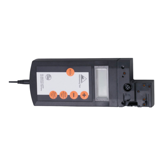
This is sufficient to address 32 slaves� In normal operation, address 0 is not per- mitted, thus allowing 31 AS-i slaves to be operated� The address range is doubled by using the data bit D3 as sixth bit for addressing, which enables the addressing of 62 slaves�... - Page 5 addressing unit needs to be recharged with the battery charger supplied with the unit� The structure of the AC1154 addressing unit is shown in the following figure: � � � � � � � � � � adapter for the connection of AS-interface slaves LC display control panel Write/Set...
- Page 6 Operation with the AS-i power supply is possible but cannot be guaranteed for all topologies� The AS-i master must be switched offline or disconnected� When ope- rated with the AS-i power supply the addressing unit should be connected close to the power supply�...
-
Page 7: Operating Modes
There are five buttons on the control panel which can be used to operate the AC1154 addressing unit� Button Function Read/On • switch on the unit • search for the connected AS-interface slaves • activate the next higher address (in addressing mode only) •... -
Page 8: Addressing Mode
The AC1154 addressing unit supports the following operating modes: Display Operating mode Comments in the LCD: ADDR addressing mode read and write AS-interface slave addresses read ID code ID 1 read and write ID code 1 ID 2 read ID code 2 read IO code DATA read and write data... - Page 9 If several different slaves are connected to the addressing unit, the display swit- ches between conventional A and B slaves (no letters) every 2 seconds� The address of the slave which is to be written next (activated slave) flashes at a frequency of 2 Hz�...
-
Page 10: 6�1 Addressing Of Slaves With Ir Interface
If the corresponding button is pressed once, the display increases or decreases by 1� If the button is held pressed, the addressing unit increments or decrements continuously� To address, use the + or - button to set the new requested address� When one of the two buttons is pressed for the first time, RD is no longer displayed�... -
Page 11: 6�2 Other Operating Modes
This procedure only functions if the slaves have a watchdog function� Slaves without a watchdog must be disconnected from the AS-i voltage for a short time after addressing so that they are detected and activated again by the master� When the slaves are put into service for the first time (address set at the factory is 0) and a SilverLine power supply from ifm is used, the shunt must be put into position 2-3 first before the power supply is switched on�... -
Page 12: 6�3 Read Id Code Or Id Code 2
Read IO code If the Read IO code mode is switched on by pressing the MODE button, the display shows the IO code of the activated slave� It is not possible to change this value� Read and write data This operating mode is for test purposes only� It is not possible to overwrite the output data of the higher-level controller�... -
Page 13: 6�8 Indication Of The Peripheral Fault Flag
A special feature of this operating mode is that the AS-interface supply voltage is not switched off following the read or write operation� Please note that this opera- ting mode places a large load on the battery� First activate the slave to which parameter values are to be written� To switch on the Display and Write Parameters mode, press the MODE button until PARA appears in the display�... -
Page 14: Error Messages
Error messages The addressing unit supports the following error messages: Error Meaning Description code overload AS-interface too high current consumption of the slaves connected to the addressing unit slave not found no slave found at the active address error during programming during programming of the address or of the extended IC code 1 the value could not be permanently stored in the EEPROM of...
Need help?
Do you have a question about the Ecomat 300 AC1154 and is the answer not in the manual?
Questions and answers