Table of Contents
Advertisement
Quick Links
Advertisement
Table of Contents

Related Manuals for IFM Electronic AC2261


Summary of Contents for IFM Electronic AC2261
- Page 1 Operating instructions AS-i module AC2261...
- Page 2 Contents 1 Preliminary note ���������������������������������������������������������������������������������������������������3 1�1 Key to the symbols ����������������������������������������������������������������������������������������3 2 Safety instructions �����������������������������������������������������������������������������������������������3 3 Functions and features ����������������������������������������������������������������������������������������3 4 Operating and display elements ��������������������������������������������������������������������������4 5 Installation������������������������������������������������������������������������������������������������������������4 6 Addressing �����������������������������������������������������������������������������������������������������������4 6�1 Addressing with the AC1154 addressing unit�������������������������������������������������4 7 Electrical connection ��������������������������������������������������������������������������������������������5 8 Operation �������������������������������������������������������������������������������������������������������������6 9 Maintenance, repair and disposal ������������������������������������������������������������������������6...
-
Page 3: Safety Instructions
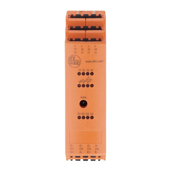
1 Preliminary note Technical data, approvals, accessories and further information at www�ifm�com� 1.1 Key to the symbols ► Instructions Important note Non-compliance may result in malfunction or interference� 2 Safety instructions • Read this document before setting up the product and keep it during the entire service life�... - Page 4 4 Operating and display elements LEDs 1: addressing plug 2: Combicon connector with screw terminals (option) 5 Installation ► Disconnect the system from power before installation� ► Mount the module onto a 35 mm rail or fasten it onto a suitable mounting surface�...
- Page 5 7 Electrical connection The unit must be connected by a qualified electrician� The national and international regulations for the installation of electrical equipment must be adhered to� ► Disconnect power� ► Connect the sensors and actuators to the connection terminals� ►...
- Page 6 8 Operation Check whether the unit operates correctly� Display by LEDs: LED 1 yellow LED lights: input switched LED 2 AS-i green lights: AS-i voltage supply OK LED 2 Fault red lights: AS-i communication error, e�g� slave address 0 LED 2 Fault red flashes: periphery fault, e�g�...
Need help?
Do you have a question about the AC2261 and is the answer not in the manual?
Questions and answers