Table of Contents
Advertisement
Quick Links
Advertisement
Table of Contents

Subscribe to Our Youtube Channel
Related Manuals for BRONKHORST mini CORI-FLOW MI Series


Summary of Contents for BRONKHORST mini CORI-FLOW MI Series
- Page 1 Instruction Manual MI Series Industrial mini CORI-FLOW™ Doc. no.: 9.17.120 rev. A Date: 24-10-2019 ATTENTION Please read this document carefully before installing and operating the product. Not following the guidelines could result in personal injury and/or damage to the equipment.
- Page 2 Check the outside packaging box for damage incurred during shipment. If the box is damaged, then the local carrier must be notified at once regarding his liability, if so required. At the same time a report should be submitted to your Bronkhorst representative.
- Page 3 Bronkhorst® Warranty Bronkhorst® products are warranted against defects in material and workmanship for a period of three years from the date of shipment, provided they are used in accordance with the ordering specifications and not subject to abuse or physical damage.
- Page 4 Bronkhorst® Instruction Manual MI Series Industrial mini CORI-FLOW™ 9.17.120A...
-
Page 5: Table Of Contents
Bronkhorst® Table of contents Introduction ......................7 Scope of this manual . - Page 6 Bronkhorst® 3.7.5 Service port ......................27 Adjusting zero point .
-
Page 7: Introduction
Material Safety Data Sheets of the media to be used in the system (if applicable). Bronkhorst High-Tech B.V. cannot be held liable for any damage resulting from improper or unsafe use, use for other than the intended purpose or use with other media and/or under other conditions than specified on the purchase order. -
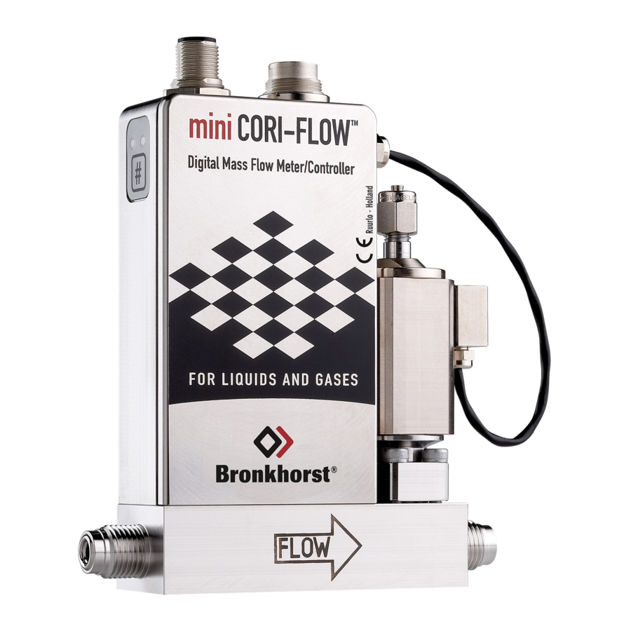
Page 8: Product Overview
The analog output and the digital measured value are scaled accordingly. Switching between ranges can be done via the RS232 interface or the fieldbus interface (if applicable), or with a Bronkhorst® readout and control unit (E-8000, BRIGHT). -
Page 9: Maintenance
The mini CORI-FLOW™ comes with all necessary documentation for basic operation and maintenance. Some parts of this manual refer to other documents, most of which can be downloaded from the Bronkhorst website. Calibration certificates, test certificates and material certificates are part of the scope of delivery or can be provided on request. -
Page 10: Installation
· Operating temperature · Technical properties (see Model key) Do not hesitate to contact your Bronkhorst representative if properties and ordering details do not match. Operating conditions Test pressure Bronkhorst® instruments are pressure tested to at least 1.5 times the specified working process conditions and outboard leak tested to at least 2 * 10 mbar l/s Helium. -
Page 11: Location
· Tighten connections according to the instructions of the supplier of the fittings. Fittings Bronkhorst® mini CORI-FLOW™ meters/controllers can be fitted with different fitting types (e.g. compression or face-seal). For leak tight installation, follow the guidelines of the supplier of the fittings. Special fitting types are available on request. -
Page 12: Electrical Connection
When using other cables, cable wire diameters must be sufficient to carry the supply current, and voltage loss must be kept as low as possible. When in doubt, contact your Bronkhorst representative. When connecting the product to other devices, be sure that the integrity of the shielding is not affected; always use shielded cabling for signals and communication and do not use unshielded wire terminals. -
Page 13: Analog/Rs232
Bronkhorst® To ensure proper shielding, connect the cable shielding with the glands before re-installing them to the instrument housing. For instruments with plastic cable glands, use the supplied clamps to connect the shielding to the metal base plate of the wiring terminal box. -
Page 14: Ethercat/Profinet
Optional fieldbus interface FLOW-BUS FLOW-BUS is a Bronkhorst® designed fieldbus, based on RS485 technology, for digital communication between devices, offering the possibility of host-control by a Windows computer. Characteristics: · Baud rate 187500 (default) or 400000 Baud · +15…24 Vdc supply voltage ·... - Page 15 Bronkhorst® PROFIBUS DP PROFIBUS DP is a 2-wire, RS485-based industrial data communication standard (fieldbus) which allows automation components (e.g. sensors, actuators and controllers) to exchange information. Consult Instruction manual PROFIBUS DP interface (document no. 9.17.025) for more information about setting up a PROFIBUS DP network.
-
Page 16: Operation
Bronkhorst® Operation After correct installation and taking all necessary safety precautions, the mini CORI-FLOW™ can be used to measure and/or control the required flow rates. Powering up and powering down · It is recommended to turn on power before applying fluid pressure and to switch off power only after relieving fluid pressure. -
Page 17: Communication
Bronkhorst® · To avoid simultaneous heating and cooling of different parts of the instrument, make sure the ambient temperature is as stable and evenly distributed across the environment as possible. · Avoid temperature shocks; heating or cooling should amount to no more than 1 °C per second. -
Page 18: Digital Rs232 Operation
The instrument can always be operated via RS232 through the micro USB service connection in the wiring terminal box, even if it is configured for RS485 operation. Connecting the device with a micro USB to USB2.0 adapter cable to a Windows computer enables RS232 operation with the free Bronkhorst® FlowWare software suite for Windows. See also section Service port. -
Page 19: Software (Dde Applications)
DDE are for example MS-Office, LabVIEW, InTouch and Wizcon. Bronkhorst® software applications 'FlowView' (left) and 'FlowPlot' (right) FlowDDE and other Bronkhorst® applications are available on the support CD or can be downloaded from the product pages on the Bronkhorst website: www.bronkhorst.com/products 3.6.3... - Page 20 PROFIBUS DP system, including communication and network configuration, and all available operating parameters with their data types. A GSD file for Bronkhorst® instruments can be downloaded from the product pages on the Bronkhorst website: www.bronkhorst.com/products...
-
Page 21: Hardware Interface
Bronkhorst® Hardware interface The instrument cover may only be opened in a dry and non hazardous environment. Before opening the cover, make sure that the operating environment is perfectly safe and that the electrical components cannot be affected by moisture or aggressive atmospheric components. -
Page 22: Interface Status
Bronkhorst® • Error Pattern Time Indication continuous No error continuous Critical error; the instrument needs servicing before it can be used short flash 0.1 sec on, FLOW-BUS Node occupied: re-install instrument 2 sec off No data exchange between master and slave (automatic recovery) -
Page 23: Multifunctional Switch
Bronkhorst® EtherCAT® and PROFINET instruments are equipped with a third LED, to indicate the status of the communication interface. This bi-color LED (green and red) can give the following indications: Pattern Time EtherCAT® PROFINET • continuous Power off or initializing Interface not (yet) started •... -
Page 24: Power-Up Functions
Bronkhorst® 3.7.2.2 Power-up functions · In order to access these functions, press and hold the switch while powering up the instrument. · The available functions are presented in a repeating sequence of patterns, where each pattern indicates a function. · Indications in this sequence are flashing (0.2 sec on, 0.2 sec off). -
Page 25: Network Settings - Readout/Change
Bronkhorst® To execute a step, follow these instructions: · Press and hold the switch (flashing slows) · To select value 0 (zero), release the switch within 1 second, otherwise: · Count the number of LED flashes · Release the switch when the required value is reached ·... -
Page 26: Rotary Switches
Bronkhorst® Changing network settings · By briefly pressing the switch 5 times with intervals of up to 1 second in normal operation mode, the instrument enters a state in which the node address and baud rate of the instrument can be changed (non-Ethernet based protocols only; for Ethernet based protocols (EtherCAT®, PROFINET), network parameters are configured by the fieldbus master and cannot... -
Page 27: Service Port
The zero point of a Bronkhorst® flow meter/controller is factory adjusted at approximately 20 °C and atmospheric pressure, with the instrument positioned upright. If the ambient conditions or mounting orientation are significantly different, zeroing a new instrument is recommended before using it for the first time. -
Page 28: Digital Procedure
Bronkhorst® 3.8.1 Digital procedure FlowPlot provides an easy way to adjust the zero point of an instrument via RS232; the Auto zero function automatically performs the procedure described here To adjust the zero point using digital communication, set parameter values in the following sequence (see section... -
Page 29: Digital Parameters
Bronkhorst® Digital parameters Each instrument is controlled internally by a number of digital parameters, most of which can only be accessed using digital communication. Each communication protocol uses its own methods for communicating with instruments and accessing parameters. This section describes the most commonly used parameters for digital operation of the mini CORI-FLOW™. Descriptions are... -
Page 30: Measurement And Control
Bronkhorst® Measurement and control Measure Type Access Range FlowDDE FLOW-BUS Modbus Unsigned int 0…41942 0x0020/33 (65535*) This parameter indicates the flow metered by the instrument. The value of 32000 corresponds to 100%, the maximum measured value output is 131.07%, which translates to 41942. - Page 31 Bronkhorst® Fsetpoint Type Access Range FlowDDE FLOW-BUS Modbus Float 0…3.4E+38 33/3 0xA119…0xA11A/ 41241…41242 Floating point variant of Setpoint. Fsetpoint shows the setpoint in the capacity unit for which the instrument is set. Like Fmeasure, Fsetpoint is dependent of Capacity, Capacity 0%, Capacity Unit and Sensor Type.
-
Page 32: Alarms
Bronkhorst® Alarms Alarm settings are most easily accessible using FlowPlot or FlowView or a Bronkhorst® readout and control unit. The built-in alarm functionality can be used to handle different alarm types: · system errors and warnings · min/max alarms · response alarms ·... -
Page 33: Counter
Description Multifunctional switch Externally (deprecated) By parameter Reset Automatically (when alarm conditions no longer apply) Counter Counter settings are most easily accessible using FlowPlot or FlowView or a Bronkhorst® readout and control unit. Counter Mode Type Access Range FlowDDE FLOW-BUS... - Page 34 Bronkhorst® Available modes: Value Description Counter off (default) Counting up continuously Counting up until limit reached (set by Counter Limit) Counter Unit Type Access Range FlowDDE FLOW-BUS Modbus Unsigned char[4] see table 104/7 0xE838…0xE839/59449…59450 below This parameter contains the name of the counter readout unit.
-
Page 35: Network Configuration
Bronkhorst® Reset Counter Enable Type Access Range FlowDDE FLOW-BUS Modbus Unsigned char 0…15 104/9 0x0D09/3338 Available reset methods for counters. Up to 3 different methods can be specified. The value is a bit-wise summation of the enabled reset methods; convert the value to binary to see which methods are enabled. -
Page 36: Fluid Set
Bronkhorst® Fieldbus 1 Address Type Access Range FlowDDE FLOW-BUS Modbus Unsigned char RW 0…255 125/10 0x0FAA/4011 Fieldbus 1 Baud Rate Type Access Range FlowDDE FLOW-BUS Modbus Unsigned long RW 0…1.0E10 125/9 0xFD48…0xFD49/64841…64842 Fieldbus 1 Parity Type Access Range... -
Page 37: Advanced Fluid Set Parameters
Bronkhorst® Available units: Mass flow Normal volume flow Standard volume flow Custom volume flow (1.01325 bar(a), 0 °C) (1.01325 bar(a), 20 °C) (Capacity Unit Type Pressure, Capacity Unit Type Temperature) ug/h, ug/min, ug/s, uln/h, uln/min, uln/s, uls/h, uls/min, uls/s, ul/h, ul/min, ul/s,... -
Page 38: Controller
For more information about controlling characteristics, consult the Instruction manual FlowPlot (document no. 9.17.030). Because controlling characteristics are optimized during manufacture, Bronkhorst strongly advises not to change these parameters. If changing controller settings is absolutely necessary, it should be performed by or under supervision of trained service personnel only. -
Page 39: Master/Slave Configuration (Flow-Bus)
Bronkhorst® PID-Ti Type Access Range FlowDDE FLOW-BUS Modbus Float RW 0…1E+10 114/22 0xF2B0…0xF2B1/62129…62130 PID controller integral action in seconds. PID-Td Type Access Range FlowDDE FLOW-BUS Modbus Float RW 0…1E+10 114/23 0xF2B8…0xF2B9/62137…62138 PID controller derivative action in seconds. The default value is 0.0. -
Page 40: Device Identification
0xF118…0xF11F/ 61721…61728 Instrument serial number for identification. BHT Model Number Type Access Range FlowDDE FLOW-BUS Modbus Unsigned char[35] RW 113/2 0xF110…0xF117/ 61713…61720 This parameter shows the Bronkhorst® instrument model type information. Instruction Manual MI Series Industrial mini CORI-FLOW™ 9.17.120A... -
Page 41: Special Parameters
Type Access Range FlowDDE FLOW-BUS Modbus Unsigned char RW 0…255 113/12 0x0E2C/3629 Bronkhorst® (digital) device type identification number. Device Type Type Access Range FlowDDE FLOW-BUS Modbus Unsigned char[6] 113/1 0xF108…0xF10A/ 61705…61707 Device type information string; this parameter contains an abbreviation referring to the identification number. -
Page 42: Default Control Mode
Bronkhorst® Wink Type Access Range FlowDDE FLOW-BUS Modbus Unsigned char [27] 0…9* 0x0000/1 Sending any text string value between 1 and 9 to this parameter makes the indication LEDs (if present) blink for a couple of seconds. This can be useful in order to identify a specific device in a large fieldbus network. - Page 43 Bronkhorst® Changing from digital operation to analog operation: 1. Set parameter Init Reset to 64 (unlocked) 2. Read parameter IO Status 3. Add 64 to the read value 4. Write the new value to parameter IO Status 5. Set parameter Init Reset to 82 (locked) Changing from analog operation to digital operation: 1.
-
Page 44: Technical Information
Bronkhorst® Technical information Model key The model key on the serial number label contains information about the technical properties of the instrument as ordered. The actual properties of your instrument can be retrieved with the diagram below. Customized I/O options mini CORI-FLOW™... - Page 45 Bronkhorst® Code Description 3.8…20.8mA sourcing output, controller Analog signal for Badger Meter valve with TEIP11 signal converter (control signal only) Digital output, min/max alarm During a min/max alarm, M8/A2 is pulled down to 0Vdc. Digital output, counter alarm During a counter alarm, M8/A2 is pulled down to 0Vdc.
- Page 46 Bronkhorst® Code Description Digital input, reset counter The counter resets when M8/A2 is connected to 0Vdc. Digital input, reset alarm The alarm resets when M8/A2 is connected to 0Vdc. Instruction Manual MI Series Industrial mini CORI-FLOW™ 9.17.120A...
-
Page 47: Troubleshooting And Service
Energizing and de-energizing the equipment can indicate whether there is an electronic failure. After energizing, control behavior can be checked by applying fluid pressure. If you suspect leakage, do not disassemble the device for inspection, but contact your Bronkhorst representative for service or repairs. -
Page 48: Common Issues
Invalid node address Change node address (see Network configuration) Other Reset instrument and/or restart master. If problem persists, contact Bronkhorst. No output signal No power supply · Check power supply · Check cable connection · Check cable hook-up Fuse blown... - Page 49 Bronkhorst® Symptom Possible cause Action Inlet pressure or differential Set inlet pressure to a value within pressure out of bounds specifications Measured value rises, but never Piping, filters and/or control valve · Clean system (flush with clean, dry air or a...
-
Page 50: Service
Bronkhorst® Service For current information on Bronkhorst® and service addresses, please visit our website: www.bronkhorst.com Do you have any questions about our products? Our Sales Department will gladly assist you selecting the right product for your application. Contact sales by e-mail: ›... -
Page 51: Removal And Return Instructions
Service & Support section of the Bronkhorst website (www.bronkhorst.com). Important: Clearly note, on top of the package, the customs clearance number of Bronkhorst High-Tech B.V.: NL801989978B01 (only if applicable, otherwise contact your Bronkhorst representative for local arrangements.) 9.17.120A... - Page 52 Bronkhorst® Instruction Manual MI Series Industrial mini CORI-FLOW™ 9.17.120A...
-
Page 53: Parameter Index
Bronkhorst® Parameters - Master/Slave Parameter index Master Node Parameters Slave Factor Parameters - Measurement and control Parameters - Alarms Analog Input Alarm Delay Time Density Actual Alarm Info Fmeasure Alarm Maximum Limit Fsetpoint Alarm Minimum Limit Measure Alarm Mode Pressure...
Need help?
Do you have a question about the mini CORI-FLOW MI Series and is the answer not in the manual?
Questions and answers