Table of Contents
Advertisement
Quick Links
Instruction Manual
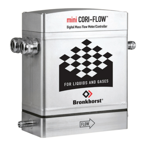
mini CORI-FLOW™ MI-series MKII
Industrial Coriolis Mass Flow
Meters/Controllers for Liquids and Gases
Doc. no.: 9.17.206 rev. A
Date: 19-03-2024
ATTENTION
Please read this document carefully before installing and operating the product.
Not following the guidelines could result in personal injury and/or damage to the equipment.
Keep this document for future reference.
Advertisement
Table of Contents


Need help?
Do you have a question about the miniCORI-FLOW MI MKII Series and is the answer not in the manual?
Questions and answers