Table of Contents
Advertisement
Advertisement
Table of Contents

Related Manuals for Cisco Nexus 93360YC-FX2


Summary of Contents for Cisco Nexus 93360YC-FX2
- Page 1 Cisco Nexus 93360YC-FX2 NX-OS Mode Switch Hardware Installation Guide First Published: 2019-07-20 Last Modified: 2020-07-22 Americas Headquarters Cisco Systems, Inc. 170 West Tasman Drive San Jose, CA 95134-1706 http://www.cisco.com Tel: 408 526-4000 800 553-NETS (6387) Fax: 408 527-0883...
- Page 2 Cisco and the Cisco logo are trademarks or registered trademarks of Cisco and/or its affiliates in the U.S. and other countries. To view a list of Cisco trademarks, go to this URL: https://www.cisco.com/c/en/us/about/legal/trademarks.html. Third-party trademarks mentioned are the property of their respective owners. The use of the word partner does not imply a partnership relationship between Cisco and any other company.
-
Page 3: Table Of Contents
Rack and Cabinet Requirements Clearance Requirements C H A P T E R 3 Installing the Chassis Installation Options with Rack-Mount Kits Install a Rack Unpacking and Inspecting a New Switch Cisco Nexus 93360YC-FX2 NX-OS Mode Switch Hardware Installation Guide... - Page 4 Removing an HVAC/HVDC Power Supply Removing a DC Power Supply Installing an AC Power Supply Installing an HVAC/HVDC Power Supply Installing a DC Power Supply Wiring a 48 V DC Electrical Connector Block Cisco Nexus 93360YC-FX2 NX-OS Mode Switch Hardware Installation Guide...
- Page 5 LEDs Switch Chassis LEDs Fan Module LEDs Power Supply LEDs A P P E N D I X D Additional Kits Rack Mount Kit NXK-ACC-RMK-2RU Rack Mount Kit N9K-C9300-RMK Vent Bracket Cisco Nexus 93360YC-FX2 NX-OS Mode Switch Hardware Installation Guide...
- Page 6 Contents Cisco Nexus 93360YC-FX2 NX-OS Mode Switch Hardware Installation Guide...
-
Page 7: Preface
Braces and a vertical bar within square brackets indicate a required choice within an optional element. Indicates a variable for which you supply values, in context where italics variable cannot be used. Cisco Nexus 93360YC-FX2 NX-OS Mode Switch Hardware Installation Guide... -
Page 8: Documentation Feedback
What's New in Cisco Product Documentation, at: https://www.cisco.com/warp/public/687/Directory/DirTAC.shtml. Subscribe to What's New in Cisco Product Documentation, which lists all new and revised Cisco technical documentation as an RSS feed and delivers content directly to your desktop using a reader application. The RSS feeds are a free service. -
Page 9: Overview
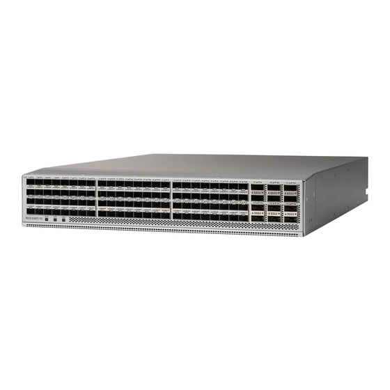
• Overview, on page 1 Overview The Cisco Nexus 93360YC-FX2 switch (N9K-C93360YC-FX2) is a 2-rack unit (RU), fixed-port switch designed for deployment in data centers. This switch has the following ports: • 96 10-/25-Gigabit SFP28 ports • 12 40/100-Gigabit QSFP28 ports •... - Page 10 Deployment Scheme for SFP-10G-T-X Transceivers The following figure shows the maximum configuration density of SFP-10G-T-X SFP+ transceivers for this switch. The following figure shows the switch features on the port side of the chassis. Cisco Nexus 93360YC-FX2 NX-OS Mode Switch Hardware Installation Guide...
- Page 11 Power supply modules (1 or 2) (AC power supplies shown) with slots numbered 1 (top) and 2 (bottom) Management port (1—RJ-45 copper port) The following figure shows the side of the chassis. Cisco Nexus 93360YC-FX2 NX-OS Mode Switch Hardware Installation Guide...
- Page 12 If you have only one power supply installed, you can install the replacement power supply in the open slot before removing the original power supply. Cisco Nexus 93360YC-FX2 NX-OS Mode Switch Hardware Installation Guide...
- Page 13 If the switch has port-side exhaust airflow (blue coloring for fan modules), you must locate the ports in the hot aisle. If you locate the air intake in a hot aisle, the switch can overheat and shut down. Cisco Nexus 93360YC-FX2 NX-OS Mode Switch Hardware Installation Guide...
- Page 14 Overview Overview Cisco Nexus 93360YC-FX2 NX-OS Mode Switch Hardware Installation Guide...
-
Page 15: Preparing The Site
Altitude Requirements Altitude rating is based on power supply installed; see critical components list in the system CB report for altitude rating. Cisco Nexus 93360YC-FX2 NX-OS Mode Switch Hardware Installation Guide... -
Page 16: Dust And Particulate Requirements
The wiring is unlikely to emit radio interference if you use a twisted-pair cable with a good distribution of grounding conductors. If you exceed the recommended distances, use a high-quality twisted-pair cable with one ground conductor for each data signal when applicable. Cisco Nexus 93360YC-FX2 NX-OS Mode Switch Hardware Installation Guide... -
Page 17: Shock And Vibration Requirements
Planning for Power Requirements The switch includes two power supplies (1-to-1 redundancy with current sharing) in one of the following combinations: • Two 1200-W AC power supplies • Two 1200-W HVAC/HVDC power supplies Cisco Nexus 93360YC-FX2 NX-OS Mode Switch Hardware Installation Guide... - Page 18 • Ensure that the protective devices are rated not greater than 30A when the switch is powered with regular DC power supplies (rated 48-60VDC). • Ensure that the protective devices are rated not greater than 10A when the switch is powered with HVDC power supplies (rated 240-350VDC). Cisco Nexus 93360YC-FX2 NX-OS Mode Switch Hardware Installation Guide...
-
Page 19: Airflow Requirements
• Standard open four-post Telco racks Work with your cabinet vendors to determine which of their cabinets meet the following requirements or see the Cisco Technical Assistance Center (TAC) for recommendations: Cisco Nexus 93360YC-FX2 NX-OS Mode Switch Hardware Installation Guide... -
Page 20: Clearance Requirements
For the clearances required for an installation of this chassis in a four-post rack, see the following figure. Chassis Depth of the chassis Vertical rack-mount posts and rails Maximum extension of the bottom-support rails Cisco Nexus 93360YC-FX2 NX-OS Mode Switch Hardware Installation Guide... - Page 21 Width of the front clearance area (equal to the width of the chassis with two rack-mount brackets that are attached to it). Note Both the front and rear of the chassis must be open to both aisles for airflow. Cisco Nexus 93360YC-FX2 NX-OS Mode Switch Hardware Installation Guide...
- Page 22 Preparing the Site Clearance Requirements Cisco Nexus 93360YC-FX2 NX-OS Mode Switch Hardware Installation Guide...
-
Page 23: Installing The Chassis
You can install the switch using the following rack-mount options: • Rack-mount kit (NXK-ACC-RMK-2RU) which you can order from Cisco. This option offers you easy installation, greater stability, increased weight capacity, added accessibility, and improved removability with front and rear removal. -
Page 24: Install A Rack
If you need to move or ship the system in the future, you will need this container. Step 1 Compare the shipment to the equipment list that is provided by your customer service representative and verify that you have received all of the ordered items. Cisco Nexus 93360YC-FX2 NX-OS Mode Switch Hardware Installation Guide... -
Page 25: Planning How To Position The Chassis In The Rack
All fan and power supply modules in the same switch must operate with the same direction of airflow and the air intake portion of the switch must be located in a cold aisle. Cisco Nexus 93360YC-FX2 NX-OS Mode Switch Hardware Installation Guide... -
Page 26: Installing The Chassis In A Two-Post Rack
Be sure to align four of the screw holes on the larger side of the bracket with the four screw holes near the center of the left or right side of the chassis. Cisco Nexus 93360YC-FX2 NX-OS Mode Switch Hardware Installation Guide... -
Page 27: Installing The Chassis In A Two-Post Rack
To prevent personal injury or damage to the chassis, never attempt to lift or tilt the chassis using the handles on modules (such as power supplies, fans, or cards); these types of handles are not designed to support the weight of the unit. Cisco Nexus 93360YC-FX2 NX-OS Mode Switch Hardware Installation Guide... - Page 28 If these modules have a blue coloring for port-side exhaust airflow, then you must position the modules by the cold aisle. If the modules have a burgundy coloring for port-side intake airflow, you must position the modules by the hot aisle. Cisco Nexus 93360YC-FX2 NX-OS Mode Switch Hardware Installation Guide...
-
Page 29: Installing The Chassis In A Four-Post Rack
Determine which end of the chassis is to be located in the cold aisle as follows: • If the switch has port-side intake modules (fan modules with burgundy coloring), position the front-mount brackets so that the switch ports will be in the cold aisle. Cisco Nexus 93360YC-FX2 NX-OS Mode Switch Hardware Installation Guide... - Page 30 12-24 screws or 10-32 screws, depending on the rack thread type (see the following figure). Tighten 12-24 screws to 30 in-lb (3.39 N·m) of torque and tighten 10-32 screws to 20 in-lb (2.26 N·m) of torque. Cisco Nexus 93360YC-FX2 NX-OS Mode Switch Hardware Installation Guide...
- Page 31 Align the retainer brackets to the front of the chassis, being careful not to damage anything on the front of the chassis (see the following figure). b) Repeat Step 5 to attach the other retainer bracket on other side of the chassis. Cisco Nexus 93360YC-FX2 NX-OS Mode Switch Hardware Installation Guide...
- Page 32 (see the following figure). b) Attach the screws to secure the retainer clip (see the following figure). c) Repeat Step 6 to attach the other retainer clip on the other side of the chassis. Cisco Nexus 93360YC-FX2 NX-OS Mode Switch Hardware Installation Guide...
-
Page 33: Installing The Switch Using The N9K-C9300-Rmk Rack-Mount Kit
• Port-side exhaust (blue coloring for fan modules) airflow requires that the bottom-support rail with the chassis stop be located on the cold aisle side of the rack. Cisco Nexus 93360YC-FX2 NX-OS Mode Switch Hardware Installation Guide... - Page 34 Tighten each screw to the appropriate torque setting for the screws (for M6 x 10 mm screws, use 40 in. lbs [4.5 N·m] of torque). Cisco Nexus 93360YC-FX2 NX-OS Mode Switch Hardware Installation Guide...
- Page 35 What to do next You are ready to install two front-mount brackets on the chassis. Cisco Nexus 93360YC-FX2 NX-OS Mode Switch Hardware Installation Guide...
-
Page 36: Attaching Front-Mount Brackets To The Chassis
You need to slide the chassis onto the bottom-support rails so that the power supply end locks onto the chassis stops at the end of the rails and so that the front-mount brackets on the chassis come into contact with the front-mount rails on the rack. Cisco Nexus 93360YC-FX2 NX-OS Mode Switch Hardware Installation Guide... - Page 37 Be sure that the sides of the chassis by the power supplies clips into the chassis stops on the bottom-support rails and the front-mount brackets come in contact with the rack (see the following figure). Cisco Nexus 93360YC-FX2 NX-OS Mode Switch Hardware Installation Guide...
- Page 38 (for M6 x 10 mm screws, use 40 in-lbs [4.5 N·m] of torque). Cisco Nexus 93360YC-FX2 NX-OS Mode Switch Hardware Installation Guide...
-
Page 39: Installing The Airflow Vent Nxa-Acc-Bav4
Holding the vent bracket level, insert screws (12-24 or 10-32, depending on the rack type) in each of the front rack-mount flanges (using a total of two screws) and into the cage nuts or threaded holes in the vertical rack-mounting rails (see item 2 in the following figure). Cisco Nexus 93360YC-FX2 NX-OS Mode Switch Hardware Installation Guide... -
Page 40: Grounding The Chassis
Step 1 Use a wire-stripping tool to remove approximately 0.75 inch (19 mm) of the covering from the end of the grounding wire. We recommend 6-AWG wire for the U.S. installations. Cisco Nexus 93360YC-FX2 NX-OS Mode Switch Hardware Installation Guide... -
Page 41: Starting The Switch
• The rack must be close enough to the dedicated power source so that you can connect the switch to the power source by using a designated power cables. • You have the designated power cables for the power supplies that you are connecting to the dedicated power sources. Cisco Nexus 93360YC-FX2 NX-OS Mode Switch Hardware Installation Guide... - Page 42 If there is a safety cover for the terminals, place and secure it over the terminals to avoid an electrical shock hazard. e) Turn on the power at the circuit breaker for the DC power source. Step 4 Verify that the power supply LED is on and green. Cisco Nexus 93360YC-FX2 NX-OS Mode Switch Hardware Installation Guide...
- Page 43 A setup utility automatically launches the first time that you access the switch and guides you through the basic configuration. For instructions on how to configure the switch and check module connectivity, see the appropriate Cisco Nexus 9000 Series configuration guide.
- Page 44 Installing the Chassis Starting the Switch Cisco Nexus 93360YC-FX2 NX-OS Mode Switch Hardware Installation Guide...
-
Page 45: Connecting The Switch To The Network
When running cables in overhead or subfloor cable trays, we strongly recommend that you locate power cables and other potential noise sources as far away as practical from network cabling that terminates on Cisco equipment. In situations where long parallel cable runs cannot be separated by at least 3.3 feet (1 meter), we recommend that you shield any potential noise sources by housing them in a grounded metallic conduit. - Page 46 Connect the other end of the RJ-45 rollover cable to the console or to a modem. What to do next You are ready to create the initial switch configuration (see Creating the Initial Switch Configuration, on page 39). Cisco Nexus 93360YC-FX2 NX-OS Mode Switch Hardware Installation Guide...
-
Page 47: Creating The Initial Switch Configuration
To connect the switch to the network, you can use the default choices for each configuration except the IP address, which you must provide. You can perform the other configurations later as described in the Cisco Nexus 9000 Series NX-OS Fundamentals Configuration Guide. -
Page 48: Setting Up The Management Interface
RJ-45 connectors. For longer connections, you can use an optical cable with SFP transceivers (LH or SX type). Note Use only one of these management ports—the switch does not support the use of both management ports. Cisco Nexus 93360YC-FX2 NX-OS Mode Switch Hardware Installation Guide... -
Page 49: Connecting Interface Ports To Other Devices
Invisible laser radiation may be emitted from disconnected fibers or connectors. Do not stare into beams or view directly with optical instruments. Downlink Connections For a listing of the transceivers and cables that the optical downlink ports support, see http://www.cisco.com/c/en/us/support/interfaces-modules/transceiver-modules/products-device-support-tables-list.html Cisco Nexus 93360YC-FX2 NX-OS Mode Switch Hardware Installation Guide... - Page 50 Connecting the Switch to the Network Downlink Connections Cisco Nexus 93360YC-FX2 NX-OS Mode Switch Hardware Installation Guide...
-
Page 51: Replacing Components
Hold the module by its handle and do not touch the electrical connectors on its backside. Also, to protect the electrical connectors, avoid letting them come in contact with anything other than the electrical connectors inside the chassis. Cisco Nexus 93360YC-FX2 NX-OS Mode Switch Hardware Installation Guide... -
Page 52: Replacing A Power Supply Module
If the STS LED does not turn on, slide the module out of the chassis, and visually check the electrical connectors on the back side of the chassis for damage. If damaged, contact Cisco Technical Assistance for help. If undamaged, repeat the previous step to reinstall the module. -
Page 53: Removing An Hvac/Hvdc Power Supply
Turn off the circuit breaker for the power feed to the power supply that you are replacing. Be sure that the LEDs turn off on the power supply that you are removing. Cisco Nexus 93360YC-FX2 NX-OS Mode Switch Hardware Installation Guide... -
Page 54: Installing An Ac Power Supply
If the power supply does not fit into the open slot, turn the module over before sliding it carefully into the open Note slot. Step 2 Test the installation by trying to pull the power supply out of the slot without using the release latch. Cisco Nexus 93360YC-FX2 NX-OS Mode Switch Hardware Installation Guide... -
Page 55: Installing An Hvac/Hvdc Power Supply
Step 3 If the DC power cables and a grounding cable are already connected to an electrical connector block, insert the block into the power receptacle on the power supply. Cisco Nexus 93360YC-FX2 NX-OS Mode Switch Hardware Installation Guide... -
Page 56: Installing A Dc Power Supply
If the electrical cables have not been connected to the electrical connector block, wire them as described in Wiring a 48 V DC Electrical Connector Block, on page Step 3 Turn on the circuit breaker for the DC power source connected to the power supply. Cisco Nexus 93360YC-FX2 NX-OS Mode Switch Hardware Installation Guide... -
Page 57: Wiring A 48 V Dc Electrical Connector Block
Strip 0.6 inches (15 mm) of insulation off the DC wires that you are using. Step 4 Orient the connector as shown in the following figure with the orange plastic button on top. Cisco Nexus 93360YC-FX2 NX-OS Mode Switch Hardware Installation Guide... - Page 58 "+ DC". Step 9 Verify that the other ends of the cables are attached to the DC power source and ground. You are then ready to turn on the DC power source. Cisco Nexus 93360YC-FX2 NX-OS Mode Switch Hardware Installation Guide...
-
Page 59: Rack Specifications
• Standard 19-inch (48.3 cm) (two- or four-post EIA cabinet or rack, with mounting rails that conform to English universal hole spacing per section 1 of ANSI/EIA-310-D-1992). For more information, see Requirements Specific to Perforated Cabinets, on page Cisco Nexus 93360YC-FX2 NX-OS Mode Switch Hardware Installation Guide... -
Page 60: Requirements Specific To Standard Open Racks
To help with cable management, you might want to allow additional space in the rack above and below the chassis to make it easier to route all of the fiber optic or copper cables through the rack. Cisco Nexus 93360YC-FX2 NX-OS Mode Switch Hardware Installation Guide... -
Page 61: Appendix B System Specifications
Ambient operating temperature 32 to 104°F (0 to 40°C) Ambient nonoperating –40 to 158°F (–40 to 70°C) Relative Nonoperating 5 to 95% humidity Altitude Operating 0 to 13,123 feet (0 to 4,000 meters) Cisco Nexus 93360YC-FX2 NX-OS Mode Switch Hardware Installation Guide... -
Page 62: Switch Dimensions
(burgundy) (NXA-PDC-930W-PI) Transceiver and Cable Specifications To determine which transceivers, adapters, and cables are supported by this switch, see https://www.cisco.com/ c/en/us/support/interfaces-modules/transceiver-modules/products-device-support-tables-list.html. To see the transceiver specifications and installation information, see https://www.cisco.com/c/en/us/support/ interfaces-modules/transceiver-modules/products-device-support-tables-list.html. Cisco Nexus 93360YC-FX2 NX-OS Mode Switch Hardware Installation Guide... -
Page 63: Switch Power Input Requirements
Maximum hold-up time 12 ms at 650 W Power supply output voltage 12 VDC Power supply standby voltage 12 VDC Efficiency rating Climate Savers Platinum Efficiency (80Plus Platinum certified) Form factor RSP1 Cisco Nexus 93360YC-FX2 NX-OS Mode Switch Hardware Installation Guide... -
Page 64: 1200-W Hvac/Hvdc Power Supply Specifications
-60 VDC Maximum DC input current 23 A at -48 VDC Maximum input W 1104 W Maximum output power per power supply 930 W Maximum inrush current 35 A (sub-cycle duration) Cisco Nexus 93360YC-FX2 NX-OS Mode Switch Hardware Installation Guide... -
Page 65: Power Cable Specifications
250 VAC, 10 A, CEI 23-16/VII plug, 8.2 feet (2.5 m) Japan CAB-C13-C14-2M-JP Power Cord Jumper, C13-C14 Connectors, 6.6 feet (2.0 m) North America CAB-9K12A-NA 125 VAC, 13 A, NEMA 5-15 plug, 8.2 feet (2.5 m) Cisco Nexus 93360YC-FX2 NX-OS Mode Switch Hardware Installation Guide... -
Page 66: Hvac/Hvdc Power Cables Supported By Aci-Mode And Nx-Os Mode Switches
2-foot (0.6 m) cable with Saf-D-Grid and RT connector 277V AC CAB-HVDC-3T-2M HVDC 6.6-foot (2.0 m) cable with Saf-D-Grid and three terminal connectors 300V AC / 400V DC (+200/-200 V DC) Cisco Nexus 93360YC-FX2 NX-OS Mode Switch Hardware Installation Guide... -
Page 67: Dc Power Cable Specifications
Products should comply with CE Markings according to directives 2004/108/EC and 2006/95/EC. Safety • CAN/CSA-C22.2 No. 60950-1 Second Edition • EN 60950-1 Second Edition • IEC 60950-1 Second Edition • AS/NZS 60950-1 • GB4943 Cisco Nexus 93360YC-FX2 NX-OS Mode Switch Hardware Installation Guide... - Page 68 • CNS13438 Class A EMC: Immunity • EN55024 • CISPR24 • EN300386 • KN 61000-4 series RoHS The product is RoH-6 compliant with exceptions for leaded-ball grid-array (BGA) balls and lead press-fit connectors. Cisco Nexus 93360YC-FX2 NX-OS Mode Switch Hardware Installation Guide...
-
Page 69: Leds
Temperature exceeds the major alarm threshold. The switch is not receiving power. Green Fans and power supply modules are operational. Amber At least one fan or power supply module is not operating. Cisco Nexus 93360YC-FX2 NX-OS Mode Switch Hardware Installation Guide... -
Page 70: Fan Module Leds
Power supply is not receiving power. Green Flashing amber Power supply warning—possibly one of the following conditions: • High voltage • High power • Low voltage • Slow power supply fan Cisco Nexus 93360YC-FX2 NX-OS Mode Switch Hardware Installation Guide... -
Page 71: Additional Kits
• M4 x 8-mm Phillips pan-head screws (2) Not applicable EAC Compliance document Not applicable Hazardous substances list for customers in China The following table lists and illustrates the console cable (CAB-CONSOLE-RJ45) that can be ordered. Cisco Nexus 93360YC-FX2 NX-OS Mode Switch Hardware Installation Guide... -
Page 72: Rack Mount Kit N9K-C9300-Rmk
Vent Bracket The following table lists and illustrates the vent bracket (NXA-ACC-BAV4). Note You require the vent bracket (NXA-ACC-BAV4) for NEBS (Network Equipment-Building System) compliance only. Illustration Description Quantity Vent bracket Cisco Nexus 93360YC-FX2 NX-OS Mode Switch Hardware Installation Guide...
Need help?
Do you have a question about the Nexus 93360YC-FX2 and is the answer not in the manual?
Questions and answers