Table of Contents
Advertisement
Quick Links
Face Recognition Terminal
Quick Start Guide
UD19294B-A
© 2020 Hangzhou Hikvision Digital Technology Co., Ltd. All rights reserved.
This Manual is the property of Hangzhou Hikvision Digital Technology Co., Ltd. or its affiliates
(hereinafter referred to as "Hikvision"), and it cannot be reproduced, changed, translated, or
distributed, partially or wholly, by any means, without the prior written permission of Hikvision.
Unless otherwise expressly stated herein, Hikvision does not make any warranties, guarantees or
representations, express or implied, regarding to the Manual, any information contained herein.
About this Manual
The Manual includes instructions for using and managing the Product. Pictures, charts, images and
all other information hereinafter are for description and explanation only. The information contained
in the Manual is subject to change, without notice, due to firmware updates or other reasons. Please
find the latest version of this Manual at the Hikvision website (https://www.hikvision.com/).
Please use this Manual with the guidance and assistance of professionals trained in supporting the
Product.
Trademarks Acknowledgement
and other Hikvision's trademarks and logos are the properties of Hikvision in various
jurisdictions.
Other trademarks and logos mentioned are the properties of their respective owners.
LEGAL DISCLAIMER
TO THE MAXIMUM EXTENT PERMITTED BY APPLICABLE LAW, THIS MANUAL AND THE PRODUCT
DESCRIBED, WITH ITS HARDWARE, SOFTWARE AND FIRMWARE, ARE PROVIDED "AS IS" AND "WITH
ALL FAULTS AND ERRORS". HIKVISION MAKES NO WARRANTIES, EXPRESS OR IMPLIED, INCLUDING
WITHOUT LIMITATION, MERCHANTABILITY, SATISFACTORY QUALITY, OR FITNESS FOR A PARTICULAR
PURPOSE. THE USE OF THE PRODUCT BY YOU IS AT YOUR OWN RISK. IN NO EVENT WILL HIKVISION
BE LIABLE TO YOU FOR ANY SPECIAL, CONSEQUENTIAL, INCIDENTAL, OR INDIRECT DAMAGES,
INCLUDING, AMONG OTHERS, DAMAGES FOR LOSS OF BUSINESS PROFITS, BUSINESS INTERRUPTION,
OR LOSS OF DATA, CORRUPTION OF SYSTEMS, OR LOSS OF DOCUMENTATION, WHETHER BASED ON
BREACH OF CONTRACT, TORT (INCLUDING NEGLIGENCE), PRODUCT LIABILITY, OR OTHERWISE, IN
CONNECTION WITH THE USE OF THE PRODUCT, EVEN IF HIKVISION HAS BEEN ADVISED OF THE
POSSIBILITY OF SUCH DAMAGES OR LOSS.
YOU ACKNOWLEDGE THAT THE NATURE OF INTERNET PROVIDES FOR INHERENT SECURITY RISKS,
AND HIKVISION SHALL NOT TAKE ANY RESPONSIBILITIES FOR ABNORMAL OPERATION, PRIVACY
LEAKAGE OR OTHER DAMAGES RESULTING FROM CYBER-ATTACK, HACKER ATTACK, VIRUS
INSPECTION, OR OTHER INTERNET SECURITY RISKS; HOWEVER, HIKVISION WILL PROVIDE TIMELY
TECHNICAL SUPPORT IF REQUIRED.
YOU AGREE TO USE THIS PRODUCT IN COMPLIANCE WITH ALL APPLICABLE LAWS, AND YOU ARE
SOLELY RESPONSIBLE FOR ENSURING THAT YOUR USE CONFORMS TO THE APPLICABLE LAW.
ESPECIALLY, YOU ARE RESPONSIBLE, FOR USING THIS PRODUCT IN A MANNER THAT DOES NOT
INFRINGE ON THE RIGHTS OF THIRD PARTIES, INCLUDING WITHOUT LIMITATION, RIGHTS OF
PUBLICITY, INTELLECTUAL PROPERTY RIGHTS, OR DATA PROTECTION AND OTHER PRIVACY RIGHTS.
YOU SHALL NOT USE THIS PRODUCT FOR ANY PROHIBITED END-USES, INCLUDING THE DEVELOP-
MENT OR PRODUCTION OF WEAPONS OF MASS DESTRUCTION, THE DEVELOPMENT OR
PRODUCTION OF CHEMICAL OR BIOLOGICAL WEAPONS, ANY ACTIVITIES IN THE CONTEXT RELATED
TO ANY NUCLEAR EXPLOSIVE OR UNSAFE NUCLEAR FUEL-CYCLE, OR IN SUPPORT OF HUMAN RIGHTS
ABUSES.
IN THE EVENT OF ANY CONFLICTS BETWEEN THIS MANUAL AND THE APPLICABLE LAW, THE LATER
PREVAILS.
Data Protection
During the use of device, personal data will be collected, stored and processed. To protect data, the
development of Hikvision devices incorporates privacy by design principles. For example, for device
with facial recognition features, biometrics data is stored in your device with encryption method; for
fingerprint device, only fingerprint template will be saved, which is impossible to reconstruct a
fingerprint image.
As data controller, you are advised to collect, store, process and transfer data in accordance with the
applicable data protection laws and regulations, including without limitation, conducting security
controls to safeguard personal data, such as, implementing reasonable administrative and physical
security controls, conduct periodic reviews and assessments of the effectiveness of your security
controls.
Scan the QR code to get the user manual for detailed information.
Note that mobile data charges may apply if Wi-Fi is unavailable.
Use only power supplies listed in the user instructions:
Model
Manufacturer
Standard
C2000IC12.0-24P-DE
MOSO Power Supply Technology Co., Ltd. CEE
C2000IC12.0-24P-GB
MOSO Power Supply Technology Co., Ltd. BS
KPL-040F-VI
Channel Well Technology Co., Ltd.
CEE
1
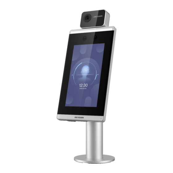
Appearance
126.6 mm
70.0 mm
Thermographic Module
White Light
IR Light
IR Light
Camera
Touch Screen
USB
Interface
122.1 mm
The figures here are for reference only.
3.1
Device Wiring (Normal)
2
Installation
Installation Environment:
Moutning with Bracket
Avoid backlight, direct sunlight, and indirect sunlight.
Before you start:
For better recognition, there should be light source in or near
the installation environment.
1. Use 4 screws (M3 or M4), secured by flange
nuts, to install the reinforcing board on the inner
surface of the turnstile.
The distance between the turnstile and the edge
should be no longer than 10 mm.
2. Drill holes on the turnstile's inner surface
according to the figure displayed below. And
install water-proof nut.
Direct Sunlight
Backlight
Direct Sunlight
through Window
Solder after pressing rivets to avoid water from
entering.
Width of Reinforcing Board>125 mm
15 mm (Suggested)
Indirect Sunlight
Close to Light
through Window
Temperature Measurement Environment:
Sunlight, wind, hot/cool air from air conditioner and other external
factors, which may affect surface temperature, will create the deviation
of the temperature measurement. In order to get an accurate result,
make sure the device is applied indoors and windlessly (where is
relatively isolated from the outdoors). The working temperature should
keep between 10 °C and 35 °C. If there are no suitable environments for
temperature measurement (the area faces the indoor and connects the
outdoor, the area at the door of the indoor environment, etc.), building
a temporary temperature measurement environment is suggested.
Influence Factors of Temperature Measurement:
Wind: The wind will take the heat away, which may affect the
measurement result.
Sweat: The sweat will take the heat away, which may affect the
measurement result.
Air Conditioner (Cool Air): If the indoor temperature is low, the surface
Inner Surface
temperature may also lower than the actual temperature, which may
of Turnsitle
affect the measurement result.
Air Conditioner (Heat) or Heating: If the indoor temperature is high, the
surface temperature may also higher than the actual temperature,
which may affect the measurement result.
In order to make the device work properly, you should wait for 90 min
after the device is powered on.
BTN
Network Interface
1
Lower Cover
Screw
2
Base
Upper Cover
Use 4 screws (M3 or M4),
Secured by flange nuts
Press 8 rivet water-proof
45°
nut
Model: BS-M6-1
Steps:
Rotate to open the lower cover.
1
Route the cables through the cable hole on the turnstile.
67 mm
4- 12 mm Soldering Hole
2
Solder the four holes,
Align the holes on the base with those on the turnstile and
polish the outer surface,
place the device with bracket on the tunstile.
and implement with wire
Use 4 screws to secure the bracket and the turnstile.
drawing.
Reinforcing Board
Cover the lower cover on the base and rotate to secure.
3
Loosen the screws inside and adjust the device elevation.
4
After adjustment, secure the screws and install the upper
cover.
The default elevation angle is 15°. The adjustable elevation
angle is from 0° to 15°.
When connecting door magnetic sensor and exit button,
the device and the RS-485 card reader should use the common
ground connection.
The Wiegand terminal here is a Wiegand input terminal. You
should set the face recognition terminal's Wiegand direction to
"Input". If you should connect to an access controller, you should
set the Wiegand direction to "Output". For details, see the user
manual.
The suggested external power supply for door lock is 12 V, 1 A.
The suggested external power supply for Wiegand card reader
is 12 V, 1A.
Do not wire the device to the electric supply directly.
(NC)
(COM)
(NO)
Door Contact
3
Turnstile
4
Screws for
Elevation
Adjustment
Advertisement
Table of Contents

Subscribe to Our Youtube Channel
Related Manuals for HIKVISION DS-K5671-3XF/ZU


Summary of Contents for HIKVISION DS-K5671-3XF/ZU
- Page 1 WITHOUT LIMITATION, MERCHANTABILITY, SATISFACTORY QUALITY, OR FITNESS FOR A PARTICULAR PURPOSE. THE USE OF THE PRODUCT BY YOU IS AT YOUR OWN RISK. IN NO EVENT WILL HIKVISION BE LIABLE TO YOU FOR ANY SPECIAL, CONSEQUENTIAL, INCIDENTAL, OR INDIRECT DAMAGES,...
- Page 2 Regulatory Information Device Wiring (With Secure Door Control Unit) Temperature Measurement Settings Face Recognition Terminal Secure Door Control Unit FCC Information Please take attention that changes or modification not expressly approved by the party responsible for compliance could void the user’s authority to operate the equipment. FCC compliance: This equipment has been tested and found to comply with the 1 Hold the screen surface and verify the identity to enter the main page.
Need help?
Do you have a question about the DS-K5671-3XF/ZU and is the answer not in the manual?
Questions and answers