
Related Manuals for quiko SCARABEO QK-SCA24


Summary of Contents for quiko SCARABEO QK-SCA24
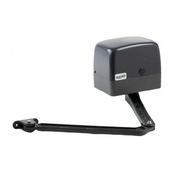
- Page 1 SCARABEO NEW 2016 MODEL ARTICULATED ARM GEARMOTOR FOR SWING GATES V03/2016...
- Page 2 ATTENTION For a proper functioning of the system, ground stops must be installed for both opening and closing Closing ground stop Opening ground stop...
-
Page 3: Packing Contents
................PACKING CONTENTS ................... TECHNICAL DATA ..... VIEW OF TYPICAL AUTOMATION AND NAMES OF COMPONENTS ..................DIMENSIONS .......... TYPICAL CONNECTION AND CABLE SECTION ........... CONSIDERATIONS FOR INSTALLATION ..................4-5-6 INSTALLATION ................TROUBLESHOOTING PACKING CONTENTS 1- Operator 1- Fastening plates 1- Unlocking key 1- Capacitor (230Vca) TECHNICAL DATA... - Page 4 VIEW OF TYPICAL AUTOMATION AND NAMES OF COMPONENTS 1- Operator 5- Internal photocell 2- External photocell 6- Electronic control unit 3- Flashing warning light 7- Key-switch 4- Antenna 8- Remote control DIMENSIONS...
-
Page 5: Considerations For Installation
TYPICAL CONNECTION AND CABLE SECTION 2X1,5mm2 (24 Vdc ) 4X1,5mm2 (230 Vca ) 2X0,75mm2 RX Photocell TX Photocell 4X0,75mm2 2X0,75mm2 4X0,75mm2 3X1,5mm2 230V Line CONSIDERATIONS FOR INSTALLATION · The installation and testing operations must be performed solely by qualified personnel in order to guarantee the proper and safe operation of the automatic gate. ·... - Page 6 B Max 120° To find the desired angle, release the motor and couple the lever Move the wing to the stop and mark the fastening point of the lever coupling plate to the gate Opening example at 90° indoor (indicative measures) 50 cm 15 cm...
- Page 7 Opening example over 90° indoor (indicative measures) 50 cm 20 cm 20 cm Opening example at 90° outdoor (indicative measures) 35 cm 15 cm EMERGENCY RELEASE Ÿ Insert the key provided into the appropriate lock on the rear on the motor Ÿ...
-
Page 8: Troubleshooting
TROUBLESHOOTING SOLUTION PROBLEM PROBABLE CAUSE 230 volt mains voltage Check master switch absent Check for any STOP selectors or commands. Emergency STOP present If not used, check jumper On giving a command with on STOP contact input on the remote the control board control or with the key-switch, the gate... -
Page 9: Maintenance
GENERAL ADVICE Install a gate’s safety system that complies with current regulations. Choose short routes for cables and keep power cables separate from control ones. Install the control card in a waterproof box. Please refer to current regulations when setting the gear motor’s maximum torque. We advice you to install an outdoor switch, in compliance with European standards on the issue of safety, to turn the electricity off when servicing the gate. -
Page 10: Declaration Of Conformity
DECLARATION OF CONFORMITY (OF THE MANUFACTURER) Manufacturer: QUIKO ITALY SAS Via Seccalegno, 19 36040 Sossano (VI) Italia hereby declares, under his liability, that the products: QK-SCA24 , QK-SCA230 are in compliance with the essential safety requirements of the regulations: Electromagnetic Compatibility Directive ......2004/108/EC Low Voltage Directive ............2006/95/EC... - Page 11 DECLARATION OF CONFORMITY (OF THE INSTALLER) The undersigned: in charge of the set-up, declares that the product: Gate type: are in compliance with the essential safety requirements of the regulations: Electro magnetic Compatibility Directive ......2004/108/EC Low Voltage Directive ............2006/95/EC Machinery Directive ..............2006/42/EC and also declares that the related and/or specific national technical regulations have been followed: EN 12453/EN 12445 on Industrial, Commercial and Residential Gates and Doors –...
- Page 12 Quiko Italy Via Seccalegno, 19 36040 Sossano (VI) - Italy Tel. +39 0444 785513 Fax +39 0444 782371 info@quiko.biz www.quikoitaly.com...
- Page 13 SCARABEO NUOVA VERSIONE 2016 AUTOMAZIONE A BRACCIO ARTICOLATO PER CANCELLI A BATTENTE V03/2016...
- Page 14 ATTENZIONE Per un corretto funzionamento del sistema, assicurarsi che le battute di apertura e chiusura siano installate Battuta di chiusura Battuta di apertura...
-
Page 15: Contenuto Dell'imballo
Composizione dell’imballo ..............Dati tecnici..................... Prospetto generale ................Dimensioni ..................Collegamento tipo e sezione cavi ............Considerazione per l’installazione ............Modalità’ di installazione ..............4-5-6 Inconvenienti : cause e soluzioni............CONTENUTO DELL’IMBALLO 1- Motoriduttore completo di bracci 1- Piastra di fissaggio completa di accessori 1- Chiave sblocco 1- Condensatore (230Vca) DATI TECNICI... - Page 16 1- Motoriduttori 5- Fotocellula interna 2- Fotocellula esterna 6- Quadro di comando 3- Lampeggiatore 7- Selettore a chiave 4- Antenna 8- Radiocomando DIMENSIONI...
-
Page 17: Collegamento Tipo E Sezione Cavi
COLLEGAMENTO TIPO E SEZIONE CAVI 2X1,5mm2 (12 Vdc ) 4X1,5mm2 (230 Vca ) 2X0,75mm2 RX Fotocellula TX Fotocellula 4X0,75mm2 2X0,75mm2 4X0,75mm2 3X1,5mm2 Linea 230V CONSIDERAZIONI PER L’INSTALLAZIONE · Le operazioni di installazione e collaudo devono essere eseguite solo da personale qualificato ai fini di garantire la corretta e sicura funzionalità del cancello automatico. - Page 18 B Max 120° Per trovare l’angolazione desiderata, sbloccare il motore e innestare la leva Portare l’anta fino a battuta e marcare il punto di fissaggio della piastra attacco leva al cancello Esempio di apertura a 90° all’interno (misure indicative) 50 cm 15 cm...
- Page 19 Esempio di apertura oltre i 90° all’interno (misure indicative) 50 cm 20 cm 20 cm Esempio di apertura a 90° all’esterno (misure indicative) 35 cm 15 cm PROCEDURA SBLOCCO EMERGENZA Ÿ Inserire la chiave in dotazione nell’apposita serratura posta sul retro del motore Ÿ...
-
Page 20: Inconvenienti-Cause E Soluzioni
INCONVENIENTI-CAUSE E SOLUZIONI INCONVENIENTE CAUSA PROBABILE SOLUZIONE Alimentazione di rete Controllare l’interrutore 230 volt assente principale Controllare eventuali selettori o comandi di Presenza di STOP di STOP. Se non utilizzati emergenza verificare ponticello su Ad un comando con ingresso contatto STOP il radiocomando o con su centralina il selettore a chiave,... -
Page 21: Manutenzione
RACCOMANDAZIONI DI CARATTERE GENERALE Integrare la sicurezza del cancello conformemente alla normativa vigente. Scegliere percorsi brevi per i cavi e tenere separati i cavi di potenza dai cavi di comando. Installare la scheda di comando in una scatola a tenuta stagna. Per la messa a punto della coppia massima del motoriduttore, attenersi alle normative in vigore. -
Page 22: Dichiarazione Di Conformita
DICHIARAZIONE DI CONFORMITA’ ( DEL PRODUTTORE) Costruttore: QUIKO ITALY SAS Via Seccalegno 19 36040 Sossano (VI) Italia dichiara sotto la propria responsabilità che i prodotti: QK- SCA24 , QK-SCA230 sono conformi ai requisiti essenziali di sicurezza delle direttive: Direttiva Macchine ........2006/42/CE;... - Page 23 DICHIARAZIONE DI CONFORMITA’ (da parte dell’installatore) Il sottoscritto: ________________________________________________________________________ Indirizzo: ________________________________________________________________________ in qualità di responsabile della messa in funzione dichiara che il prodotto: Tipologia _________________________________________________________________________ Ubicazione: ____________________________________________________________________ è conforme ai requisiti essenziali di sicurezza delle direttive: Direttiva Macchine ........2006/42/CE; Direttiva EMC...........
- Page 24 QUIKO ITALY Via Seccalegno, 19 36040 Sossano (VI) - Italy Tel. +39 0444 785513 Fax +39 0444 782371 info@quiko.biz www.quikoitaly.com...
Need help?
Do you have a question about the SCARABEO QK-SCA24 and is the answer not in the manual?
Questions and answers