
Subscribe to Our Youtube Channel
Related Manuals for quiko MOOVY QK-M300B


Summary of Contents for quiko MOOVY QK-M300B
- Page 1 MOOVY AUTOMATIONS FOR SLIDING GATES AUTOMAZIONI PER CANCELLI SCORREVOLI MOOVY AUTOMATIONS FOR SLIDING GATES USE AND MAINTENANCE MANUAL...
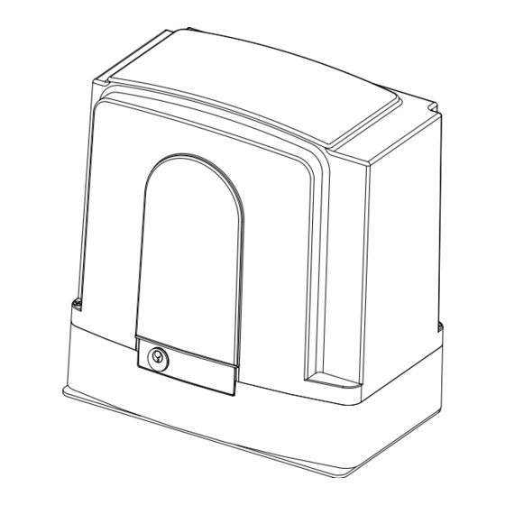
- Page 2 Dimensions: a=height; b=length; c=width 1- BEFORE INSTALLING THE AUTOMATION Before installing the automation, you must check that: The wheels of the gate are attached to make the gate stable and must be in good condition; The entire length of the fixed rail must be free of obstacles, straight and clean and have stoppers at the ends;...
-
Page 3: Materials For Installation
2- MATERIALS FOR INSTALLATION FIG. 1 1. Gearmotor 2. Counterplate 3. Limit switches brackets (cammes) 4. M4 rack 5. M10 Anchor bolts 3- POSITIONING THE COUNTERPLATE Dig a concrete foundation base following measurements shown on fig. 2, 3. Position the counterplate making sure it is perfectly levelled and smooth and complying with the measurements shown on fig. - Page 4 FIG. 3...
- Page 5 FIG. 4 6- POSITIONING THE LIMIT SWITCHES BRACKETS (CAMMES) FIG. 5 Manually position the gate completely open and fasten the limit switch brackets (1) (2) onto the rack so that the limit switch lever exceeds the length of the brackets by approximately two/thirds. Repeat the operation with gate completely closed.
- Page 6 7- UNLOCKING THE MOTOR MANUALLY FIG.6 RELEASE INSTRUCTION In case of fault or power failure, insert the key in the lever lock and turn it of 90°CW. Pull and turn the lever approx. 90°until it stops and the gate move manually. ! WARNING: perform locking and lock release operations with motor cut off.
-
Page 7: Typical Installation
9- TYPICAL INSTALLATION FIG. 9 CONNECTIONS CABLES Cables section sqmm POWER SUPPLY 3x1,5 TX PHOTOCELL ON POST 2x0,75 RX PHOTOCELL ON POST 4x0,75 TX PHOTOCELLS 2x0,75 RX PHOTOCELLS 4x0,75 KEY SELECTOR FLASHING LAMP AERIAL RG59 FOR THE ELECTRICAL CONNECTIONS REFER TO THE USER MANUAL OF THE CONTROL BOARD... -
Page 8: General Advice
GENERAL ADVICE Install a gate’s safety system that complies with current regulations. Choose short routes for cables and keep power cables separate from control ones. Install the control card in a waterproof box. Please refer to current regulations when setting the gear motor’s maximum torque. We advice you to install an outdoor switch, in compliance with European standards on the issue of safety, to turn the electricity off when servicing the gate. -
Page 9: Declaration Of Compliance
DECLARATION OF COMPLIANCE (by the installer) The undersigned: Address: in charge of the set-up, declares that the product: Gate type: Location: are in compliance with the essential safety requirements of the regulations: ! Regulation 89/392CE on Machinery and its subsequent amendments; ! EMC Regulation 89/336/CE (Legislative Decree 615/96);... - Page 12 MOOVY AUTOMAZIONI PER CANCELLI SCORREVOLI MOOVY AUTOMATIONS FOR SLIDING GATES USE AND MAINTENANCE MANUAL...
-
Page 13: Prima Dell'installazione
Dimensioni: a=altezza; b=lunghezza; c=spessore 1- PRIMA DELL’INSTALLAZIONE Prima di procedere all’installazione dell’automazione occorre verificare che: Le ruote del cancello siano montate in modo da rendere stabile il cancello, e che siano in buono stato; La rotaia di scorrimento sia libera, diritta e pulita su tutta la sua lunghezza e con battute di arresto alle estremità;... - Page 14 2- MATERIALI PER L’INSTALLAZIONE FIG. 1 1. Motoriduttore 2. Piastra di fondazione 3. Coppia di finecorsa (camme) 4. Cremagliera modulo 4 5. Coppia di Tasselli M10 (o Bulloni M10x25) 3- POSIZIONAMENTO DELLA PIASTRA DI FONDAZIONE Predisporre uno scavo delle dimensioni illustrate nelle Fig. 2- 3 ed eseguire il riempimento con calcestruzzo. Posizionare la piastra di fondazione perfettamente orizzontale rispettando le distanze indicate nelle fig.2 -3.
- Page 15 FIG. 3...
- Page 16 FIG. 4 6- POSIZIONAMENTO DELLE CAMME FINECORSA FIG. 5 Posizionare le camme finecorsa come in fig. 5 e ciascuna vicino ad un estremo della cremagliera. Portare manualmente l’anta in posizione completamente aperta e fissare le staffe finecorsa sulla cremagliera in modo che il finecorsa superi per circa i due/terzi la lunghezza della staffa.
-
Page 17: Sblocco Manuale
7- SBLOCCO MANUALE FIG.6 Per le manovre di emergenza (black out) e nelle fasi di installazione del motoriduttore occorre procedere allo sbloccaggio dell’albero di uscita come segue: inserire la chiave in dotazione nella serratura posta nella leva di sbloccasggio e ruotare la chiave di 90°in senso orario. Estrarre e ruotare la leva di sblocco fino alla posizione di arresto. -
Page 18: Impianto Tipo
9- IMPIANTO TIPO FIG. 9 Cavi di collegamento Sezione cavi Alimentazione Motoriduttore 3x1,5 Collegamento Fotoc. Trasmitt. Su Colonnina 2x0,75 Collegamento Fotoc. Ricevente. Su Colonnina 4x0,75 Collegamento Fotoc. Trasmittente 2x0,75 Collegamento Fotoc. Ricevente 4x0,75 Selettore a chiave Lampeggiante Antenna RG59 PER I COLLEGAMENTI ELETTRICI FAR RIFERIMENTO AL MANUALE DELLA CENTRALE DI COMANDO... - Page 19 RACCOMANDAZIONI DI CARATTERE GENERALE Integrare la sicurezza del cancello conformemente alla normativa vigente. Scegliere percorsi brevi per i cavi e separare i cavi di potenza dai cavi di comando. Effettuare una corretta messa a terra dell’impianto. Per la messa a punto della coppia massima del motoriduttore, attenersi alle normative in vigore (UNI 8612). In accordo con la normativa europea in materia di sicurezza, si consiglia di inserire un interruttore esterno per poter togliere l’alimentazione in caso di manutenzione del cancello.
-
Page 20: Dichiarazione Di Conformita
DICHIARAZIONE DI CONFORMITA’ (da parte dell’installatore) Il sottoscritto: ________________________________________________________________________ Indirizzo: ________________________________________________________________________ in qualità di responsabile della messa in funzione dichiara che il prodotto: Tipologia _________________________________________________________________________ Ubicazione: ____________________________________________________________________ è conforme ai requisiti essenziali di sicurezza delle direttive: Direttiva Macchine 89/392CE e successive modificazioni; Direttiva EMC 89/336/CE (D.Lgs 615/96);... - Page 22 1095 Budapest, Mester u. 34. 1141 Budapest, Fogarasi út 77. Tel.: *218-5542, 215-9771, 215-7550, Tel.: *220-7940, 220-7814, 220-7959, 216-7017, 216-7018 Fax: 218-5542 220-8881, 364-3428 Fax: 220-7940 Mobil: 30 940-1970, 20 949-2688 Mobil: 30 531-5454, 30 939-9989 E-mail: delton@delton.hu Web: www.delton.hu www.kaputnyitunk.hu The Manufacturer can technically improve the quality of its products without...
Need help?
Do you have a question about the MOOVY QK-M300B and is the answer not in the manual?
Questions and answers
How can I connect a Shelly 1 gen 4 to my am-m800?