Table of Contents
Advertisement
Quick Links
Download this manual
See also:
User Manual
Advertisement
Table of Contents

Related Manuals for quiko QK-B220


Summary of Contents for quiko QK-B220
- Page 1 BOXTER AUTOMATION FOR OVERHEAD GARAGE DOORS QK-B220 QK-B24 USE AND MAINTENANCE MANUAL V01_2011...
-
Page 2: Table Of Contents
C O N T E N T S TECHNICAL FEATURES DIMENSION OF GEARMOTOR PRE-INSTALLATION CONTROL MATERIALS FOR INSTALLATION FIXING THE LONGITUDINAL FRAME MEMBER MEASURES TO BE RESPECTED INSTALLING THE GEARMOTOR INSTALLATION OF TRANSMISSION AXES FOR CENTRAL SINGLE MOTOR INSTALLING THE TELESCOPIC ARMS ADJUSTING THE END-LIMIT SWITCHES MANUAL UNLOCK SOME GENERAL ADVICE... -
Page 3: Technical Features
“ Machinery Directive”. It is on the installer to verify its security. WARNING: Quiko Italy Sas is not liable for any damages to people, animals or things due to unauthorised modi ons, alterations or betterments on its products by third parties. -
Page 4: Materials For Installation
MATERIALS FOR INSTALLATION CENTRAL SINGLE MOTOR LATERAL DOUBLE MOTOR 1600 mm longitudinal frame member; 1600 mm longitudinal frame member; bossed driving shaft; straight, bossed telescopic arm straight,telescopic arm,complete with: (25/50mm) with upper fitting; upper fitting; curved bossed telescopic arm fitting.axis; (25/50mm) with upper fitting;... -
Page 5: Measures To Be Respected
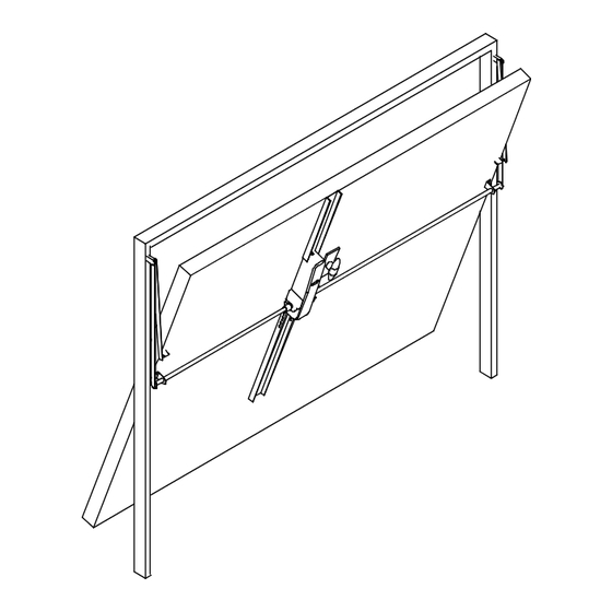
MEASURES TO BE RESPECTED INSTALLATION OF CENTRAL SINGLE INSTALLATION OF LATERAL DOUBLE MOTOR MOTOR UP & OVER DOOR SUPPORTING FRAME In both central single motor and lateral double motor, the condition described in the figure is equally defined. -
Page 6: Installing The Gearmotor
INSTALLING THE GEARMOTOR Valuate the anchoring position of the gear motor based on the dimensions shown in the figure; fasten the stud-bolt with the relative washer and tighten the nuts. INSTALLATION OF TRANSMISSION AXES FOR CENTRAL SINGLE MOTOR After having cut the transmission axes to the agreed length, fasten them to the shaft of the gear motor by means of proper pegs;... -
Page 7: Installing The Telescopic Arms
INSTALLING THE TELESCOPIC ARMS CENTRAL SINGLE MOTOR LATERAL DOUBLE MOTOR 1. Cut the components of the telescopic arms 1. Cut the components of the telescopic arms and anchor them to the transmission axis. and anchor them. ADJUSTING THE END-LIMIT SWITCHES In case the installed automation is made up by a central- motor, the stroke of the tilting gate is adjusted by acting on the stops (1), and by rotating them in the ring that seats... -
Page 8: Manual Unlock
MANUAL UNLOCK To enable the manual release, introduce the key in the unblocking spindle and rotate it about 90° clockwise, as shown in the figure. Thanks to the external manual release available on request, it is also possible to enable the manual release from the exterior by rotating the handle of the tilting gate;... -
Page 9: Typical System
TYPICAL SYSTEM MAIN COMPONENTS 1 – GEARMOTOR 2 – KEY SELECTOR 3 – SWITCH 4 – FLASHING LIGHT 5 – PNEUMATIC EDGE... -
Page 10: Use
It is absolutely forbidden to use the device for any other purposes. The installed control board (which must have built-in electric friction), allows to select the following functions: automatic: one control impulse will open or close the tilting gate; semi-automatic: one control impulse will open or close the tilting gate. In case of blackout, act on the manual unlocking device and move manually tilting gate. -
Page 11: Tilting Gates Installation Guide
TILTING GATES INSTALLATION GUIDE IN ACCORDANCE WITH REGULATION 98/37/CE ON MACHINERY AND WITH REGULATION EN 12453 – EN 12445 Hazard areas of the tilting gate (figure 1) LEGEND OF MECHANICAL RISKS CAUSED BY MOVEMENT In accordance with the Regulation on Machinery, the following de nitions are applicable: −... - Page 12 MINIMUM LEVEL OF PROTECTION FOR THE MAIN EDGE Mode of Use Type of Activation Controls Informed Users Informed Users Uninformed Users (private area) (public area) □ □ The man-operated Button command Turnkey button Man-operated Command command is not command allowed □...
- Page 13 [3] Impact and crashing on the lower retaining edge (figure 1, risk A) □ Measure the closing stress (with the proper tool required by regulation EN 12445) as indicated in the figure. Check that the values measured by the instrument are less than the ones indicated in the graphic.
- Page 14 [5] Impact and crashing on the lower retaining edge ( gure 1, risk A) Install two photo-cells (recommended height: 200 mm) to detect the presence of the test parallelepiped (height 300 mm) positioned as indicated in the gure. In case of a tilting gate installed in a private residence, which does not face onto a public area, and does not work with time automatic closing, the photocell is not compulsory.
- Page 15 Evaluation Criteria and Solutions to Adopt Types of Risks Annex (Check the box corresponding to the solution adopted) □ [9] Impact, crashing, The sliding lateral guides (necessary for operating the system) must have a cutting on the sliding minimum opening, so as not to allow the introduction of hands, which must not lateral guides of the come into contact with the gate's suspension systems (counterweights, strap moving gate (figure 1,...
- Page 16 Evaluation Criteria and Solutions to Adopt Types of Risks Annex (Check the box corresponding to the solution adopted) □ [14] Safety conditions Use activation groups in accordance with regulation EN 12453 and safety in case of power devices in accordance with regulation EN 12978. failure □...
- Page 17 Evaluation Criteria and Solutions to Adopt Types of Risks Annex (Check the box corresponding to the solution adopted) Safety and Information Integration Principles □ [21] Notification Means 1.7.1 Install the blinker in a visible position to signal the movement of the door. □...
-
Page 18: Maintenance Record Book
Technical Assistance: MAINTENANCE RECORD BOOK (Name, address, telephone) This Maintenance Record Book contains technical information as well as a list of installations, maintenance and repairs performed and must be available for possible inspections by authorized bodies. TECHNICAL DATA AND INSTALLATION OF THE MOTORIZED DOOR/GATE Customer: _____________________________________________________________ Name, Address, Contact Person... - Page 19 LIST OF RESIDUAL RISKS AND IMPROPER, FORESEEABLE USE Noti cation through signs posted on the product’s danger points and/or through written notices to deliver to and explain to the user or the person in charge about the existing risks and the improper, foreseeable use. _____________________________________________________________________________________________ _____________________________________________________________________________________________ _____________________________________________________________________________________________...
- Page 20 DECLARATION OF CONFORMITY (OF THE MANUFACTURER) Manufacturer: QUIKO ITALY SAS Via Seccalegno, 19 36040 Sossano (VI) Italia hereby declares, under his liability, that the products: QK-B220, QK-B24 are in compliance with the essential safety requirements of the regulations: Electromagnetic Compatibility Directive ......2004/108/EC Low Voltage Directive ............2006/95/EC...
- Page 21 DECLARATION OF CONFORMITY (OF THE INSTALLER) The undersigned: Address: in charge of the set-up, declares that the product: Gate type: Location: are in compliance with the essential safety requirements of the regulations: Electro magnetic Compatibility Directive ......2004/108/EC Low Voltage Directive ............2006/95/EC Machinery Directive ..............2006/42/EC and also declares that the related and/or specific national technical regulations have been followed:...
- Page 24 QUIKO ITALY Via Seccalegno, 19 36040 Sossano (VI) - Italy Tel. +39 0444 785513 Fax +39 0444 782371 info@quiko.biz www.quikoitaly.com The Manufacturer can technically improve the quality of its products without any prior notice.
Need help?
Do you have a question about the QK-B220 and is the answer not in the manual?
Questions and answers