Table of Contents
Advertisement
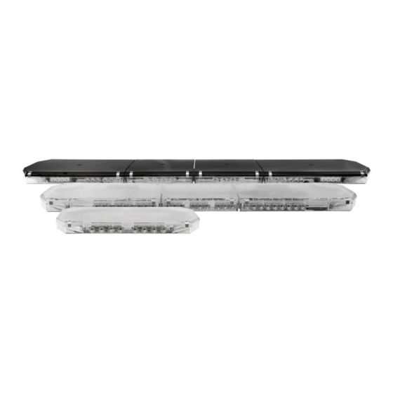
ECCO 21 Series Lightbars are versatile and powerful warning devices that offer numerous lighting module and length options. The 21
Series is suitable for many vehicle applications and features a durable aluminum chassis, polycarbonate lenses and a sleek, low profile
design. These lightbars can either be mounted permanently to the vehicle or using an optional, semi-permanent roof mounting kit. There
are two types of 21 Series lightbar - IF (independent flashing) and CC (centrally controlled). IF (Independent Flashing) indicates the
lightbars modules have individual electronic circuits that control their operation, each module, a group or a pair of modules can be controlled
independently. CC (Centrally Controlled) indicates the lightbar's modules are controlled by a centralized electronic driver board which
provides simpler and greater programming flexibility of all lightbar functionality.
Unpacking and Pre-Installation:
Carefully remove the lightbar and place it on a flat surface. Examine the unit for transit damage and locate all parts. If damage is found or
parts are missing, contact the transit company or ECCO. Do not use damaged or broken parts.
Ensure the lightbar voltage is compatible with the planned installation.
IMPORTANT!
Read all instructions before installing and using. Installer: This manual must be
delivered to the end user. This manual assumes installation by a suitably qualified Automotive Technician.
Installation and Operation Instructions
21 Series Multicolor Lightbars
Page 1 of 20
Advertisement
Table of Contents

Related Manuals for Ecco 21 Series


Summary of Contents for Ecco 21 Series
- Page 1 21 Series Multicolor Lightbars ECCO 21 Series Lightbars are versatile and powerful warning devices that offer numerous lighting module and length options. The 21 Series is suitable for many vehicle applications and features a durable aluminum chassis, polycarbonate lenses and a sleek, low profile design.
- Page 2 WARNING! Failure to install or use this product according to manufacturer’s recommendations may result in property damage, serious bodily/personal injury, and/or death to you and those you are seeking to protect! Do not install and/or operate this safety product unless you have read and understand the safety information contained in this manual.
- Page 3 Permanent Mounting with Adjustable Mounting Feet 1. Loosen the 5/16” nuts to allow the mounting feet to slide along the base. Place the lightbar over the center of the vehicle and slide the mounting feet into position near the curved edges of the roof when possible. 2.
- Page 4 Permanent Mounting without Adjustable Mounting Feet 1. Insert the four 5/16”-18 carriage bolts in the channels on the under side of the lightbar. 2. Place the lightbar over the center of the vehicle and slide the mounting hardware into position near the curved edge when possible as shown in FIGURE 4.
- Page 5 Pylon/Headache Rack Mounting 1. Insert the four (4) 5/16”-18 carriage bolts in the channels on the under side of the lightbar and loosely attach the mounting brackets. 2. Place the lightbar on the vehicle and slide the mounting brackets into position. 3.
- Page 6 Strap Kit Mounting Important! Mounting brackets are specific to the vehicle model. Please make sure the brackets are suitable for the vehicle before installation. 1. Loosen the 5/16” nuts to allow the mounting feet to slide along the base of the lightbar. Loosely attach the mounting strap to each foot using the supplied pan head phillips screws and lock washers.
- Page 7 Wiring A multicolor LED CC series lightbar has a 2-wire power cable and a 16-wire control cable. The entire power load of the bar goes through the power cable. The black ground wire should be connected directly to the battery. The 10 AWG red power wire requires a constant 10 to 16V power source with a customer supplied in line fuse.
- Page 8 Emergency Mode Flash Pattern Selection There are seven customizable emergency flash pattern modes available based on the wire combinations shown in Table 2. When using individual switches, make sure to configure all possible switch combinations. The default flash setting is unsynchronized which allows each module group to be configured separately and the lightbar to flash in an unsynchronized pattern.
- Page 9 Multicolor Module LED Color Hierarchy Color Combination Primary Secondary RED/BLUE BLUE RED/AMBER AMBER RED/WHITE WHITE BLUE/AMBER BLUE AMBER BLUE/WHITE BLUE WHITE AMBER/WHITE** AMBER WHITE TABLE 4 **For AMBER/WHITE modules within the Arrowstik, WHITE is primary and AMBER is secondary. To change a Module group flash pattern selection: 1.
- Page 10 For best results, modules groups with one or more single color modules should be set to primary only flash patterns. For instructions related to the California Title 13 steady burning red warning lamp requirement during level mode operation, please contact ECCO directly. Page 10 of 20...
- Page 11 Emergency Mode Flash Pattern Selection – Synchronized The seven customizable emergency flash pattern modes each have the option to be synchronized. This condenses the module groups from Table to front and rear. The default flash sequences are shown below in Table 7. Level Mode Default Sequence by Group - Synchronized Module Group Front...
- Page 12 After the module groups have a sequence selected, a flash pattern rate can be chosen. The default rates are as follows in TABLE 10. Level Mode Default Flash Rate by Module Group - Synchronized Module Group Front Quad 75 FPM Quad 75 FPM Cycle Rear...
- Page 13 Arrowstik Flash Pattern Selection The CC Series Lightbar is designed to offer user selectable traffic directing and traffic warning flash patterns. Each of the ArrowStik® func- tions (LEFT, CENTER-OUT, RIGHT or FLASH) can be programmed individually for unique sequences and flash rates. This allows the great- est flexibility when controlling the various lightbar configurations available.
- Page 14 Arrowstik Emergency Mode Operation ArrowStik Emergency Mode adds an alternating double flash sequence of the primary LEDS after the Arrowstik sequence cycles four times. The lightbar will come from the factory, with the ArrowStik Emergency function disabled. This option is only available for lightbars with multicolor modules in the Arrowstik. Please note that this function does not work with the FLASH function.
- Page 15 To enable a secondary cruise, takedown, work and alley light flash function: 1. Power-up the lightbar and apply +power to one wire from Table 17 that will be changed to a secondary mode. Programming will not work if more than one function is selected at a time. 2.
- Page 16 Secondary Right or Left Alley Light Flash Patterns Order Modules Standard Alley Light Function Alley, Front Corner Alley, Rear Corner Alley, Front and Rear Corners TABLE 20 Secondary Cruise Mode Modules Order Modules LEDs Corners - Dim (Standard Cruise Function) Primary Only Corners - Dim Secondary Only...
- Page 17 Options and Maintenance: Lens Cleaning Occasional cleaning of the lenses will ensure optimum light output. Take care when cleaning lenses - although tough, polycarbonate scratches easily. Clean the lens and base with soap and water or a lens polish using a soft cloth. Do not use solvents as they may damage the polycarbonate.
- Page 18 Replacement Parts/Accessories: Description Part No. Lenses Lower end EZ2101C Lower mid/center short (8”/203mm) EZ2108C Lower mid/center medium (11”’/280mm) EZ2111C Lower mid/center long (16”406mm) EZ2116C Upper mid/center medium, (11”/280mm) EZ2127U11X* Upper mid/center long, amber (11”/280mm) EZ2127U16X* 22”/0.7m (upper) EZ2127U22X* Upper mid/center short (8”/203mm) EZ2127U8X* Upper end EZ2127UX*...
- Page 19 Troubleshooting: All lightbars are thoroughly tested prior to shipment. However, should you encounter a problem during installation or during the life of the product, follow the guide below for troubleshooting and repair information. If the problem cannot be rectified using the solutions given below, additional information may be obtained from the manufacturer –...
- Page 20 Manufacturer Limited Warranty and Limitation of Liability: Manufacturer warrants that on the date of purchase this product will conform to Manufacturer’s specifications for this product (which are available from the Manufacturer upon request), and Manufacturer further warrants that this product is free from defects in materials and workmanship. This Limited Warranty extends for Sixty (60) months from the date of purchase.
Need help?
Do you have a question about the 21 Series and is the answer not in the manual?
Questions and answers