Table of Contents
Advertisement
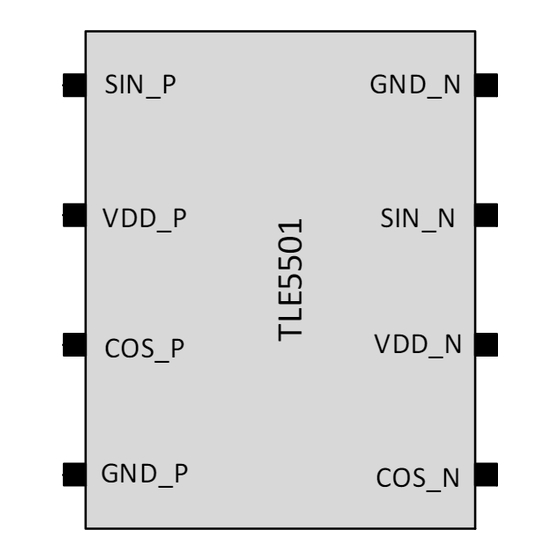
T L E 5 5 0 1
TMR-Base d Angle Sensor
User's Manual
About this document
Scope and purpose
This document covers the TMR angle sensor TLE5501 with its versions E0001 and E0002.
Intended audience
This document is aimed at experienced hardware and software engineers using the TLE5501 angle
sensor
User's Manual
1
Rev. 1.0
www.infineon.com/sensors
2019-04-29
Advertisement
Table of Contents

Related Manuals for Infineon TLE5501 Series


Summary of Contents for Infineon TLE5501 Series
- Page 1 Scope and purpose This document covers the TMR angle sensor TLE5501 with its versions E0001 and E0002. Intended audience This document is aimed at experienced hardware and software engineers using the TLE5501 angle sensor User’s Manual Rev. 1.0 www.infineon.com/sensors 2019-04-29...
-
Page 2: Table Of Contents
TLE5501 TMR-Based Angle Sensor Table of Contents Application Circuits ............. . . 3 Transient behavior . -
Page 3: Application Circuits
TLE5501 TMR-Based Angle Sensor Application Circuits Application Circuits The application circuits in this chapter show the various connection possibilities of the TLE5501. It can be used in a single ended mode (only one sine and one cosine signal, Figure 1 Figure 3) and in a differential mode with a total of four output signals... - Page 4 TLE5501 TMR-Based Angle Sensor Application Circuits SIN_P SIN_P GND_N VDD_P VDD_P SIN_N COS_P VDD_N COS_P 100n GND_P GND_P COS_N Figure 3 Application circuit for TLE5501 E0002 single ended signal used SIN_P GND_N SIN_P GND_N VDD_P VDD_P SIN_N SIN_N 100n 100n VDD_N COS_P COS_P...
-
Page 5: Transient Behavior
TLE5501 TMR-Based Angle Sensor Transient behavior Transient behavior For the sine and cosine output pins, it is also recommended to use a buffer capacitor C for filtering purpose. As the device itself has a high output impedance, given by the TMR resistors R , this buffer capacitor builds a low-pass filter together with the bridge resistivity. - Page 6 TLE5501 TMR-Based Angle Sensor Transient behavior 3.00 2.50 2.00 1.50 1.00 pSPICE analyt. R = 4k 0.50 analyt. R = 8k 0.00 0.0E+00 5.0E-06 1.0E-05 1.5E-05 2.0E-05 2.5E-05 3.0E-05 3.5E-05 time (s) Figure 6 Simulation (pSPICE and analytical) of the RC behavior of the output voltage (R = 8kΩ, C = 1nF).
- Page 7 TLE5501 TMR-Based Angle Sensor Transient behavior 1.00 0.90 Ampl. pSPICE Ampl. analyt. 0.80 0.70 0.60 0.50 0.40 0.30 0.20 0.10 0.00 1000 10000 100000 frequency (Hz) Figure 7 Normalized output amplitude for an AC magnetic field excitation. Bridge resistor R 8kΩ, C =1nF.
- Page 8 TLE5501 TMR-Based Angle Sensor Transient behavior For a bridge resistivity of R = 8kΩ and a buffer capacitor of C = 1nF, the cut-off frequency f is calculated according to Equation (2.4) with R = R (2.4) -------------- - ------------------------- - 39.78kHz πR TMR C 2πRC...
-
Page 9: Recommendation For The External Capacitor C
TLE5501 TMR-Based Angle Sensor Transient behavior For the time τ until the voltage settles to a value less than 0.5LSB from final value U the following relation holds: (2.7) æ æ ö ö τ s τ b r ⋅ ------ - –... -
Page 10: Connection To A Micro Controller
TLE5501 TMR-Based Angle Sensor Connection to a micro controller Connection to a micro controller The following chapters give some hints which should be considered when the TLE5501 is connected to a microcontroller. Sigma-Delta ADC In a Sigma-Delta ADC, the analog input signal is converted into a bit stream with the bit density corresponding to the analog input value. -
Page 11: Load Step
TLE5501 TMR-Based Angle Sensor Connection to a micro controller TMR bridge Figure 10 Equivalent circuit of TMR bridge (only half bridge is shown) and SAR ADC input 3.2.1 Load step The following consideration is made with the initial condition that the buffer capacitor C is fully charged, the S/H switch is open and the sample and hold capacitor C is decharged. - Page 12 TLE5501 TMR-Based Angle Sensor Connection to a micro controller After 36µs the capacitors C and C are almost fully charged, the S/H switch is opened and the ADC can start with the conversion and will sample the correct voltage of V /2.
-
Page 13: Load Step Reduction
TLE5501 TMR-Based Angle Sensor Connection to a micro controller 1,000 100000 f_sample f_rotation 10000 1000 10.0 100.0 (nF) Figure 12 Sampling frequency f and sensor bandwidth f as function of the buffer capacitor sample rotation is assumed to be 8kΩ. 3.2.2 Load step reduction As seen in... -
Page 14: Oversampling
TLE5501 TMR-Based Angle Sensor Connection to a micro controller 3.2.3 Oversampling As seen in Chapter 3.2.1 the sampling frequency f is mainly given by the buffer capacitor C . In some sample cases, it might be necessary to perform an oversampling, i.e. to measure the same value several times and calculate the average to increase resolution. -
Page 15: Calibration
TLE5501 TMR-Based Angle Sensor Calibration Calibration Before the TLE5501 can be used in an application, a calibration on system level has to be performed. The four analog output signals SIN_P, SIN_N, COS_P, COS_N have usually an offset and an amplitude mismatch. This has to be corrected before the angle can be calculated. - Page 16 TLE5501 TMR-Based Angle Sensor Calibration Therefore, the following relation has to be ensured by the user over the complete lifetime: = 0.9B < B < 1.1B ; with B : magnetic field at 25°C/0h and B : minimum and maximum magnetic field at initial calibration condition (25°C) over lifetime The temperature behavior of B and B...
- Page 17 TLE5501 TMR-Based Angle Sensor Calibration 0.35 33.8mT 50.8mT 49.1mT 36.0mT 39.6mT 0.25 47.2mT 42.8mT 45.0mT 50mT Initial calibration 0.15 temperature ( ° C) Figure 16 Typical angle error with initial calibration at 25°C/50mT and subsequent measurements considering 10% magnetic field change due to aging and air gap variation (i.e. 45mT @25°C). Magnetic field values change with a TC of -2000ppm/K (ferrite magnet material).
-
Page 18: Revision History
TLE5501 TMR-Based Angle Sensor Revision History Revision History Revision Date Changes 2019-04-29 Initial version User’s Manual Rev. 1.0 2019-04-29... - Page 19 Infineon Technologies, The data contained in this document is exclusively Infineon Technologies’ products may not be used in intended for technically trained staff. It is the Document reference any applications where a failure of the product or any responsibility of customer’s technical departments to...
Need help?
Do you have a question about the TLE5501 Series and is the answer not in the manual?
Questions and answers