
Related Manuals for Keysight Technologies N5261A


Summary of Contents for Keysight Technologies N5261A
- Page 1 Keysight Technologies N5261A and N5262A Millimeter Head Controller User's and Service Guide...
- Page 2 Limited Rights as defined in FAR agreement and written consent 27.401 or DFAR 227.7103-5 (c), as U.S. Government Rights from Keysight Technologies, Inc. as applicable in any technical data. governed by United States and The Software is “commercial international copyright laws.
-
Page 3: Table Of Contents
Available Fuses Network Analyzer Requirements System Configurations PNA Based Configurations PNA-X Based Configurations System Accessory Information N5261A Interface Kits N5262A Interface Kits Test Set to the Module Cable Sets Compatible mm-wave Modules Available OML Modules Available VDI Modules Cable Loss Between the Test Set and the Module... - Page 4 2 Service Information 49 Part Replacement and Location Information Replaceable Parts Test Set Diagrams and Graphics Theory of Operation Functional Block and Assembly Information Troubleshooting the Test Set Troubleshooting, DC Level Power Supply and Fans Overcurrent LEDs are ON (Amber) Front Panel Active and Port Status LED Troubleshooting, RF Level RF Out Failures...
- Page 5 2 Service Information claration of Conformity Statement of Compliance Before Applying Power Connector Care and Cleaning Precautions Regulatory Information Instrument Markings Battery Collection Electrical Safety Compliance EMI and EMC Compliance Electrical Discharge Protection Keysight Support, Services, and Assistance Contacting Keysight Shipping Your Product to Keysight for Service or Repair Keysight N5261/62A User’s &...
-
Page 7: Chapter 1 - Installation And System Operation
Installation & System Operation Keysight N5261/62A User’s & Service Guide... -
Page 8: Introduction
Installation & System Operation Introduction This section of this document describes system installation and operation of the N5261A/N5262A Millimeter Module Controller. Figure 1-1 2-Port Banded Millimeter-wave Configuration (N5261A) Figure 1-2 4-Port Banded Millimeter-wave Configuration (N5262A) Figure 1-2 Keysight N5261/62A User’s & Service Guide... -
Page 9: Description
N5251A broadband analyzer system. This application is not discussed in this manual. Refer to N5251-90001 for N5251A system information. In this document the N5261A and N5262A will be referred to as the test set. This manual should be used in conjunction with the following documents: —... -
Page 10: Test Set Accessories
Use the tables below to verify that your shipment is complete. Table 1-1 N5261/62A Standard Content √ Keysight Ref Des Description Part Number N5261A or Millimeter Head Controller Test Set N5262A 1810-0118 Coax Termination, 50 Ohm, male (load) (N5261A) 1810-0118 Coax Termination, 50 Ohm, male (load) -
Page 11: General Specifications
100/120/220/240 Vac N5261A or N5262A Power 350 Watts (Max.) Weight and Dimensions: Net Weight N5261A 10 kg (22 lb) N5262A 11 kg (24.2 lb) Dimensions Height: 18 cm (7.1 in) Width: 42.5 cm (16.75 in) Depth: 42.5 cm (16.75 in) This product is designed for use in Installation Category II and Pollution Degree 2. - Page 12 Installation & System Operation Table 1-3 Characteristics and Specifications Power Levels (dBm) Gain Frequency Front/Rear Panel Connector N5261A TEST or REF IF (Input) (characteristic) 7.6 MHz − −27 −10 − TEST IF to A/B/C/D IF OUTPUT (specification) −1.5 dB (± 1) 7.6 MHz...
-
Page 13: Front Panel Features
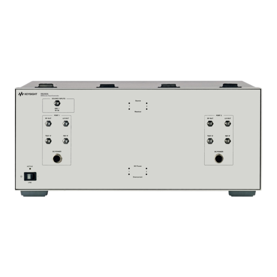
Installation & System Operation Front Panel Features Figure 1-3 N5261A (2-Port) Front Panel Features LO Out SRC1 Input Port Status LEDs RF Out Ref IF Test IF Active Standby Switch Over Current LEDs DC Power Figure 1-4 N5262A (4-Port) Front Panel Features... - Page 14 (illuminated). The LED is Off (not illuminated) when the test set is in Standby, or not addressed by the analyzer. The SRC2 Input and Ports 3 and 4 features are not present on the N5261A. Refer to Figure 1-1 on page...
-
Page 15: Rear Panel Features
Installation & System Operation Rear Panel Features Figure 1-5 N5261A Rear Panel Features IF Outputs D, C, B, A LO IN SRC1 IN/OUT Line Module Test Set I/O Pass Thru Interface Chassis Ground Figure 1-6 N5262A Rear Panel Features IF Outputs... - Page 16 — C (from the test set to the analyzer’s IF C Input) — R (from the test set to the analyzer’s IF R Input, not installed in the N5261A) — A (from the test set to the analyzer’s IF A Input) —...
-
Page 17: Available Fuses
Installation & System Operation Power Cords A line power cord is supplied in one of several configurations, depending on the destination of the original shipment. Keysight can supply additional certified power cords to meet region electrical supply and receptacle configurations. Please refer to our website at: http://www.keysight.com assistance in power cord selection. -
Page 18: Network Analyzer Requirements
Installation & System Operation Network Analyzer Requirements The required options for PNA models are indicated in the “PNA Option(s)” column of Table 1-4. The required options for PNA-X models are indicated in the “PNA Option(s)” column of Table 1-5. Note that all models require Option 020. -
Page 19: System Configurations
System Configurations Table 1-4 Table 1-5 document all supported configurations for S-Parameter measurement capabilities for banded mm-wave systems using the N5261A and N5262A test sets. Capabilities: [C1]=pulse, [C2]=power control/RCVR leveling, [C3]=SMC+phase, [C4]=SPM, [C5]=ITSMA Table 1-4 PNA Based Configurations PNA Model... -
Page 20: Pna-X Based Configurations
Installation & System Operation Table 1-5 PNA-X Based Configurations PNA-X Test Set Cable Interface Cable Capabilities and Model (s) Connects Config. Notes Option(s) Diag(s) N5242A/B N5261A front N5261A-102 [C1,C2,C3,C4__] N5262A front N5262A-102 [C1,C2__C4,__] 200 & 224 N5261A front N5261A-102 [C1,C2,C3,C4__] rear N5261A-102... - Page 21 Installation & System Operation Table 1-5 PNA-X Based Configurations (Continued) PNA-X Test Set Cable Interface Conn. Capabilities and Model (s) Connects Notes Option(s) Diag(s) N5247A/B N5261A front N5261A-112 [C1,C2,C3,C4__] rear N5261A-102 [C1,C2,C3,C4__] N5262A front N5262A-112 [C1,C2,C3,C4__] rear xxxx xxxx config not available 200 &...
-
Page 22: System Accessory Information
Coax Rigid CA-Assy, SMA (m/f), (SRC1 to Port 1 PNA) U3021-60002 Lock Link Kit, Test Set to PNA-X N5261A Option 104 (Interface Kit for the 4-Port PNA N5222/42A/B) 5061-9038 Coax Flex CA-Assy - SMA (m/m), 520 mm (20 in), rear panel connections... -
Page 23: N5262A Interface Kits
Table 1-6 N5261A to the Module Cable Set Options (Continued) U3021-60003 Lock Link Kit, Test Set to PNA N5261A Option 114 (Interface Kit for the 4-Port N5227/47A/B) 5061-9038 Coax Flex CA-Assy - SMA (m/m), 520 mm (20 in), rear panel connections N5262-20026 Coax Rigid CA-Assy, SMA male to 2.4 mm female... - Page 24 Installation & System Operation Table 1-7 N5262A to the Module Cable Set Options (Continued) N5262-20025 Coax Rigid CA-Assy, SMA male to 2.4 mm female (SRC2 to Port 2 PNA) N4903-61250 Coax Adapter (3.5 mm female to 2.4 mm male) U3021-60003 Lock Link Kit, Test Set to PNA N5262A Option 108 (Interface Kit for the 4-Port N5224/25/44/45A/B) 5061-9038...
-
Page 25: Test Set To The Module Cable Sets
Installation & System Operation Table 1-8 Test Set to the Module Cable Set Options (Sold Separately) Keysight Description √ Part Number N5261/62A Option 501 (1-Port Trans/Refl Cable Set (48 inches = 1.2 meter)) 1250-2604 Coax Connector Adapter, right angle- SMA m/f 8121-1221 Coax flex CA-Assy, 3.5 mm male to male, 1.2 m (48 in) - RF &... -
Page 26: Compatible Mm-Wave Modules
Installation & System Operation Compatible mm-wave Modules Keysight offers millimeter modules manufactured by Olsen Microwave Labs (OML) and Virginia Diodes Inc (VDI) for use with the N5261/62A for banded mm-wave network analyzer systems. Refer to Table 1-9 on page 21 Table 1-10 on page Transmission/Reflection millimeter-wave modules contain an RF source multiplier, dual directional coupler, reference downconverter and a test... -
Page 27: Available Oml Modules
Installation & System Operation Table 1-9 Available OML Modules Banded Freq Port Type Source Receiver Model # Notes Ranges (GHz) 33 to 500 Waveguide √ √ N5256AWxx T/R Module 33 to 500 Waveguide √ N5257ARxx Receiver 33 to 500 Waveguide Dual N5258ADxx Receiver-Dual... -
Page 28: Cable Loss Between The Test Set And The Module
Installation & System Operation Cable Loss Between the Test Set and the Module If the cables between the test set and the millimeter-wave modules are longer than four feet, cable loss for the RF and LO paths may be excessive. Perform the analysis recommended below. -
Page 29: System Configuration And Operation
Installation & System Operation System Configuration and Operation Site Preparation Install the instrument so that the detachable power cord is readily identifiable and is easily reached by the operator. An externally installed switch or circuit breaker (which is readily identifiable and is easily reached by the operator) should be used as the disconnecting device.The detachable power cord can also be used to disconnect the mains circuits from the mains supply before other parts of the instrument. -
Page 30: System Setup
Installation & System Operation System Setup It is recommended that you connect the cables to the rear panel of the test set before mounting the analyzer on top of the test set. When the analyzer is mounted on the test set, the back of the analyzer extends over the rear panel of the test set and may interfere with access to the rear panel connectors. - Page 31 Installation & System Operation Figure 1-10 Rear Bottom Feet Standoffs (x2) Feet (x4) 3. Install the two rear locking feet from the (5023-0132) onto the analyzer, where the standoffs were removed. Figure 1-11 Install Locking Feet on Network Analyzer Locking Foot from Kit (5023-0132) 4.
- Page 32 Installation & System Operation Figure 1-12 Rear Locking Feet (N5222A/B or N5242A/B) N5242-20139 N5242-20138 0515-2317 (x2) Keysight N5261/62A User’s & Service Guide...
- Page 33 Installation & System Operation 6. Place the analyzer on top of the test set and ensure that the front frame of the analyzer is positioned slightly forward of the locks that are attached to the test set. Slide the analyzer back so the locks engage the front frame of the analyzer.
- Page 34 Installation & System Operation Figure 1-14 Locking Feet Screws Locking Screw Locking Screw N4011-21002 Keysight N5261/62A User’s & Service Guide...
-
Page 35: Rear Panel Connections
Figure 1-20. Refer to Table 1-4 on page 13 Table 1-5 on page 14 to determine which figure applies to your configuration. Figure 1-15 N5261A Rear Panel Configuration A From: D/R2 C/R1 Test Set I/O LO OUT (J5) PNA/PNA-X To: N5261A... - Page 36 Installation & System Operation Figure 1-16 N5262A Rear Panel Configuration B From: D/R2 C/R1 Test Set I/O LO OUT (J5) PNA/PNA-X To: N5262A Test Set I/O LO IN Controller Keysight N5261/62A User’s & Service Guide...
- Page 37 Installation & System Operation Figure 1-17 N5261A Rear Panel Configuration C From: D/R2 C/R1 Test Set I/O LO OUT (J5) SW SRC PNA/PNA-X OUT (J11) To: N5261A Test Set I/O LO IN SRC 1 RF IN (Port1 Controller SW SRC) 1.
- Page 38 Installation & System Operation Figure 1-18 N5262A Rear Panel Configuration D From: D/R2 C/R1 Test Set LO OUT SW SRC SW SRC PNA/PNA-X (J5) OUT (J8) OUT (J11) To: N5262A Test Set LO IN SRC 2 RF IN (SRC SRC1 RF IN Controller 2 SW SRC) (Port 1 SW SRC)
- Page 39 Installation & System Operation Figure 1-19 N5261A Rear Panel Configuration E From: D/R2 C/R1 Test Set I/O LO OUT (J5) RF 1 OUT PNA/PNA-X (J6) To: N5261A Test Set I/O LO IN SRC 1 RF IN (Port Controller 1 SW SRC)
- Page 40 Installation & System Operation Figure 1-20 N5262A Rear Panel Configuration F From: D/R2 C/R1 Test Set LO OUT (J5) RF 2 OUT RF 1 OUT PNA/PNA-X (J12) (J6) To: N5262A Test Set LO IN SRC 2 RF IN SRC1 RF IN Controller (SRC 2 SW SRC) (Port 1...
-
Page 41: Pna And Pna-X Front Panel Connections
Figure 1-21 Figure 1-22 provide the connection diagrams. Figure 1-21 N5261A Front Panel Configuration Y and Z B. N5262-20018, -20026 (W1) A. N5262-20016, -20023 (W1) Figure 1-22 N5262A Front Panel Configuration V and X C. N5262-20016, -20023 (W1) E. -
Page 42: Millimeter-Wave Module Cable Connections
Installation & System Operation Millimeter-wave Module Cable Connections Before connecting the millimeter-wave modules, verify that the test set and the power supplies (if used) are powered down. There are four RF cables for each T/R module. Cables provided with the VDI modules are pre-labeled. - Page 43 Installation & System Operation The following detailed instructions are for connecting an OML T/R module. These instructions assume a cable dress kit (black sleeving) is available. Modify the instructions appropriately for other types of modules. 1. Prepare the cable bundle comprised of five cables listed in Table 1-13.
- Page 44 Installation & System Operation 4. Select a Millimeter-wave module and place it on the work surface in front of the test set. 5. Connect the bundle of cables to the module in the following order. Millimeter Head Connections Table 1-14 Order Module (OML) +12 V...
-
Page 45: Configuring The Network Analyzer Firmware
Installation & System Operation Configuring the Network Analyzer to Millimeter Mode This section will describe how to set up and operate the N5261/62A Millimeter Head Controller with your network analyzer. The N5261/62A Millimeter Head Controller is considered a “slave” instrument. A network analyzer must be used to control the test set. - Page 46 1. Connect your system and turn on all of the equipment. 2. To access the millimeter application select [System] > Configure > Millimeter Module. 3. Select the test set you are using from the drop-down menu (N5261A or N5262A). 4. Click the New command button.
- Page 47 Installation & System Operation 9. Select or clear the "Route PNA RF to rear panel 'RF OUT'” check box as indicated in Table 1-4 on page 13 Table 1-5 on page 10. Set the ALC mode according to the following information: For most applications the ALC mode should be on “Enable Test Set RF ALC”...
-
Page 48: System Operation Verification
— The Banded System Check verifies the configured system is operating correctly. It requires all system components. — If a problem is suspected with the N5261A or N5262A test set, refer to "Part Replacement and Location Information” on page 50 “Troubleshooting the Test Set”... - Page 49 Installation & System Operation Procedure This procedure assumes that you have a Transmission/Reflection module on each port. If not, the procedure will have to be modified appropriately. The Operational Check procedure verifies that the banded system is connected correctly and the modules, test set and analyzer are operating properly. 1.
- Page 50 Installation & System Operation Figure 1-29 Banded System Check 5. Measure a Thru Connection. a. Connect the Port 1 to Port 2 module, and Port 3 to Port 4 module (N5262A) to form thru connections. b. Delete the trace 1, S11. Select Trace/Chan > Trace > Delete Trace. c.
- Page 51 Installation & System Operation Figure 1-30 Uncalibrated S12 and S21 Keysight N5261/62A User’s & Service Guide...
- Page 52 Installation & System Operation 6. Measure the Dynamic Range of each Millimeter-wave module. a. Measure S11 for a 1-Port system, or S12 and S21 for a 2-Port system, or S12, S21, S34 and S43 for a 4-Port system. b. Select [Avg] > IF Band width [10] > [Enter]. c.
-
Page 53: System Level Troubleshooting
Installation & System Operation System Level Troubleshooting If the System Operation Verification procedure fails, perform the following procedure to isolate the problem. Refer to the Keysight PNA Series: firmware, Upgrades, and Support at: http://na.support.keysight.com/pna for further information. To request service, please contact your local service center. In the US, call 800-829-4444. - Page 54 Keysight N5261/62A User’s & Service Guide...
-
Page 55: Service Information
Service Information Keysight N5261/62A User’s & Service Guide... -
Page 56: Part Replacement And Location Information
Service Information Part Replacement and Location Information There are many other repair and calibration options available from the Keysight Technologies support organization. These options cover a range of service agreements with varying response times. Contact Keysight additional information on available service agreements for this product. -
Page 57: Test Set Diagrams And Graphics
Service Information Test Set Diagrams and Graphics Figure 2-1 N5261A Test Set Diagram Keysight N5261/62A User’s & Service Guide... - Page 58 Service Information Figure 2-2 N5262A Test Set Diagram Keysight N5261/62A User’s & Service Guide...
- Page 59 Service Information Figure 2-3 N5261A RF and LO Block Diagram 1. Refer to Figure 2-1 on page 51 for IF paths. Keysight N5261/62A User’s & Service Guide...
- Page 60 Service Information Figure 2-4 N5262A RF and LO Block Diagram N5262A RF Block Diagram Rear Front Panel Panel SRC 2 IN 8 to 19 GHz Solid State Sw. SRC 2 ½ RF Section 5087-7733 Port 3 & 4 RF Amp Isolator Dir Coupler 0955-1595...
- Page 61 Keysight 2-Port PNA Rear Panel Connections IF MUX IF In Port 1 Port 2 SCR 1 Out/In SCR 1 Input IF Out Input Keysight N5261A 2-Port mm-WaveTest Set Controller Amp1 Amp1 Amp1 10dB DIV1 T-IF 1 R-IF 1 ISOL1 ISOL2 T-IF 2...
- Page 62 Service Information Figure 2-7 N5261A Top View Isolator Port 1 & 2 RF Switch Isolator RF Mod/Amp Slope Attn Cable Assy Coupler Power Divider LO Mod/Amp Preamp Interface Bd Test Set Power Supply LEDs Controller Bd Keysight N5261/62A User’s & Service Guide...
- Page 63 Service Information Figure 2-8 Sloped Attenuator Cable Assembly Keysight N5261/62A User’s & Service Guide...
- Page 64 Service Information Figure 2-10 N5262A Top View Isolator (x4) Port 3 & 4 Mod/Amp LO Mod/Amp Slope Atten Cable Assy Test Set Interface Bd Controller Bd. Port 1 & 2 ALC Amp 1. Refer to Figure 2-2 on page 52 for IF cable routing between the Interface board and the front and rear panels.
- Page 65 Figure 2-11 N5261/62A Bottom View Toriod Filter DC Power Wire Harnesses DC Power LED Cable DC Power Dist. Board Fuse Assembly Power Supply Line Module 1. N5261A will only have two DC power wire harnesses. Keysight N5261/62A User’s & Service Guide...
-
Page 66: Theory Of Operation
Theory of Operation Functional Block and Assembly Information The N5261A/62A routes PNA-X LO and RF signals to a millimeter-wave module. This allows the PNA-X to up-convert for a millimeter-wave source and down-convert a received millimeter-wave frequency to an IF frequency 7.6 MHz. - Page 67 Service Information DC Power Board (N5261-60102) The DC Power board provides connection to the power supply and self recovering fuses for each millimeter-wave module supply (+12 volt) on the front panel. The fuses are reset when the N5261/62A is turned off. Power Supply (0950-4729) The power supply (0950-4729) coverts the AC line voltages to DC.
- Page 68 A four-way power divider provides each Port LO Output from the LO amplifier with approximately 7.2 dB attenuation for each LO Out. Two 50 ohm terminators are installed on the unused N5261A divider paths. If a system is configured with a unused port (a 1-Port reflection system for example) the front panel LO Output ports are to be terminated with a 50 ohm load (1810-0118).
-
Page 69: Troubleshooting The Test Set
Service Information Troubleshooting the Test Set For assistance refer to “Keysight Support, Services, and Assistance” on page If the test set is not operating properly, use the following procedures to aid in isolating the problem. Refer to the “Test Set Diagrams and Graphics” starting on page Troubleshooting, DC Level... - Page 70 b. If no DC voltages are present at the front panel, remove the top and bottom covers. c. Inspect the DC Power board (N5261-60002) connections. d. Measure the +12 Vdc (red wires) on the DC Power board. If the +12 Vdc is present, replace the DC power cable from the front panel (N5652-60001).
-
Page 71: Overcurrent Leds Are On (Amber)
Service Information Overcurrent LEDs are On (Amber) 1. Remove all millimeter module connections from the front panel. If the over current LEDs are off, suspect the millimeter module or the DC Power Bias cable. If the LEDs are on continue with step 2 2. - Page 72 Service Information Table 2-1 Interface Board DC Power Distribution Details Ref Des Load DC Voltage DC Source RF Amp1 2, −2, 9, 15, −15 Main PS U22 & U23 RF Amp2 2, −2, 9, 15, −15 Main PS U22 & U23 LO Pre Amp Main PS LO Amp...
-
Page 73: Troubleshooting, Rf Level
Service Information Troubleshooting, RF Level RF Out Failures If the test ports are not switching, or fail the Operational Check the following procedures can be used to verify the failure. The procedures assume power supplies, controller board and front panel LEDs are working. Suspect the switch Interface board, ribbon cable connection or RF switch. -
Page 74: Ref If Or Test If Failure
Table 2-1 on page 66 Figure 2-13 on page 1. N5261A - Verify that the front panel Port 1 & 2 REF and IF coax cables are properly connected to the rear panel (A, B, C and D) and insertion loss is not >... -
Page 75: Power Sensor And Power Meter Preparation
Service Information — Voltmeter — Power sensor and compatible power meter. The power sensor must be capable of measuring from −10 dBm to +15 dBm at a frequency of 8 GHz. A E4413A power sensor may be used. Power Sensor and Power Meter Preparation The power sensor and power meter must be prepared to make measurements at 8 GHz. -
Page 76: Test Set I/O Commands
Service Information Test Set I/O Commands When troubleshooting the Test Set, I/O commands issued by the PNA will be used. Controlling the Test Set Using Test Set I/O Commands A Test Set I/O command may be used when the PNA is connected to the Test Set via the Test Set I/O cable. -
Page 77: Test Set I/O Command List
Service Information Test Set I/O Command List The following commands are available for controlling/reading the test set. The step-by-step commands in the Part Replacement and Location Information procedure require the use of these commands. The user is required to select the appropriate command, depending on the port or function under test. - Page 78 Service Information Measure LO OUT (Gain and Power) Prepare the PNA to measure S12 with a normalization calibration. Refer to “PNA Normalization Calibration” on page 69. Use a frequency range of 8 to 20 GHz and a power level of −10 dBm. The cable on PNA Port 2 must be long enough to reach the rear panel of the test set.
- Page 79 Service Information Measure the SRC1 & SRC2 RF Paths The following procedure verifies SRC1 and SRC2 internal cables between the front and rear panels. Prepare the PNA to measure S12 with a normalization calibration using a frequency range of 8 to 20 GHz and a power level of −8 dBm. See “PNA Normalization Calibration”...
- Page 80 Service Information 3. Set the PNA power output level to get a power meter reading of 2 dBm ± 1dB. 4. Connect the PNA Port 2 cable to SRC1 RF IN on the front panel. 5. Issue the Test Set I/O commands 32,0 and 0,1 (enable ALC and output to Port 1).
- Page 81 Service Information Measuring Test IF and REF IF Path Loss on the N5261A The IF paths for the N5261A are not switched, see Figure 2-1 on page The cable connected to PNA Port 1 must be long enough to reach the rear panel of the test set.
- Page 82 16,4 Port 2 REF IF 16,2 Port 3 REF IF 16,2 Port 3 REF IF 16,56 Port 4 REF IF 16,1 Port 4 REF IF 16,20 1. Commands are not required for the N5261A. Keysight N5261/62A User’s & Service Guide...
- Page 83 Service Information Figure 2-17 Test IF Path to A, B, C or D (N5262A) Figure 2-18 Ref IF to A, B, C or D (N5262A) Figure 2-19 Ref IF to R (N5262A) Keysight N5261/62A User’s & Service Guide...
-
Page 84: Test And Adjustment Procedures
Service Information Test and Adjustment Procedures “Test Set Operation Check” on page 68 should be performed whenever any active electronic part is replaced in the test set. Additional procedures are required when certain components are replaced. Table 2-4 indicates when additional procedures are required. The additional procedures depend on the location of the replaced component. -
Page 85: Gain Factors In The Src Rf Paths
Typically the gain factors must be updated whenever one or more of the components in an “RF Section” of Figure 2-3, “N5261A RF and LO Block Diagram” Figure 2-4, is replaced. - Page 86 Service Information 11. Move the PNA Port 1 cable to Test Set Port 2 RF OUT. 12. Record the values for Port 2 in Table 2-5 on page 81 Keysight N5261/62A User’s & Service Guide...
- Page 87 Service Information Measure Gain Factors for Ports 3 and 4 (Procedure B) Repeat the process above for Ports 3 and 4 with the following modifications: — Connect the SRC2 jumper on the rear panel. — Connect to SRC2 IN in place of SRC1 IN. —...
- Page 88 Service Information Read Gain Factors from the Test Set (Procedure C) Issue a separate Test Set I/O read command for each entry in Table 2-5 on page 81. Record each value as it is read from the test set. As an example, to read the value for Port 2 at 10 GHz, issue the following command: 36.
-
Page 89: Adjust Alc Levels
Service Information Adjust ALC Levels Background When a component is changed in an RF or LO signal path, it is often necessary to adjust the ALC level for the path. See Table 2-4 on page 78 for required adjustments when a part is replaced. PNA and Power Sensor Preparation A power sensor and power meter must be prepared to make measurements at 8 GHz. - Page 90 Service Information ALC level for LO (Procedure S) 1. Prepare the PNA and Power Sensor as described on page 2. Connect PNA Port 2 to LO IN on the rear panel of the test set. 3. Connect the power sensor to Port 1 LO OUT. 4.
-
Page 91: Safety And Information
Service Information Safety and Information Introduction Review this product and related documentation to familiarize yourself with safety markings and instructions before you operate the instrument. This product has been designed and tested in accordance with accepted industry standards, and has been supplied in a safe condition. The documentation contains information and warnings that must be followed by the user to ensure safe operation and to maintain the product in a safe condition. -
Page 92: Before Applying Power
Service Information Before Applying Power Verify that the premises electrical supply is within the range of the instrument. The instrument has an autoranging power supply. If this product is not used as specified, the protection provided by the equipment could be impaired. This product must be used in a normal condition (in which all means for protection are intact) only. -
Page 93: Connector Care And Cleaning Precautions
Service Information Danger of explosion if battery is incorrectly replaced. Replace only with the same or equivalent type recommended. Discard used batteries according to manufacturer’s instructions. For continued protection against fire hazard replace line fuse only with same type and rating. The use of other fuses or material is prohibited. These servicing instructions are for use by qualified personnel only. - Page 94 Service Information To prevent electrical shock, disconnect the Keysight N5261A or N5262A from mains electrical supply before cleaning. Use a dry cloth or one slightly dampened with water to clean the external case parts. Do not attempt to clean internally.
-
Page 95: Regulatory Information
Regulatory Information This section contains information that is required by various government regulatory agencies. Instrument Markings The instruction documentation symbol. The product is marked with this symbol when it is necessary for the user to refer to the instructions in the documentation. The AC symbol indicates the required nature of the line module input power. -
Page 96: Battery Collection
Battery Collection Do not throw batteries away but collect as small chemical waste, or in accordance with your country’s requirements. You may return the battery to Keysight Technologies for disposal. Refer to “Contacting Keysight” on page 92 for assistance. Electrical Safety Compliance... -
Page 97: Electrical Discharge Protection
Service Information Electrostatic Discharge Protection Electrostatic discharge (ESD) can damage or destroy electronic components. The product is shipped in materials that prevent damage from static, and should only be removed from the packaging in an anti-static area ensuring that the correct anti-static precautions are taken. Two types of ESD protection are listed below. -
Page 98: Keysight Support, Services, And Assistance
Keysight for repair. If you wish to send your instrument to Keysight Technologies for service or repair: — Include a complete description of the service requested or of the failure and a description of any failed test and any error message. - Page 99 This information is subject to change without notice. © Keysight Technologies 2011, 2014-2016, 2019 Print Date: May 2019 Supersedes: July 2016 www.keysight.com...
Need help?
Do you have a question about the N5261A and is the answer not in the manual?
Questions and answers