Table of Contents
Advertisement
Quick Links
Advertisement
Table of Contents

Related Manuals for Keysight Technologies M9037A


Summary of Contents for Keysight Technologies M9037A
- Page 1 User Guide Keysight M9037A PXIe Embedded Controller...
- Page 3 WITHOUT NOTICE, IN FUTURE EDI- without prior agreement and written con- www.keysight.com/find/M9037A (prod- TIONS. FURTHER, TO THE MAXIMUM sent from Keysight Technologies, Inc. as uct-specific information and support, EXTENT PERMITTED BY APPLICABLE governed by United States and interna- software and documentation updates) LAW, KEYSIGHT DISCLAIMS ALL WAR- tional copyright laws.
- Page 4 Safety Information Do Not Remove Instrument Cover The following general safety precau- tions must be observed during all Only qualified, service-trained person- phases of operation of this instrument. nel who are aware of the hazards Failure to comply with these precau- involved should remove instrument tions or with specific warnings or oper- covers.
- Page 5 A CAUTION denotes a hazard. It calls attention to an operating pro- The CSA mark is a registered trade- cedure or practice, that, if not cor- M9037A mark of the Canadian Standards Asso- rectly performed or adhered to MSIP-REM-Kst-xxxxx ciation and indicates compliance to could result in damage to the the standards laid out by them.
-
Page 7: Table Of Contents
M9037A Functional Description ........12... - Page 8 Software Application Licenses........50 Using Multiple SSD in a single M9037A ......50 Drivers .
-
Page 9: Introduction
* The M9037A has two 240-pin, RDIMM sockets that support DDR3-1600 REG/ECC RAM sticks. The standard M9037A configuration is a single 4 GB memory module with a factory option to provide either 8 or 16 GB memory. A 32-bit OS system may not be able to address above 4GB memory space. To use the full 16GB memory, a 64-bit OS must be used. -
Page 10: M9037A At A Glance
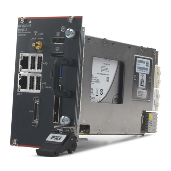
To start the Soft Front Panel interface, from the Window Start menu, under Keysight, look for Embedded Controller SFP. M9037A at a Glance The following figure shows the front panel for the M9037A PXIe Controller. Detailed information about the module follows in this manual. LED Indicators... - Page 11 Both LEDs off indicate that the network link is not established or system is powered off. LAN RST Switch The LAN RST switch is reserved for Keysight use only. Depressing the LAN RST switch has no effect. Keysight M9037A PXIe Embedded Controller User Guide...
-
Page 12: M9037A Functional Description
Introduction M9037A Functional Description M9037A Functional Description Figure 2 M9037A Embedded Controller Functional Block Diagram Keysight M9037A PXIe Embedded Controller User Guide... -
Page 13: Cpu, Memory And Chipset
Other configurations have not been tested. CMOS Backup Battery Keysight’s M9037A is equipped with a 3.0 V “coin cell” lithium battery. This battery powers the clock circuit and retains configuration memory in CMOS RAM while the system is turned off. -
Page 14: I/O Interfaces
M9037A Functional Description I/O Interfaces Keysight’s M9037A provides four USB 2.0 Type A ports and two USB 3.0 Type A ports on the faceplate. All USB ports are compatible with high-speed, full-speed and low-speed USB devices. The M9037A controller supports multiple boot devices. - Page 15 The M9037A has two RJ-45 connectors with link speed/activity LEDs on the faceplate. GPIB Connector The GPIB connector on M9037A is a D-sub 25-pin connector and is used to control external bench-top instruments. You need an optional GPIB adapter cable to connect instruments. The on-board GPIB controller has the following...
- Page 16 NRFD Not Ready for Data Signal Ground NDAC Not Data Accepted Signal Ground Interface Clear Signal Ground Service Request Signal Ground Attention Signal Ground Shield Chassis Ground Signal Ground DIO5# GPIB Data 5 Keysight M9037A PXIe Embedded Controller User Guide...
- Page 17 Trigger IO Functions All trigger modes are programmable through the factory-installed IVI trigger driver (M9037). You can learn more about the trigger functions by using the M9037A Soft Front Panel software available from the Window’s Start menu, under Keysight, look for Embedded Controller SFP.
- Page 18 “true” if and only if the trigger routing subsystem is enabled. TriggerRouting.Enabled • to determine the current routing configuration. TriggerRouting.RouteConfiguration • opens all trigger routing paths and disables the trigger routing subsystem. TriggerRouting.ResetRoute() Keysight M9037A PXIe Embedded Controller User Guide...
- Page 19 “true” if and only if the trigger routing subsystem is enabled. TriggerRouting.Enabled • to determine the current routing configuration. TriggerRouting.RouteConfiguration • opens all trigger routing paths and disables the trigger routing subsystem. TriggerRouting.ResetRoute Keysight M9037A PXIe Embedded Controller User Guide...
- Page 20 TriggerRouting.ResetRoute ResetRoute not alter the state of the SoftwareRouteTriggerState property. However, the method of the IVI driver resets the Reset state to the power-on default of True (3.3V). Keysight M9037A PXIe Embedded Controller User Guide...
- Page 21 IVI driver resets the Reset state to the power-on default of True (3.3V). • The front panel TRIG port connects directly to Trigger Bus Segment 1 on the PXIe chassis Backplane. Keysight M9037A PXIe Embedded Controller User Guide...
-
Page 22: Sata Port
AgPxiPxTrigger..Other than the prefix, the commands are identical. - The M9037A Trigger Output has a mild pull-down (via a 100 KΩ resistor) to ~0 V. The M9036A Trigger output floats to ~3 V. Keysight M9037A PXIe Embedded Controller User Guide... -
Page 23: M9037A Accessories
If you have feedback or need help using these Keysight products, contact Keysight Technical Support: Support, Manuals, & Downloads: www.keysight.com/find/support Phone Support: +1 800 829 4444 Fax: +1 800 829-4433 Hours: 8:00am - 8:00pm ET, Mon - Fri Keysight M9037A PXIe Embedded Controller User Guide... - Page 24 Introduction M9037A Accessories Keysight M9037A PXIe Embedded Controller User Guide...
-
Page 25: Using The Controller
In general, the M9037A operates as any other PC. Controller Startup After inserting the M9037A controller into slot 1 of a PXIe chassis, press the chassis’ power on button. After a few seconds, the controller will beep indicating it passed its Power On Self Test (POST). To boot into Windows from the splash screen, no action is needed. - Page 26 Windows Boot Manager screen Microsoft Windows is the only general purpose operating system installed on your M9037A. The SSD includes a small system partition for the Instrument Image Recovery System. If you select the Keysight Recovery System, the Windows Boot Manager opens a menu with five selections.
-
Page 27: Chassis Power Inhibit Functionality
- For other chassis, refer to the manufacturer’s chassis documentation. M9018 PXIe Chassis PCIe Link Configuration This discussion is applicable when using the M9037A in slot 1 of an M9018A or M9018B PXIe Chassis. It does not apply for use with the M9019A or M9010A PXIe chassis, because they have a fixed configuration of 1x8 and 1x16 for their PCIe Link fabric. - Page 28 15 through18, Link 3 is routed to slots 2 through 5, and Link 4 is routed to slots 6 through 9. While the 4x4 configuration will work with the M9037A, it is more advantageous with certain non-Keysight system modules.
-
Page 29: Using Keysight Connection Expert
3 The Connection Expert Chassis tab shows the content of each slot of the chassis. For example, the following figure shows a single chassis system with the M9037A in slot 1. With a single click you can start the chassis SFP or the embedded controller SFP. -
Page 30: Displayport Video
2160 over a length of 6.5 feet or 1080p resolution up to 50 feet. Using Multiple Monitors example on Windows Embedded Standard 7 Keysight’s M9037A controller supports dual monitor configurations through the two DisplayPort connectors. Once you've connected the two monitors, you may want to configure their arrangement. -
Page 31: Audio
Multiple monitors on Windows Embedded Standard 7 Audio There is no audio hardware or drivers included in the M9037A controller. Other than the Power-On Self Test (POST) beeps, you will hear no sound from the controller. That means that there are no audible Windows alerts or sounds. If your applications needs audio, you can add USB connected speakers and microphone. -
Page 32: Bios Settings
There are two BIOS passwords that may be set using the BIOS Setup Utility: Administrator BIOS Password and User BIOS Password. These BIOS passwords impact the boot behavior of the M9037A and have nothing to do with the similar sounding login accounts of the Windows 10 and WES7 operating systems. -
Page 33: Pcie Boot (Holdoff) Time
User BIOS Password When set you must enter this password to get to the Keysight splash screen. If you do not enter the password, the M9037A will not boot. If the User BIOS Password is set, then the Administrator BIOS Password is disabled. -
Page 34: Automatic Power-On
BIOS Settings Automatic Power-on By the default setting, the M9037A will turn on as soon as it senses that power is applied. This means that the chassis will power up as soon as you insert the controller into an chassis. Alternate BIOS settings are: - Start the system only when the chassis power switch is pressed - Power the system to its last power state prior to losing power. -
Page 35: Windows Configuration Review
However, the first time you install and turn on the M9037A and Windows starts, you must accept the End User License Agreement (EULA). A copy of the Windows EULA is in the M9037A at: C:/boot/SoftwareLicenseTerms.rtf. -
Page 36: Windows Security
The factory default setting for Windows Automatic Updates is to check for updates and notify the user if updates are available. It will not automatically install updates. This ensures that your M9037A is not modified, unless you accept an update. -
Page 37: Auto Login
Default Administrator Password: Keysight4u! The Keysight standard for the Administrator password is: Keysight4u! Your M9037A default Administrator account is most likely set with this password. If it is not set with this password, then there is no password. Change Administrator Password The default Administrator password is public knowledge. -
Page 38: Remote Desktop Connection
Remote Desktop Connection The standard Microsoft application “Remote Desktop Connection” allows you to remotely login to the M9037A across the LAN from another computer. It only works if the accounts have passwords. If your Administrator password is set on your M9037A, then the Remote Desktop Connection is enabled by default. -
Page 39: User Data Backup
Keysight for service. The operating system supplied with your M9037A is licensed for use on the Solid State Drive (SSD) installed in the controller. If the SSD is replaced, you may be responsible to purchase or relicense the operating system. -
Page 40: Restoring Drive C To Factory Default System Image
C. You must first backup your data and files. Create a System Image You should regularly create a system image of the SSD on the M9037A. The following procedure explains how to create an initial system image after activating Windows. - Page 41 Windows File Explorer. Close the DOS Command window. 2 Connect a USB hard drive to the M9037A. Make certain that Windows identifies and can run the external hard drive. If you are using a LAN drive, make certain the LAN cable is connected to the M9037A.
- Page 42 Press Enter h The Keysight Recovery Partition is now hidden and should not appear in the Windows File Explorer. Close the DOS Command window. 5 The system is now ready for use. Keysight M9037A PXIe Embedded Controller User Guide...
-
Page 43: Restoring To A System Image That You Created Earlier
The M9037A controller supports USB CD-ROM drives, USB flash disks, or a USB external hard drive as the first boot device. Refer to “Accessing the BIOS Setup Utility”... -
Page 44: Chassis And Controller Shutdown
Do not use the Sleep or Hibernate modes from the Startup Button. If you install the M9037A controller in a chassis other than a Keysight PXIe chassis, consult your chassis manual for power down behavior. - Page 45 (turned off but still has power applied) to be turned on by a network message. Keysight’s M9037A supports WoL when the chassis and controller are powered down but AC power is still applied to the chassis.
-
Page 46: Pxie Chassis And Inhibit Switch
This mode is not supported. However, when checked along with Wake on Magic Packet from power off, the M9037A will power on when plugging a LAN cable into the LAN 2 connector. Wake on Pattern Match This mode is not supported. -
Page 47: Things To Not Do
M9037A System Status LED HS (Blue) remains on. At this point, you have two options: - Momentarily press the ON button again to turn on the M9037A and bring up Windows. - Complete the power down process by grounding the Inhibit signal (pin 5 of the rear panel DB-9 connector). -
Page 48: Software Application Licenses
This is convenient when multiple people are using the same M9037A and they do not want to interfere with the other person’s project. It is also convenient when one person is supporting the M9037A as deployed to the factory floor, while developing new code for later deployment. -
Page 49: Controlling Multiple Chassis With The M9037A
– The M9037A should have the latest BIOS version. See ““BIOS Main Setup Menu” on page 57 to determine the current BIOS version in your M9037A and guidelines to update the BIOS if necessary. – Only a 64-bit OS is supported. 8 GB (or more) of memory should be installed in the M9037A. - Page 50 Using the Controller Controlling Multiple Chassis with the M9037A Figure 10 Dual Chassis Configuration with the M9037A Controller You must turn on the subordinate chassis before turning on the master chassis with the M9037A controller. When you run Keysight’s Connection Expert, both chassis appear in the main panel along with the PXI modules in each chassis.
- Page 51 To use the M9021A in the M9018 chassis, you must move the slide switch to the right before installing the module. Refer to the M9018 chassis documentation for more information. Keysight M9037A PXIe Embedded Controller User Guide...
- Page 52 Using the Controller Controlling Multiple Chassis with the M9037A Keysight M9037A PXIe Embedded Controller User Guide...
-
Page 53: Controller Maintenance
Depending on your application, you may never need to update the BIOS on your M9037A. However, you should always upgrade to the latest Keysight BIOS. Any BIOS update for the M9037A will be available on the Keysight web site: www.keysight.com/find/M9037A. -
Page 54: Normal Bios Operation And Updates
BIOS Setup Normal BIOS Operation and Updates The M9037A has two BIOS images, a Default and a Backup. The Default BIOS is what the system normally boots on, and is updatable by running a BIOS update script from a Windows console. Refer to “Updating the M9037A BIOS”... -
Page 55: Bios Main Setup Menu
- BIOS Information - This item includes the BIOS version and the date when the BIOS was built. - Memory Information - This item shows the M9037A’s memory size, type and speed detected by the BIOS. - ME Information - This value indicates the version of management engine. - Page 56 Restore Using Clear CMOS To clear the CMOS RAM, i.e., change the BIOS settings back to the Factory Default Setting, the chassis must be powered down and the M9037A must be removed. See “Clear CMOS” on page 60. Restore Using the Setup Utility To restore the Factory BIOS settings then use the Setup Utility navigate to Save &...
-
Page 57: Electrostatic Discharge (Esd)
After unpacking the embedded controller, carefully inspect it for any shipping damage. Report any damage to the shipping agent immediately, as such damage is not covered by the warranty. To avoid damage when handling a module; do not touch exposed connector pins. Keysight M9037A PXIe Embedded Controller User Guide... -
Page 58: Clear Cmos
Controller Maintenance BIOS Setup Clear CMOS If you encounter an abnormal condition that causes M9037A to halt or fail to boot, clear the CMOS and restore the controller BIOS to its factory default settings. Always observe ESD precautions. See “Electrostatic Discharge (ESD)”... - Page 59 BIOS Setup Controller Maintenance SW2 for Keysight Internal Use only. (Edge view showing)” Default position CLEAR NORM location of CMOS Figure 12 M9037A Switches Keysight M9037A PXIe Embedded Controller User Guide...
-
Page 60: Bios Password
Any changes to any passwords will be discarded unless a save (Save & Exit tab) is executed. The Administrator BIOS Password will be active on the next restart of the M9037A. The User BIOS Password will be requested when the Setup Utility is exited. - Page 61 BIOS Setup Controller Maintenance Figure 13 BIOS Password Flowchart Keysight M9037A PXIe Embedded Controller User Guide...
-
Page 62: Pcie Boot (Holdoff) Time
PXI link ready requirement of 100ms. Consequently, it is possible for some controllers (such as the Keysight M9037A Embedded Controller) to enumerate the chassis before all of the individual modules are ready and therefore not enumerate them. -
Page 63: Automatic Power-On
Controller Maintenance Automatic Power-on By default setting, the M9037A turns on as soon as it senses that power is applied. This means that the chassis will power up as soon as you insert the controller into a PXIe chassis. Alternate BIOS settings are: - Start the system only when the chassis power switch is pressed - Power the system to its last power state prior to losing power. -
Page 64: Updating The M9037A Bios
Keysight’s AGxx BIOS’ are custom designed specifically for the M9037A. Do not attempt to replace it with a generic BIOS. Any BIOS update for the M9037A will be available on the Keysight web site: www.keysight.com/find/M9037A. Click on Visit Technical Support, then the Drivers, Firmware, and Software tab. -
Page 65: Replacing The Cmos Battery
Replacing the CMOS Battery Controller Maintenance Replacing the CMOS Battery The M9037A is provided with a 3.0 V “coin cell” lithium battery. This battery backs up the Real Time Clock. To replace the battery, proceed as follows: Always observe ESD precautions. See “Electrostatic Discharge... - Page 66 5 Install the embedded controller back in the PXIe chassis and apply power. The battery’s operational temperature range is less than that of the M9037A’s storage temperature range. For exact range information, refer to the battery manufacturer’s specifications. Ensure that the battery is correctly replaced. Replace the battery only with an identical type (CR2032 or equivalent).
-
Page 67: Replacing The Ssd
3 Grab the handle and pull straight out. To insert the SSD with carrier into the M9037A, perform the following steps: 1 Insert the SSD with carrier into the M9037A front panel so that it is completely seated into its connector. - Page 68 2 To install an SSD, hold the removable SSD so that the top side is facing right as shown the figure above. 3 Install the SSD into the carrier. Use all four screws to secure the SSD to the bracket. Keysight M9037A PXIe Embedded Controller User Guide...
-
Page 69: Memory Modules
Controller Maintenance Memory Modules Keysight’s M9037A has two memory connectors; one on top of the other. The module comes standard with one 4 GB memory module (installed in the bottom position). Optionally, 8 GB or 16 GB memory may be factory installed. Memory modules can be installed bringing the total memory to 16 GB. - Page 70 Clamp for bottom module Clamp for top module Figure 16 M9037A Memory Modules (both bottom and top modules shown) 4 Spread the two memory clamps for the module you want to replace. 5 The memory module should pop up. Carefully slide the memory module out of the edge connector.
- Page 71 Memory Modules Controller Maintenance The M9037A was tested with the following RAM module configurations: - one 4 GB RAM module - one 8 GB RAM module - two 8GB RAM modules (a total of 16 GB RAM) Other configurations have not been tested.
- Page 72 Controller Maintenance Memory Modules Keysight M9037A PXIe Embedded Controller User Guide...
- Page 73 PXI Trigger Connector GbE connector Gigabit Ethernet Gigabit Ethernet LEDs Recovery, system GPIB Registry GPIB Connector Replacing, Hard Drive Reset button Restoring Drive C to Factory Hard drive Default System Image Hard Drive,SSD Drive Keysight M9037A PXIe Embedded Controller User Guide...
- Page 74 Index Keysight M9037A PXIe Embedded Controller User Guide...
- Page 76 This information is subject to change without notice © Keysight Technologies, Inc. 2018-2019 Published in USA Eighth Edition, October 2019 *M9037-90005* M9037-90005 www.keysight.com...
Need help?
Do you have a question about the M9037A and is the answer not in the manual?
Questions and answers