
Related Manuals for Ingersoll-Rand QA Series


Summary of Contents for Ingersoll-Rand QA Series
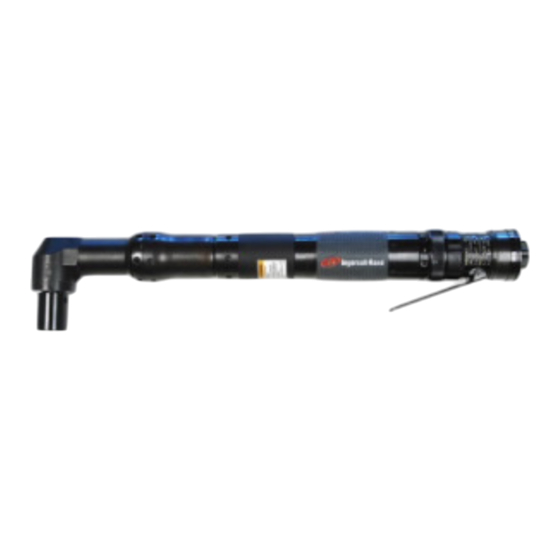
- Page 1 16572653 Edition 2 May 2014 Air Drill QA Series Maintenance Information Save These Instructions...
- Page 2 Product Safety Information WARNING Failure to observe the following warnings, and to avoid these potentially hazardous situations, could result in death or serious • injury. • Read and understand this and all other supplied manuals before installing, operating, repairing, maintaining, changing accessories on, or working near this product.
- Page 3 15. If the Muffler Elements (9) need to be cleaned or replaced, pull screw head. them out of the Back Cap. c) To restrict the rotation of the small angle head Spindle (63), 16. Grasp the flats at the inlet end of the Motor Housing in leather- thread a 1/4”-28 thread bolt into the Spindle or insert a rod into covered or copper-covered vise jaws, and using a 1-1/16”...
- Page 4 5. Invert the Gear Case on the table of an arbor press so that the NOTICE end face having the four notches makes contact with the table. Using a rod against the inner race of the Spindle Bearing, press The thread in the following step is a left-hand thread. Rotate the the Bearing from the Gear Case.
- Page 5 the Front End Plate on the bearing side of the End Plate, insert in the opening between the three Planet Gears. a 0.004” (0.1 mm) feeler gauge between the face of the rotor For Series QA27 and QA35, and models QA2119, QA2129, QA2139, body and the face of the End Plate at a point that is 180 degrees QA2159, QA1719, and QA1729, install the Planet Gear Head Drive away from where the pressure is applied.
- Page 6 (76) against the gear head. Needle Bearing inserting Tool Apply some grease to the annular groove on the shaft of the Spindle. Position the output end of the shaft inside the Lower Spindle Bearing Cap (79) with the leading edge of the shaft groove slightly below the end of the Cap.
- Page 7 with a flat end and no sharp edges, push the Seat to the bottom 19. Align the tab of the Motor Clamp Washer (33) with the internal of the opening until it seats flush. notch in the Housing and install it over the rotor hub and End Using needle nose pliers, insert the Throttle Valve (14), long stem Plate Alignment Pin against the Motor Seal.
- Page 8 ingersollrandproducts.com © 2014 Ingersoll Rand...
Need help?
Do you have a question about the QA Series and is the answer not in the manual?
Questions and answers