
Related Manuals for Ingersoll-Rand SUPER PAR-A-MATIC 8268-A Series


Summary of Contents for Ingersoll-Rand SUPER PAR-A-MATIC 8268-A Series
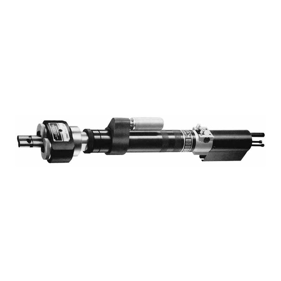
- Page 1 49999-308 Edition 2 March 2009 CCN: 04664280 SUPER PAR-A-MATIC® Self-Feed Drills With Dual Spindle Drilling Head Model 8268-A ( ) Operation and Maintenance Information Save These Instructions...
-
Page 2: Model Identification
Product Safety Information Intended Use: These Air Drills are designed for drilling, honing, reaming and hole sawing. For Additional information refer to Air Drills Product Safety Information Manual Form 04580353. Manuals can be downloaded from www.irtools.com. Model Identification 1-1/2” Stroke Model Number R.P.M. -
Page 3: Recommended Lubrication
DUAL SPINDLE ATTACHMENT can be lubricated thru either socket head set screw located on opposite sides of dual spindle housing. Where Used Ingersoll Rand Part # Description The felt type oil reservoirs contained in the housing should be Air Motor 29665 1 qt. -
Page 4: Manual Operation
Manual Operation The models 8268-A( ) are shipped from the factory with the MANUAL Each time the BUTTON BLEED VALVE marked “F” is depressed the BLEED VALVE (24130) installed in the “F” port at the rear of the Valve unit will start in the advancing (forward) mode. The unit will continue Housing. -
Page 5: Spindle Adjustment
Spindle Adjustment Centers Figure 3. Figure 1 To adjust the spindles as shown in figure 3 loosen both screws “A” and rotate both turrets in the direction indicated by the arrows to the For simple spindle adjustment the “X” “X” and “Y” “Y” axis of The approximate centers that are required. -
Page 6: Maintenance
(or assembling) parts which have a When ordering parts, be sure to list part number, part name, model number and serial number of tool. Use only genuine Ingersoll rand press fit. When removing or installing bearings, apply pressure to the bearing race that will be the press fit to the mating part;... - Page 7 Recommended Power Air Inlet System Model 23903-200 Connector 1/4” Female N.P.T.F Model 23103-300 Coupler 44908-( ), 3/8” i.d. Hose Assembly 3/8” Female N.P.T.F 3/8” N.P.T.F Male Fitting each end Model C28231-810 Filter-Regulator- Gauge-Lubricator Assembly Supply Model L26231-100 Standard Duty Lubricator-3/8” Ports Pressure Gauge 100067 Regulator Model R27231-100 Standard Duty 3/8”...
-
Page 8: Remote Operation
Shown below is the same system in schematic form. See Page 4 For Special Notes Supply Supply Ingersoll Rand Instant Tubing - 100 Ft. Rolls Model No. Color Size Model No. -
Page 9: Gearing Section
Disassembly and Assembly of Tools DISCONNECT AIR SUPPLY from tool or shut off air supply and exhaust Pipe Plug Y227-2-L (drain) line of compressed air BEFORE performing maintenance or service to tool. To minimize the possibility of parts damage and for convenience, the steps for disassembly or reassembly listed on the following pages are Trip Bracket recommended. -
Page 10: Adjustment Screw
Valve Adjustment screw Trip Pipe Housing Model Cover Bracket Nipple “A” “B” Assembly 8268-A ( )-1 40582-1 40292-2 40292-1 40857-6-2 40815 41713-3 8268-A ( )-3 40582 40292-3 40292-2 40857-7-2 Disassembly of Dual Spindle Section Assembly of Dual Spindle Section Pack bearings and coat gears with a good grade of bearing The Dual Spindle Attachment can be serviced without removing the Grease when assembling. - Page 11 46063 Dual Spindle Attachment Assembly Needle Roller 46029 Bearing 46038 Adapter 46060 Retaining Ring 46028 Driving spindle 46061 (Includes Needle Bearing) Dog Nut 45979 Retaining Ring 37285 Lock Ring 46027 “E” Ring Y180-31 Retaining Ring 46040 Body 46039 Driving Gear 46025 Nylon Washer 46032 (6) Needle Cage 46037 (4) Spindle 46062 (2) *...
- Page 12 47590 Washer 42271 Bearing (4) 46417 Gear (2) 40841 Shaft (2) (14 Teeth) 34490 Ring Gear 33706 Bearing Bearing 33703 40835 Spindle .9374 Least Clearance (See Note) 33697-1 Spacer 40842 Snap Ring 47589 Wave Washer (2) 46064 34574 Gear (7 int. - 15 ext. Teeth) Drive Gearing Assembly (4:1) NOTE: Bearing 33703 is Angular contact.
-
Page 13: Disassembly Of Motor
Bearing (4) 42271 40841 Shaft (2) 46416 Gear (2) 33708 Retaining Ring (18 Teeth) 33704 Bearing (2) 40840 Spindle .8124 40843 Snap Ring 40826 35270-ARO Ring Gear Auxiliary Gearing Assembly (7.43:1) Includes 35323 Grease Fitting Bearing (4) 42271 46417 Gear (2) 40841 Shaft (2) (14 Teeth) 33708 Retaining Ring... - Page 14 Disassembly of Air Piston Assemble Retaining Ring (Y147-212) into Sleeve, if removed. Assemble O-Rings (Y325-214) and (Y325-225) to Cap (40577) and Remove motor and Piston Section from tool as outlined on page 9. assemble Cap into Sleeve thru valve end. Apply a small amount of If the Air Cylinder has remained inside the Outer Sleeve, push the grease to Torque Pin to retain pin in place and assemble into Outer Piston Rod forward then pull it rearward to remove the Air Cylinder.
- Page 15 Disassembly of Valve Section Assembly of Valve Section NOTE: Whenever a part containing O-Rings has been removed from Spool Valve tool it is recommended that the O-Rings be replaced with new ones Remove two (2) caps (46697) with O-Rings (Y325-14). Spool Valve when reassembling part to tool.
-
Page 16: Drill Sizes
Optional Collets Part No. Bore Inch Accepts Part No. Bore Inch Accepts Dia. Drill Sizes Dia. Drill Sizes (Ref.) (Ref.) 46033-1 .079 46033-39 .228 7/32 46033-2 .083 46033-40 .232 5/64 46033-3 0.87 46033-41 .236 46033-4 .091 46033-42 .240 15/64 46033-5 .094 46033-43 .244... - Page 17 Accessories 41454 Foot Mount Assembly Collet type ±.005 4.000 (102 mm) ±.005 2.000 (51 mm) ±.010 21/64 thru counter bore .500 dia. (Approx.) 2.501 (64 mm) depth shown - (4) Holes ±.005 Foot Mount 41452 1-1/16 ±1/64 1.875 (48 mm) +.001 (27 mm) 3/4 (19 mm)
- Page 18 40589 Flange Mount Assembly ± 0.010 21/64 Dia. thru C’Bore 0.500 Dia. ± 0.005 Depth shown - (2) Holes 0.750 (19 mm) 5/16 (8 mm) Flange Mount 40586 1/2 (13 mm) ± 0.003 + 0.001 0.078 (2 mm) - 0.000 2.501 ±...
- Page 19 04664280_ed2...
-
Page 20: Dimensional Data
Dimensional Data 04664280_ed2... - Page 21 To Assemble to Tool: Remove Thread Guard (40581) from nose end of Outer Sleeve and CAUTION slip Manifold (43586-) with O-Rings (Y325-230)- over Outer Sleeve Do not over-tighten Set Screw (Y23-103) as it may cause and position over exhaust holes in sleeve. Outlet for muffler can distortion of the Outer Sleeve and thus cause damage to the be positioned either to the front or the rear as desired.
-
Page 22: Troubleshooting
Listed below are some of the most common causes for the self-feed drill to malfunction. Malfunctions beyond the scope of this manual should be brought to the attention of your Ingersoll Rand representative or return the tool to factory for repair. - Page 23 Notes:...
- Page 24 © 2009 Ingersoll Rand Company...
Need help?
Do you have a question about the SUPER PAR-A-MATIC 8268-A Series and is the answer not in the manual?
Questions and answers