
Related Manuals for FATEK FBs-1HLC


Summary of Contents for FATEK FBs-1HLC
- Page 1 FATEK FBs-1HLC Precision Load Cell Module Operation manual V1.1 06/07/2017 FATEK AUTOMATION CORP.
-
Page 2: Table Of Contents
Contents Chapter 1 1HLC module introduction ......................3 1.1 Module specification ..........................3 1.2 Module appearance and description ....................4 1.3 Application connections ........................4 1.4 Communication interface between 1HLC and PLC: ................ 6 1.5 1HLC application interface........................6 1.5.1 Application interface contents and Modbus comparison table ..............6 1.5.2 Detailed description ............................ -
Page 3: Chapter 1 1Hlc Module Introduction
Chapter 1 1HLC module introduction A load cell is formed by attaching a stress strain gauge to a metal elastic body. When the metal elastic body is subjected to pressure or tensile force, the deformation of the elastic body is detected and converted to an output voltage signal. -
Page 4: Module Appearance And Description
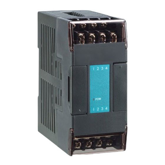
(CMXXE module can only use port 4) PORT4 PORT3 GRS: gross weight indicator MD: stable indicator NET GRS MD ZRO ZRO: zero-point indicator SIG: signal source Expansion flat FBs-1HLC cable connector EXC: Load cell excitation power supply (DC 5V 5%) 1.3 Application connections Four-line connection... - Page 5 Six-line connection Multiple-load-cell connection...
-
Page 6: Communication Interface Between 1Hlc And Plc
Modbus Protocol 0 I 2 3 4 5 6 7 FBs-24MCR2-AC AC100~240V FBs-1HLC Connect to PLC using Winproladder and change the PORT 3 communication parameters of Winproladder. The communication parameters of 1HLC are fixed as follow: PORT Connection speed Parity bit... -
Page 7: Detailed Description
Status/Settings register Address Name Settings Length 402305 AD internal value Word 402307 Display value 2Word SPAN calibration 402567 2Word weight 402561 Max. weight 2Word Calibration error 401793 Word message 402049 AD sampling frequency 0=100、1=50、2=25、3=12.5、4=6.25Hz Word 402052 Min. scale 1,2,5,10,20,50 Word 1.5.2 Detailed description Status/Control bit Address... -
Page 8: Chapter 2 Application Examples
Complete the hardware wiring connection first; please refer to the hardware equipment and connection scheme in below. Hardware: FBs-24MC*1, FBs-1HLC*1, and scale*1 1. Connect 1HLC cable to the left (communication) expansion port of PLC. 2. The 4 lines of the scale are connected to EXC+, EXC-, SIG+, and SIG- of 1HLC. -
Page 9: Ladder Diagram Programming
2.2 Setting PLC communication parameters Connect to PLC using Winproladder (24MC in this example) and change the PORT 3 communication parameters of Winproladder. The communication parameters of 1HLC are fixed as follow: PORT Connection Parity bit Data bit Stop bit format speed Port3... -
Page 10: 1Hlc Module Calibration
2.4 1HLC module calibration Module calibration allows the subsequently measured values to be more precise. The registers and connections in the calibration steps have already been converted by step 2 【Modbus Master Table】 in section 2.3 and the detailed corresponding registers are described in this section. 2.4.1 Zero-point calibration Confirm that the tray or tank scale is empty and execute zero-point calibration input (X0 from 0 to 1);...
Need help?
Do you have a question about the FBs-1HLC and is the answer not in the manual?
Questions and answers