Table of Contents
Advertisement
Available languages
Available languages
Quick Links
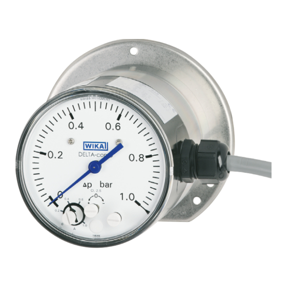
Differential pressure gauge with micro switches,
model DPGS40TA, with component testing
Differenzdruckmanometer mit Mikroschaltern,
Typ DPGS40TA, mit Bauteilprüfung
Differential pressure gauge with integrated working pressure indication
and up to two micro switches, model DPGS40TA
Operating instructions
Betriebsanleitung
DELTA-comb
EN
DE
Advertisement
Chapters
Table of Contents

Related Manuals for WIKA DELTA-comb DPGS40TA


Summary of Contents for WIKA DELTA-comb DPGS40TA
- Page 1 Operating instructions Betriebsanleitung Differential pressure gauge with micro switches, model DPGS40TA, with component testing Differenzdruckmanometer mit Mikroschaltern, Typ DPGS40TA, mit Bauteilprüfung DELTA-comb Differential pressure gauge with integrated working pressure indication and up to two micro switches, model DPGS40TA...
- Page 2 Page 3 - 30 Betriebsanleitung für Differenzdruckmanometer, Typ DPGS40TA Seite 31 - 57 © 08/2015 WIKA Alexander Wiegand SE & Co. KG All rights reserved. / Alle Rechte vorbehalten. WIKA is a registered trademark in various countries. ® WIKA ist eine geschützte Marke in verschiedenen Ländern.
-
Page 3: Table Of Contents
Disposal ......29 Annex 1: DNV GL approval Annex 2: SIL certificate Annex 3: VdTÜV certificate „Flow 100:2006“ Annex 4: Declaration of conformity Declarations of conformity can be found online at www.wika.com. WIKA operating instructions DPGS40TA with component testing... -
Page 4: General Information 4 En
Explanation of symbols WARNING! ... indicates a potentially dangerous situation that can result in serious injury or death, if not avoided. Information ... points out useful tips, recommendations and information for efficient and trouble-free operation. WIKA operating instructions DPGS40TA with component testing... -
Page 5: Safety
The instrument has been designed and built solely for the intended use described here, and may only be used accordingly. The manufacturer shall not be liable for claims of any type based on operation contrary to the intended use. WIKA operating instructions DPGS40TA with component testing... -
Page 6: Additional Instructions For Operation As A Flow Limiter In Accordance With Vdtüv Code Of Practice "Flow 100:2006
500 mm long. The requirements on the differential pressure lines in accordance with VdTÜV code of practice “Flow 100:2006” section 5.7.2.3 must be met. WIKA operating instructions DPGS40TA with component testing... -
Page 7: Functional Safety Of The Sil Version
IEC 61511 edition 1.0 Functional safety – Safety instrumented systems for the pro- cess industry ISO EN 13849-1:2008 Safety of machinery – Safety-related components of control systems – Part 1: General principles for design WIKA operating instructions DPGS40TA with component testing... - Page 8 The higher the safety integrity level of the safety-related system, the greater the probability that the safety function is executed. WIKA operating instructions DPGS40TA with component testing...
- Page 9 Number of cycles till 10 % of the components have failed dangerously Average number of operations per year β factor Factor for failure due to common causes, in terms of the interaction of several channels WIKA operating instructions DPGS40TA with component testing...
- Page 10 The safety function of the instrument is that, on falling differential pressure, the respective switch(es) will open. The changeover contacts should always be used so that the circuit opens on falling differential pressure (observe the closed-circuit principle). WIKA operating instructions DPGS40TA with component testing...
- Page 11 The instrument should be secured against the switch points being changed through the provided lead sealing of the setting elements. WARNING! The safety function must be checked by testing following any confi- guration procedure. WIKA operating instructions DPGS40TA with component testing...
- Page 12 V 495.01/15, see Annex 3 of these operating instructions. The safety-related parameters for the operation in safety integrated systems in accordance with ISO 13849 are to be taken from the certificate V 495.02/15, see Annex 3 of these operating instructions. WIKA operating instructions DPGS40TA with component testing...
-
Page 13: Personnel Qualification
Take sufficient precautionary measures. WARNING! The maximum surface temperature of the instrument may not exceed the ignition temperature of flammable media. Take sufficient precautionary measures. WIKA operating instructions DPGS40TA with component testing... -
Page 14: Product Label And Safety Marks
2nd digit: S = VdTÜV “Flow 100” 3rd digit: S = SIL version Date of manufacture Pin assignment Contact type Article number Maximal permissable pressure PS per European Pressure Equipment Directive WIKA operating instructions DPGS40TA with component testing... - Page 15 Risk of burns! Potentially dangerous situation caused by hot surfaces. Due to the maximum permissible process temperature of 90 °C, measuring cells, adapters, valves or other attachment parts can reach a temperature of 90 °C. WIKA operating instructions DPGS40TA with component testing...
-
Page 16: Specifications
1.4310 and separating diaphragm from FPM/FKM (option: NBR) Working pressure: Bourdon tube from Cu-alloy Transmission parts Stainless steel 1.4301, 1.4305, 1.4310, FPM/FKM (wetted) (option: NBR) Sealings (wetted) FPM/FKM (option: NBR) Movement Copper alloy WIKA operating instructions DPGS40TA with component testing... - Page 17 Cable gland M20 x 1.5 with 1 m free cable 1) I max. = 1.4 A for designs in accordance with VdTÜV code of practice "Flow 100" For further specifications see the corresponding product label, WIKA data sheet and order documentation.
-
Page 18: Design And Function
(7). The assistant scales (8) simplify the setting of the switch points. ⊖ ⊕ 4.2 Scope of delivery Cross-check scope of delivery with delivery note. WIKA operating instructions DPGS40TA with component testing... -
Page 19: Transport, Packaging And Storage
Hazardous environments, flammable atmospheres ■ WARNING! Before storing the instrument, any residual media must be remo- ved. This is of particular importance if the medium is hazardous to health, e.g. caustic, toxic, carcinogenic, radioactive, etc. WIKA operating instructions DPGS40TA with component testing... -
Page 20: Commissioning, Operation
The instruments should be protected against coarse dirt and wide fluctuations in ambient temperature. For sealing the connections, use flat gaskets, lens-type sealing rings or WIKA ■ profile sealings. In order to orientate the gauge so that the on-site display can be read as well as possible, a connection with clamp socket or union nut should be used. - Page 21 With gaseous substances, the temperature may increase as a result of compression warming. In these cases it may be necessary to throttle the rate of change of pressure or reduce the permissible medium temperature. WIKA operating instructions DPGS40TA with component testing...
- Page 22 (damp) densed Examples conden- boiling “liquid dry air moist air steam sate liquids gases” flue gases Pressure gauge above the tapping point Pressure gauge below the tapping point WIKA operating instructions DPGS40TA with component testing...
- Page 23 Dimensions in mm With aluminium measuring chamber Cable gland M20 x 1.5 with 1 m cable G1/4 20,5 With stainless steel measuring chamber Cable gland M20 x 1.5 with 1 m cable G1/4 20,5 WIKA operating instructions DPGS40TA with component testing...
-
Page 24: Electrical Connection
The mains connection lines to be provided must be dimensioned for maximum ■ instrument current supply and comply with IEC 227 or IEC 245. The instruments must be connected to the equipotential bonding of the plant. ■ For performance data see chapter 3 “Specifications” WIKA operating instructions DPGS40TA with component testing... - Page 25 For the safety circuit, which will switch off the heating if the steam generator falls below the minimum flow, only the normally open contact of the change-over contact should be connected (i.e. with Δp = 0 open circuit)! WIKA operating instructions DPGS40TA with component testing...
- Page 26 Seal the cable entry with the appropriate approved cable glands. ■ Cable socket design Only use cable with a diameter of 7 ... 13 mm M20 x 1.5 Install the connection cables securely. ■ WIKA operating instructions DPGS40TA with component testing...
-
Page 27: Commissioning
(with opened pressure compensating valve). Venting the measuring lines with liquid me- ■ dia and flushing of the measuring lines, in order to remove contamination. Shut-off valve Vent valve ⊖ side WIKA operating instructions DPGS40TA with component testing... -
Page 28: Panel Mounting Flange
1. Close the shut-off valve for the ⊕ and ⊖ media chamber 2. Open the vent valve 7.2 Panel mounting flange For aluminium measuring chamber For stainless steel measuring chamber Panel Panel WIKA operating instructions DPGS40TA with component testing... -
Page 29: Maintenance
9.3 Disposal Incorrect disposal can put the environment at risk. Dispose of instrument com- ponents and packaging materials in an environmentally compatible way and in accordance with the country-specific waste disposal regulations. WIKA operating instructions DPGS40TA with component testing... - Page 30 WIKA operating instructions DPGS40TA with component testing...
- Page 31 Entsorgung ..... . . 57 Anhang 1: Zulassung DNV GL Anhang 2: SIL-Zertifikat Anhang 3: VdTÜV-Bescheinigung „Strömung 100“ Anhang 4: Konformitätserklärung Konformitätserklärungen finden Sie online unter www.wika.de. WIKA Betriebsanleitung DPGS40TA mit Bauteilprüfung...
-
Page 32: Allgemeines
… weist auf eine möglicherweise gefährliche Situation hin, die zum Tod oder zu schweren Verletzungen führen kann, wenn sie nicht gemieden wird. Information … hebt nützliche Tipps und Empfehlungen sowie Informationen für einen effizienten und störungsfreien Betrieb hervor. WIKA Betriebsanleitung DPGS40TA mit Bauteilprüfung... -
Page 33: Sicherheit
Volumen: < 0,1 L ■ Das Gerät ist ausschließlich für den hier beschriebenen bestimmungsgemäßen Verwendungszweck konzipiert und konstruiert und darf nur dementsprechend verwendet werden. Ansprüche jeglicher Art aufgrund von nicht bestimmungsgemäßer Verwendung sind ausgeschlossen. WIKA Betriebsanleitung DPGS40TA mit Bauteilprüfung... -
Page 34: Zusatzhinweise Für Den Einsatz Als Strömungsbegrenzer Gemäß De Vdtüv Merkblatt „Strömung 100:2006
Blockventilen ist darauf zu achten, dass die Wirkdruckleitung zwischen Blockven- til und dem Wirkdruckaufnehmer als Bestandteil des Schaltgliedes mindestens 500 mm lang ist. Die Anforderungen an Wirkdruckleitungen gemäß VdTÜV Merkblatt „Strömung 100:2006“ Abschnitt 5.7.2.3 müssen eingehalten werden. WIKA Betriebsanleitung DPGS40TA mit Bauteilprüfung... -
Page 35: Funktionale Sicherheit Der Sil-Ausführung
Funktionale Sicherheit sicherheitsbezogener elektrischer/ele- ktronischer/programmierbarer elektronischer Systeme IEC 61511 Edition 1.0 Funktionale Sicherheit – Sicherheitstechnische Systeme für die Prozessindustrie ISO EN 13849-1:2008 Sicherheit von Maschinen – Sicherheitsbezogene Teile von Steuerungen – Teil 1: Allgemeine Gestaltungsleitsätze WIKA Betriebsanleitung DPGS40TA mit Bauteilprüfung... - Page 36 Integrity Level (SIL 1 bis SIL 4). Jeder Level entspricht einem Wahrscheinlichkeitsbereich mit welchem ein sicherheitsbezogenes System die festgelegten Sicherheitsfunktionen anforderungsgemäß ausführt. Je höher der Safety Integrity Level der sicherheitsbezogenen Systeme ist, umso größer die Wahrscheinlichkeit, dass die Sicherheitsfunktion ausgeführt wird. WIKA Betriebsanleitung DPGS40TA mit Bauteilprüfung...
- Page 37 Mittlere Zeit bis zum Auftreten eines gefahrbringenden Ausfalls Anzahl von Zyklen, bis 10 % der Komponenten gefährlich ausgefallen sind Mittlere Anzahl der jährlichen Betätigungen β-Faktor Faktor für den Ausfall infolge gemeinsamer Ursachen, im Hinblick auf das Zusammenwirken mehrerer Kanäle WIKA Betriebsanleitung DPGS40TA mit Bauteilprüfung...
- Page 38 Die Sicherheitsfunktion des Gerätes besteht darin, dass bei sinkendem Diffe- renzdruck der bzw. die Schalter geöffnet werden. Die Wechsler sind in einer Sicherheitsfunktion immer so zu verwenden, dass der Stromkreis bei sinkendem Differenzdruck geöffnet wird (Ruhestromprinzip beachten). WIKA Betriebsanleitung DPGS40TA mit Bauteilprüfung...
- Page 39 Die Kennzeichnung muss z.B. durch einen geeigneten Aufkleber aktualisiert wer- den. Das Gerät sollte gegen Änderung der Schaltpunkte durch die vorgesehene Verplombung der Einstellelemente gesichert werden. WARNUNG! Die Sicherheitsfunktion muss nach einem Konfigurationsvorgang durch einen Test überprüft werden. WIKA Betriebsanleitung DPGS40TA mit Bauteilprüfung...
- Page 40 Systemen nach IEC 61508 und IEC 61511 sind dem Zertifikat V 495.01/15 zu entnehmen, siehe Anlage 3 dieser Betriebsanleitung. Die sicherheitstechnischen Kenngrößen für den Einsatz in sicherheitsgerichteten Systemen nach ISO 13849 sind dem Zertifikat V 495.02/15 zu entnehmen, siehe Anlage 3 dieser Betriebsanleitung. WIKA Betriebsanleitung DPGS40TA mit Bauteilprüfung...
-
Page 41: Personalqualifikation
Vorschriften beachtet werden. WARNUNG! Messstoffreste in ausgebauten Messgeräten können zur Gefähr- dung von Personen, Umwelt und Einrichtung führen. Ausreichende Vorsichtsmaßnahmen ergreifen. WARNUNG! Die maximale Oberflächentemperatur des Gerätes darf die Zündtemperatur brennbarer Messstoffe nicht überschreiten. Ausreichende Vorsichtsmaßnahmen ergreifen. WIKA Betriebsanleitung DPGS40TA mit Bauteilprüfung... -
Page 42: Typenschild Und Sicherheitskennzeichnungen
Code 1. Stelle E = Einfach-Mikroschalter 850.3 D = Zweifach-Mikroschalter 850.3.3 2. Stelle S = VdTüV „Strömung 100“ 3. Stelle S = SIL-Ausführung Herstellungsdatum Anschlussbelegung Kontakttyp Artikelnummer Maximal zulässiger Druck PS nach europäischer Druckgeräterichtlinie WIKA Betriebsanleitung DPGS40TA mit Bauteilprüfung... - Page 43 Vor Montage und Inbetriebnahme des Gerätes unbedingt die Betriebsanleitung lesen! Verbrennungsgefahr! Möglicherweise gefährliche Situation durch heiße Oberflächen. Aufgrund der maximal zulässigen Prozesstemperatur von 90 °C können Messzellen, Anschlussstücke, Ventile oder sonstige Anbauteile eine Temperatur von 90 °C erreichen. WIKA Betriebsanleitung DPGS40TA mit Bauteilprüfung...
-
Page 44: Technische Daten
Achsabstand 26 mm Messglieder Differenzdruck: Druckfedern aus CrNi-Stahl 1.4310 und (messstoffberührt) Trennmembrane aus FPM/FKM (Option: NBR) Betriebsdruck: Rohrfeder aus Cu-Legierung Übertragungsteile CrNi-Stahl 1.4301, 1.4305, 1.4310, FPM/FKM (messstoffberührt) (Option: NBR) Dichtungen FPM/FKM (Option: NBR) (messstoffberührt) Kupferlegierung Zeigerwerk WIKA Betriebsanleitung DPGS40TA mit Bauteilprüfung... - Page 45 Elektrischer Anschluss Kabelverschraubung M20 x 1,5 mit 1 m freiem Kabel 1) I max. = 1,4 A für Ausführung nach VdTÜV Merkblatt „Strömung 100“ Weitere technische Daten siehe jeweiliges Typenschild, WIKA-Datenblatt und Bestellunterlagen. Für Typen mit optionalem Explosionsschutz „Zusatzinformation für explosionsgefährdete Bereiche (Ex i), Typen DPS40, DPGS40, DPGS40TA und...
-
Page 46: Aufbau Und Funktion
Stützflächen (6) erreicht. Die Schaltpunktverstellung erfolgt über die frontseitig zugänglichen Einstells- chrauben (7). Die Hilfsskalen (8) erleichtern die Schaltpunkteinstellung. ⊖ ⊕ 4.2 Lieferumfang Lieferumfang mit dem Lieferschein abgleichen. WIKA Betriebsanleitung DPGS40TA mit Bauteilprüfung... -
Page 47: Transport, Verpackung Und Lagerung
Explosionsgefährdete Umgebung, entzündliche Atmosphären ■ WARNUNG! Vor der Einlagerung des Gerätes müssen alle ggf. anhaftenden Messstoffreste entfernt werden. Dies ist besonders wichtig, wenn das Medium gesundheitsgefährdend ist, wie z. B. ätzend, giftig, krebserregend, radioaktiv, usw. WIKA Betriebsanleitung DPGS40TA mit Bauteilprüfung... -
Page 48: Inbetriebnahme, Betrieb
Zur Abdichtung der Anschlüsse sind Flachdichtungen, Dichtlinsen oder ■ WIKA-Profildichtungen einzusetzen. Um das Gerät in die Stellung zu bringen, in der sich die örtliche Anzeige am besten ablesen lässt, ist ein Anschluss mit Spannmuffe oder Überwurfmutter zu empfehlen. Beim Ein- und Ausschrauben dürfen die Geräte nicht am Gehäuse angezogen werden, sondern nur an den... - Page 49 Geräten selbst abhängig, sondern hauptsächlich von der jeweiligen Messstofftemperatur! Bei gasförmigen Stoffen kann sich die Temperatur durch Kompressionswärme erhöhen. In solchen Fällen muss ggf. die Druckänderungsgeschwindigkeit gedrosselt bzw. die zulässige Messstofftemperatur reduziert wer- den. WIKA Betriebsanleitung DPGS40TA mit Bauteilprüfung...
- Page 50 Teil vollständig Messleitung ausga- dig ver- förmig kondensiert konden- send dampft (feucht) siert Beispiele Kondensat siedende „Flüssig- trockene feuchte Luft Wasserdampf Flüssigkei- gase“ Luft Rauchgase Manometer oberhalb des Entnahme- stutzens Manometer unterhalb des Entnah- mestutzens WIKA Betriebsanleitung DPGS40TA mit Bauteilprüfung...
- Page 51 6. Inbetriebnahme, Betrieb Abmessungen in mm Mit Aluminium-Messkammer Kabelverschraubung M20 x 1,5 mit 1 m Kabel G1/4 20,5 Mit CrNi-Stahl-Messkammer Kabelverschraubung M20 x 1,5 mit 1 m Kabel G1/4 20,5 WIKA Betriebsanleitung DPGS40TA mit Bauteilprüfung...
-
Page 52: Elektrischer Anschluss
Die vorgesehenen Netzanschlussleitungen müssen für die größte Stromaufna- ■ hme des Gerätes bemessen sein und IEC 227 oder IEC 245 entsprechen. Die Geräte sind in den Potenzialausgleich der Anlage mit einzubeziehen. ■ Leistungsdaten siehe Kapitel 3 „Technische Daten“ WIKA Betriebsanleitung DPGS40TA mit Bauteilprüfung... - Page 53 2. Kontakt 1. Kontakt Kabelanschlussdose Für den Sicherheitsstromkreis, der bei Unterschreiten des Min- destdurchflusses die Beheizung des Dampferzeugers abschalten soll, darf nur der Schließer des Umschaltkontaktes angeschlossen werden (d.h. der bei Δp = 0 offene Kreis)! WIKA Betriebsanleitung DPGS40TA mit Bauteilprüfung...
- Page 54 Anschlussleitungen müssen für den Umgebungstemperaturbereich der ■ Applikation geeignet sein. Kabeleinführung mit den entsprechend zugelassenen Kabelverschraubungen ■ dicht verschließen. Ausführung der Kabeldose Nur Kabel mit Durchmesser 7 ... 13 mm verwenden M20 x 1.5 Anschlusskabel fest verlegen. ■ WIKA Betriebsanleitung DPGS40TA mit Bauteilprüfung...
-
Page 55: Inbetriebnahme
Prozess sowie Vermeidung einseitiger Überdruckbelastung während der Anfahr- bzw. Betriebsphase (bei geöffnetem Druckausgleichsventil). Entlüftung der Messleitungen bei flüssigen ■ Messstoffen und Spülung der Messleitun- Absperrventil Entlüftungs- ⊖ ventil -Seite gen, um Verunreinigungen zu entfernen. WIKA Betriebsanleitung DPGS40TA mit Bauteilprüfung... -
Page 56: Befestigungsrand Für Schalttafelmontage
2. Absperrventil der ⊕- und ⊖-Messstoffraum schließen Arbeitsgangfolge zur Demontage des Messgerätes bei laufenden Prozess ■ 1. Absperrventil der ⊕- und ⊖-Messstoffraum schließen 2. Entlüftungsventil öffnen 7.2 Befestigungsrand für Schalttafelmontage Für Aluminium-Messkammer Für CrNi-Stahl-Messkammer Schalttafel Schalttafel WIKA Betriebsanleitung DPGS40TA mit Bauteilprüfung... -
Page 57: Wartung
Ausgebautes Messgerät vor der Rücksendung spülen bzw. säubern, um Mitarbeiter und Umwelt vor Gefährdung durch anhaftende Messstoffreste zu schützen. 9.3 Entsorgung Durch falsche Entsorgung können Gefahren für die Umwelt entstehen. Gerätekomponenten und Verpackungsmaterialien entsprechend den landesspezifischen Abfallbehandlungs- und Entsorgungsvorschriften umweltgerecht entsorgen. WIKA Betriebsanleitung DPGS40TA mit Bauteilprüfung... -
Page 58: Annex 1: Dnv Gl Approval
That the Pressure Gauge with type designation(s) DPGS40TA Issued to WIKA Alexander Wiegand SE & Co. KG Klingenberg a. Main, Bayern, Germany is found to comply with DNV GL rules for classification – Ships Pt.4 Ch.6 Piping systems Application :... - Page 59 (+/- 90 days) and after 3.5 years (+/- 90 days) to verify that the conditions for the Type Approval are complied with. Refer to the Class Programme DNVGL-CP-0338, Sec.4. Form code: TA 251 Revision: 2016-12 www.dnvgl.com Page 2 of 2 WIKA operating instructions DPGS40TA with component testing...
-
Page 60: Annex 2: Sil Certificate
Annex 2: SIL certificate WIKA operating instructions DPGS40TA with component testing... - Page 61 Annex 2: SIL certificate WIKA operating instructions DPGS40TA with component testing...
-
Page 62: Annex 3: Vdtüv Certificate „Flow 100:2006
Annex 3: VdTÜV certificate “Flow 100” WIKA operating instructions DPGS40TA with component testing... -
Page 63: Annex 4: Declaration Of Conformity
Annex 4: Declaration of conformity WIKA operating instructions DPGS40TA with component testing... - Page 64 Annex 4: Declaration of conformity WIKA operating instructions DPGS40TA with component testing...
- Page 65 WIKA operating instructions DPGS40TA with component testing...
- Page 66 WIKA operating instructions DPGS40TA with component testing...
- Page 67 WIKA operating instructions DPGS40TA with component testing...
- Page 68 WIKA subsidiaries worldwide can be found online at www.wika.com. WIKA-Niederlassungen weltweit finden Sie online unter www.wika.de. WIKA Alexander Wiegand SE & Co. KG Alexander-Wiegand-Straße 30 63911 Klingenberg • Germany Tel. +49 9372 132-0 Fax +49 9372 132-406 info@wika.de www.wika.de WIKA operating instructions DPGS40TA with component testing...
Need help?
Do you have a question about the DELTA-comb DPGS40TA and is the answer not in the manual?
Questions and answers