
Related Manuals for WIKA Mensor CPA8001


Summary of Contents for WIKA Mensor CPA8001
- Page 1 Operating Instructions Air Data Test Set CPA8001 Air Data Test Set CPA8001 PN 0018608001G • 05/2019...
- Page 2 Air Data Test Set CPA8001 This Warning symbol indicates that danger of injury for persons and the environment and/or considerable material damage (mortal danger, danger of injury) will occur if the respective safety precautions are not taken. This Caution symbol indicates danger for the system and material if the respective safety precautions are not taken.
-
Page 3: Table Of Contents
Air Data Test Set CPA8001 Table of Contents 1. General Information 1.1 Warranty 1.2 Important Notice 1.3 FCC Radio Frequency Emission Notice 1.4 Trademarks and Copyrights 1.5 Software License Agreement 1.6 Mensor Service Plus 1.6.1 After the Warranty 1.6.2 Calibration Services 1.6.3 Accreditations 1.7 Packaging for Shipment 2. - Page 4 Air Data Test Set CPA8001 5.3 Dimensions (inches) 5.4 Turning on the CPA8001 5.5 Pressure Connections 5.6 Pneumatic Connections and Pressure Fittings 5.7 Electrical & Communication Connections 5.7.1 Notices Regarding the Electrical Connections 5.7.1.1 Power Supply 5.7.1.2 Interfaces 5.7.1.3 Ethernet Interface 5.7.1.4 USB Host Interface 5.7.1.5 USB Device Interface 5.7.1.6 RS-232 Interface...
- Page 5 Air Data Test Set CPA8001 6.2.13.4 State of the Isolation Valves when the CPA8001 is off 6.2.14 Vacuum Setting 6.2.15 Automated Zero 7. Setup 7.1 General Tab 7.1.1 Instrument Mode 7.1.2 Linked Modes 7.1.3 Language 7.1.4 Brightness 7.1.5 Volume 7.1.6 Zero Reminder Interval 7.1.7 Save [Configuration] 7.1.8 Load [Configuration] 7.2 Remote Tab 7.2.1 Remote Command Set 7.2.2 IEEE-488 Address 7.2.3 Ethernet Communication...
- Page 6 Air Data Test Set CPA8001 7.4.2.1 Calibration Environment 7.4.2.2 Calibration Pressure Standards 7.4.2.3 Calibration Media 7.4.2.4 Calibration Setup 7.4.3 Calibration Procedures 7.4.3.1 1 Point Calibration 7.4.3.2 2 Point Calibration 7.4.3.3 Linearize 7.4.3.4 Head Correction (password protected) 7.4.4 Programs 7.4.5 Favorites 7.4.6 Troubleshoot 7.4.7 Admin 7.5 Info Tab...
-
Page 7: General Information
Air Data Test Set CPA8001 General Information Warranty All products manufactured by Mensor LP (Mensor) are warranted to be free of defects in workmanship and materials for a period of two years from the date of shipment. No other express warranty is given, and no affirmation of Seller, by words or actions, shall constitute a warranty. SELLER DISCLAIMS ANY IMPLIED WARRANTIES OF MERCHANTABILITY OR FITNESS FOR ANY PARTICULAR PURPOSES WHATSOEVER. -
Page 8: Trademarks And Copyrights
CPA8001 Trademarks and Copyrights WIKA is a registered trademark of WIKA Alexander Wiegand SE & Co. KG. Mensor is a registered trademark of Mensor LP. ©2012, Mensor LP. All rights reserved. All other brand and product names are trademarks or registered trademarks of their respec- tive companies. -
Page 9: Calibration Services
Air Data Test Set CPA8001 1.6.2 Calibration Services In addition to servicing our own products, Mensor provides complete pressure calibration services up to 20,000 psi for many pressure instruments. This service includes a Certificate of Compliance and Calibration and a record of traceability to the pressure standards of the United States National Institute of Standards and Technology (NIST). -
Page 10: Safety Notices
Air Data Test Set CPA8001 Safety Notices User Responsibilities To ensure safety, the operator must make sure that the following conditions are met: ■ The system is used properly, no dangerous media are used and that all technical specifications are observed. ■ The system is in perfect operating condition. ■ The operation manual is legible and accessible to the user at the system’s location. ■ The system is operated, serviced and repaired only by authorized and qualified personnel. ■ The user receives instruction on industrial safety and environmental protection, and is knowledgeable of all operating instructions and safety notices relevant to the current procedure. -
Page 11: Warnings And Caution Notices
Air Data Test Set CPA8001 Warnings and Caution Notices WARNING: HIGH PRESSURE! High pressure gases are potentially hazardous. Energy stored in these gases can be released suddenly and with extreme force. High pressure systems should be assembled and operated only by personnel who have been trained in proper safety practices. -
Page 12: Product Description
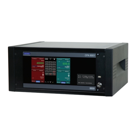
Air Data Test Set CPA8001 Product Description General Description The CPA8001 Air Data Test Set has the following features: ■ 19” rack mount compatibility ■ Designed for serviceability and reliability ■ Wide screen display with glass capacitive touchscreen ■ Front panel door gives access to instrument interior ■ Ps/Pt or Ps/Qc transducer package (Appendix 11.1 gives an overview of altitude and airspeed avionics terminology and hardware.) ■... -
Page 13: Front Panel
Air Data Test Set CPA8001 Front Panel The front of the CPA8001 has a smooth, uncluttered appearance. Its main feature is the large color display plus an identification label in the lower right corner of the display panel. The display panel is hinged for easy access to remove or replace the transducer modules inside. The instructions for access- ing the transducers are provided in Section 10.2.2, Transducer removal/replacement. -
Page 14: Main Screen Features
Air Data Test Set CPA8001 3.3.5 Main Screen Features On power up, the main screen will show a numeric data entry key pad in the center of the display, Ps channel on the left and Qc or Pt channel on the right. The data entry key pad can be switched between 4 different methods for data entry. See Section 6, Local Operation, for more details. Appendix 11.1 gives an overview of altitude and airspeed avionics terminology and hardware and includes definitions of Ps, Pt and Qc. -
Page 15: Main Features
Air Data Test Set CPA8001 Buttons on the screen are shown with a gradient background. When inactive the buttons are shown with the gradient dark on the bottom and light on the top; when selected the button changes color and is light on the bottom and dark on the top. -
Page 16: Specifications
Air Data Test Set CPA8001 Specifications Measure Specifications Transducer Range Uncertainty Specification 0 ... 29.5 to 0 ... 37 (0 ... 950 to 0 ... 1253), in HgA @ 0 C (mbar) Measurement Uncertainty 0.009% IS-50 0 ... 40 to 0 ... 110 (0 ... 1355 to 0 ... 3725), in HgA @ 0 C (mbar) Measurement Uncertainty 0.01% IS-50... -
Page 17: Control Specifications
Air Data Test Set CPA8001 Control Specifications Stability of controlled pressure 0.002 % Pressure Span Altitude Altitude Stability Airspeed Airspeed (ft.) (+/- ft.) (knots) Stability (+/- Knots) -1870 0.56 4.684 0.59 1.042 5000 0.69 0.540 10000 0.80 0.363 20000 1.11 0.273 30000 1.58 0.218 40000 2.39 0.182 50000 3.88... -
Page 18: Transducer Removal/Replacement
Air Data Test Set CPA8001 Operating temperature 15 to 35 °C Storage temperature 0 to 70 °C Humidity 0 to 95% RH non-condensing Certifications CE-mark Conformity certificate Includes calibration certificate(s). The Mensor calibration laboratory is ac- credited in accordance with the recognized International Standard ISO/IEC Calibration 17025:2005 and also meets the requirements of ANSI/NCSL Z540-1-1994. Ac- creditation is by the American Association for Laboratory Accreditation (A2LA). WARNING! This is class A equipment for emissions and is intended for use in industrial environments. -
Page 19: Regulator
Air Data Test Set CPA8001 Regulator The CPA8001 is supplied with a needle valve regulator (NVR) that is tuned for the transducer module that is installed. A transducer module with an identical range can be interchanged with the transducer module installed. If there is a need to replace the transducer module with one of a different range consult the factory. -
Page 20: Intelliscale
Air Data Test Set CPA8001 IntelliScale IntelliScale (IS) is a “short hand” way to describe a percent of reading uncertainty specification. Or, said another way, IntelliScale is designed to further reduce the uncertainty specification. It does this by split- ting the full span in two. It then defines the uncertainty of the lower portion of the span as a percent of full scale, and the uncertainty of the upper portion as a percent of reading. For the CPA8001 the IntelliScale specification is 0.009% IS-50. This means that the lower half of the range (50% of the maximum range) has an uncertainty of 0.009% x 50% or 0.0045% of the maximum range. The upper half (values > 50% of the maximum range) has an uncertainty of 0.009% of the pressure reading. Thus, any pressure within the lower portion of the pressure range has a fixed number for the uncertainty (0.0045% of Maximum Range), while the uncertainty anywhere in the upper portion of the span is a sliding scale number that is a percent (0.009%) of any reading. For example, a device with a pressure range from 0 to 32 in HgA with an IntelliScale uncertainty speci- fication of 0.009% IS-50 will have an uncertainty of 0.0014 in Hg (0.009% x 50% x 32) on any pressure from 0 psi to 16 in HgA, and an uncertainty of 0.009% of reading (0.009% x R) for any pressure above 16 in HgA (See figure 4.6) -
Page 21: Installation
Air Data Test Set CPA8001 Installation WARNING: READ THESE INSTRUCTIONS BEFORE INSTALLATION! The installation location must meet the following conditions (see also Section 4, Specifications): ■ Ambient temperature: Compensated temperature range 15° to 45° C ■ Humidity: 0-95% relative humidity, non-condensing ■ Flat, horizontal location; secure fixed working surface (desk top model) or proper installation in a sturdy 19” mounting rack or cabinet ■... -
Page 22: Dimensions (Inches)
Air Data Test Set CPA8001 Dimensions (inches) esk top 16.2 19.5 16.2 19.5 front view side view 16.9 ack mount 16.9 front view side view Adaptor Fitting: 1/4 in. Tube OD x 7/16-20 Male SAE/MS Straight Thread 6 mm Tube OD x 7/16-20 Male SAE/MS Straight Thread AN4 x 7/16-20 Male SAE/MS Straight Thread or AN6 x 7/16-20 Male SAE/MS Straight Thread rear view... -
Page 23: Turning On The Cpa8001
Air Data Test Set CPA8001 Turning on the CPA8001 After the pressure connections are secure in accordance with Section 5.5 below, apply power to the power connector on the rear of the instrument and switch the power switch ON. The instrument will go through an initialization process and system check. - Page 24 Air Data Test Set CPA8001 ■ Pt/Qc or Ps Supply The pressure supplied to the pressure connection labeled “Supply” on either channel should be approximately 10% higher than the full scale of the pressure transducer installed in that channel. Most CPA8001’s are supplied with an internal connection between the Pt/Qc Supply port and the Ps Supply port. In this case, the Ps supply port will be plugged and it is only necessary to connect a supply pressure to the Pt/Qc port that is 10% higher than the highest pressure in either channel.
-
Page 25: Pneumatic Connections And Pressure Fittings
Air Data Test Set CPA8001 5.6 Pneumatic Connections and Pressure Fittings The CPA8001 is supplied with 1/4 in. tube OD x 7/16-20 male SAE/MS straight thread adaptors or 6 mm tube OD x 7/16-20 male SAE/MS straight thread adaptors (per order). The 7/16-20 male SAE/MS straight thread end of the adaptors should be connected to the instrument’s 7/16-20 female SAE/MS straight thread connections. -
Page 26: Electrical & Communication Connections
Air Data Test Set CPA8001 Electrical & Communication Connections WARNING! The electrical installation must be done according to the following instructions while observing the relevant regulations. It is to be performed by individuals familiar with the safety regulations for working on electrical connec- tions. -
Page 27: Notices Regarding The Electrical Connections
The USB Device jack is a standard USB Type B receptacle interface used for remote communication. The USB Driver can be downloaded at http://www.mensor.com/download_software_instrument_en_ um.WIKA?ActiveID=31350 5.7.1.6 RS-232 Interface The RS-232 interface is a 9-pin D-Sub socket used for remote communication. -
Page 28: Local Operation
Air Data Test Set CPA8001 Local Operation 6.1 General This section describes the procedures for operating the CPA8001 from the front panel. Instructions for operating the instrument from an external computer are covered in Section 8, Remote Operation. System configuration setup parameters are explained in Section 7, Setup. -
Page 29: Buttons, Keys, Switches, Tabs, And Other Terms
Air Data Test Set CPA8001 6.1.1 Buttons, Keys, Switches, Tabs, and Other Terms Many of the words and symbols displayed on screen are active touch points, such that when touched or pressed something will change if it is an allowable action. In this manual these touch sensitive points are shown inside brackets such as [Setpoint], the button seen in the upper right corner of each section where a setpoint can be entered (See figure 6.1.2). These touch points may be referred to as a button, a key (such as a number key), a toggle switch, a radio button or a tab. -
Page 30: Main Screen Buttons / Features
Air Data Test Set CPA8001 6.2 Main Screen Buttons / Features The table below is a reference list of the main screen buttons and their purpose and reference to sections in this manual that explain them in detail: Table 6.2 - Reference List of the Main Screen Features Button/ Indication Feature... -
Page 31: Cpa8001 Air Data Test Set Configuration Options: Ps/Pt Or Ps/Qc
Air Data Test Set CPA8001 6.2.1 CPA8001 Air Data Test Set Configuration Options: Ps/Pt or Ps/Qc A Ps/Pt ADTS has an absolute pressure Ps channel and an absolute pressure Pt channel. In this unit Ps and Ps rate are displayed on the left side of the main screen and Pt and Pt Rate or an emulated Qc and Qc rate can be displayed on the right side. A Ps/Qc ADTS has an absolute pressure Ps channel and a differential pressure Qc channel. In this unit Ps and Ps Rate are displayed on the left side of the main screen and Qc and Qc rate or an emulated Pt and Pt rate can be displayed on the right side. 6.2.2 Avionics / Pressure Reading The large, green numbers displayed in figure 6.2.2 below are the Altitude and Airspeed reading of the transducer connected to the respective Measure/Control ports. -
Page 32: Setpoint Buttons
Air Data Test Set CPA8001 6.2.3 Setpoint Buttons Pressing any [Setpoint] button will activate the keypad (or other entry method) to accept a new setpoint value for altitude, altitude rate, airspeed or airspeed rate. The [Setpoint] button will turn yellow indicat- ing that it is ready to accept a value. The current setpoint value is displayed in the window just below the [Setpoint] button on the main screen (see figure 6.2.4a). The setpoint value can also be adjusted incre- mentally by use of one of four setpoint entry methods: ■... -
Page 33: Setup
Air Data Test Set CPA8001 Figure 6.2.4b - Pending Setpoints 6.2.5 Setup Press Setup [ ] to move out of the main screen and into the setup screens. Notice the bottom row of tabs and the arrow on the left end of the row (See figure 6.2.5). Each tab will bring up a screen relevant to the subject in the tab title. Touching the arrow will revert to the main operating screen. Figure 6.2.5 - Setup Screen Tabs From the main screen, the last visited setup screen will return if Setup [ ] is pressed again. Opera- tional information for the setup screens is contained in Section 7,... -
Page 34: Number Pad
Air Data Test Set CPA8001 6.2.6.1 Number Pad The [Number Pad] button provides 10 digits for numeric entry, plus the decimal point and a sign key. This keypad becomes active when a setpoint button is touched. The sign key [+/-] will toggle between positive and negative values and can be activated at any time during the string entry. After a [Setpoint] button is selected, each key stroke on the key pad will echo within the selected (yellow background) setpoint window. -
Page 35: Number Pad / Step
Air Data Test Set CPA8001 6.2.6.2 Number Pad / Step The “Number Pad Step” key pad functions in two different ways: (1) A setpoint can be entered in the same way as the Number Key Pad above: key in the number and press Enter [ ], that number is then immedi- ately accepted into the setpoint value. (2) Key in a number and press the Step Up [ ] or the Step Down [ key, (without pressing the Enter [ ] key), that number will be used to... -
Page 36: Program Data Entry
Air Data Test Set CPA8001 setpoint being changed. 6.2.6.4 Program Data Entry The Program Data entry method provides an automated way to interact with the CPA8001. Most settings or processes that can be entered manually can be programmed into the unit and saved and used in the Program portion of the data entry screen. -
Page 37: Favorites
Air Data Test Set CPA8001 6.2.7 Favorites The Favorites [ ] button provides a place to store programs that are frequently used and also contains several prepackaged programs that are used to perform a leak test and a single point zero of each transducer. Programs that are displayed in the Favorites menu are chosen in the Setup [ ] / Applications / Favorites screen. -
Page 38: Secondary Display
Air Data Test Set CPA8001 6.2.9 Secondary Display There is an extra line available in the lower portion of each parameter screen reserved for the operator to (optionally) display the equivalent pressure or air data values in Metric, English or Avionics units (see figure 6.2.9a). The choices are available for selection in the Setup [ ] / [Ps, Pt or Qc] / [Secondary Display]. The Units displayed can be chosen in Setup [... -
Page 39: Limits
Air Data Test Set CPA8001 6.2.10 Limits Limits are shown in four places in the main screen. Each parameter set ( Ps/Ps Rate, Qc/Qc Rate or Pt/ Pt Rate) can have limits imposed by the operator. Limits and the relative pressure values within those limits are shown for Ps and Qc or Pt using a dynamic bar graph. Limits are shown numerically below the bar graph for the Ps and Qc or Pt parameters and at the bottom of the Ps Rate and Qc Rate or Pt Rate parameter windows. The limits are entered in the Setup [ ] / [Ps, Qc or Pt] [Maximum Limits]/ [Minimum Limits] screen (see Section 7.3.8). -
Page 40: Instrument Modes / Avionics Units / Pressure Units
Air Data Test Set CPA8001 6.2.11 Instrument Modes / Avionics Units / Pressure Units There are three different instrument modes for the CPA8001 Air DataTest Set: “Ps/Qc Air Data”, “Ps/Pt Pressure”, and “Ps/Qc Pressure”. The Mode is selected in Setup [ ] / [General] / [Instrument Mode]. Ps/Qc Air Data Mode uses Feet or Meters for altitude, and Knots, MPH, km/hr, m/s or Mach for airspeed. Both Ps/Pt Pressure and Ps/Qc Pressure modes use a variety of English or Metric pressure units plus two user defined units. The denominator for the rate unit for each channel can be Seconds [Sec] or Minutes [Min]. The Rate Unit is selected in Setup [ ] / [Ps, Pt, or Qc] / [Rate Units]. The numerator of the rate unit will always be identical to the associated unit selected for that parameter’s channel. The unit chosen is displayed directly under the current reading for each parameter on the main screen, just above the bar graph and the numerical limits. -
Page 41: Operating Modes
Air Data Test Set CPA8001 6.2.13 Operating Modes Each channel of the CPA8001 has threes operating modes: Measure, Control, and Vent. When the system is turned on and the channels are initalized, both channels will automatically be placed in Vent Mode.The operator can switch from one mode to another by using the mode selection keys located just below each channel on the front panel display. -
Page 42: Measure Mode
Air Data Test Set CPA8001 6.2.13.1 Measure Mode In Measure mode, the instrument measures the pressure at the transducer connected to the Measure/ Control port. The Measure mode is activated by pressing the [Measure] button. Measure Mode Figure 6.2.13.1a - Measure Mode If the pressure is beyond the permissible measurement range, the pressure reading is displayed in red instead of white figures. As soon as a pressure of approximately 110% of the full scale nominal range is reached, an integrated safety relief valve opens and releases the pressure into the inside of the instru- ment. - Page 43 Air Data Test Set CPA8001 The figure below shows the state of the isolation valves in Measure mode. BAROMETRIC REFERENCE Ps REGULATOR Zero Ref. XDU volume Reference Connection Qc Only volume Pt/Qc REGULATOR 6.2.13.1b - Isolation Valves in Measure Mode Operating Instructions - CPA8001...
-
Page 44: Control Mode
Air Data Test Set CPA8001 6.2.13.2 Control Mode In Control mode, the instrument provides a precise pressure, altitude or airspeed output at the Measure / Control Port. The indication of the current value will turn green when the setpoint has been reached and the stable window settings have been satisfied. - Page 45 Air Data Test Set CPA8001 The figure below shows the state of the isolation valves in Control mode. The regulator is active in Control. BAROMETRIC REFERENCE Ps REGULATOR Zero Ref. XDU volume Reference Connection Qc Only volume Pt/Qc REGULATOR Figure 6.2.13.2b - Isolation Valves in Control Mode Operating Instructions - CPA8001...
-
Page 46: Vent Mode
Air Data Test Set CPA8001 6.2.13.3 Vent Mode Vent mode vents act as a safe “Go-To-Ground” function. Pressing the Vent button will activate a controlled vent to relieve the pressure in the system and in the device connected to the measure control port. The pressure will be controlled through the regulator toward atmospheric pressure (zero altitude) at an opera- tor defined vent rate and then, at 1 mbar from atmospheric pressure, will vent through a solenoid valve and a 0.0079 inch diameter orifice. The Default values for the vent rate is 5000 ft/min. The operator can... - Page 47 Air Data Test Set CPA8001 Figure 6.2.13.3b shows the state of the isolation valves in Vent mode. BAROMETRIC REFERENCE Ps REGULATOR Zero Ref. XDU volume Reference Connection Qc Only volume Pt/Qc REGULATOR Figure 6.2.13.3b - Illustration Showing Isolation Valves in Vent Mode Operating Instructions - CPA8001...
-
Page 48: State Of The Isolation Valves When The Cpa8001 Is Off
Air Data Test Set CPA8001 6.2.13.4 State of the Isolation Valves when the CPA8001 is off When the CPA8001 is turned off the valves revert to their normal state: either Normally Open (NO) or Normally Closed (NC) and the regulator becomes inactive, as indicated below. BAROMETRIC REFERENCE Ps REGULATOR Zero Ref. XDU volume Reference Connection Qc Only volume Pt/Qc REGULATOR Figure 6.2.13.4 - Power Off Operating Instructions - CPA8001... -
Page 49: Vacuum Setting
Air Data Test Set CPA8001 6.2.14 Vacuum Setting The CPA8001 requires a stable vacuum for accurate measurements and for zeroing the Ps and Pt trans- ducers. This is achieved by running a pre-programmed zero bleed sequence. The zero bleed sequence can be accessed by pressing the Setup [ ] button in the main screen and then clicking “Zero Bleed”... -
Page 50: Automated Zero
Air Data Test Set CPA8001 Note the stable vacuum reading, this reading needs to be within 400 - 700 mtorr for accurate zero calibra- tion of the Ps and Pt transducers. When the vacuum reading is outside the 400 - 700 mtorr tolerance, the vacuum level inside the CPA8001 is adjusted by the vacuum bleed valve on the rear panel of the instru- ment (Figure 6.2.14c). - Page 51 Air Data Test Set CPA8001 A second screen (below) will appear where the zeroing sequence can be initiated by pressing the check button [ ]. Figure 6.2.15b - Initiate/Cancel Zero Process Pressing the check button will start a sequence that will progress as follows: 1. If a Ps/Qc transducer is installed, the sequence will start by zeroing the Qc transducer at atmospheric pressure then it will zero the Ps transducer as described in steps 2-5. If there is a Ps/Pt transducer installed, the process will start at step 2.
-
Page 52: Setup
Air Data Test Set CPA8001 Setup After the instrument has been powered on and the main screen is displayed, press the Setup [ button to setup parameters or make changes to the instrument settings. Setup [ ] button Figure 7a - Location of the Setup [ ] button on the main screen The following is a menu tree that shows the general layout of the setup menus. -
Page 53: General Tab
Air Data Test Set CPA8001 General Tab 7.1.1 Instrument Mode The Instrument Mode is accessed by pressing Setup [ ] / [General] / [Instrument Mode]. The instru- ment mode has three settings: [Ps/Qc Air Data], [Ps/Pt Pressure] and [Ps/Qc Pressure]. These modes are slightly different depending on what type of transducer module is physically installed in the instrument. For a CPA8001 with a Ps/Qc transducer module installed, the Ps/Qc Air Data mode and the Ps/Qc Pressure mode will use the output readings directly from the Ps and Qc transducers for all functions. In this configuration the Pt reading in the Ps/Pt Pressure mode will be a calculated (emulated) value derived from the equation Pt = Ps + Qc. On the other hand, if a Ps/Pt transducer module is installed, the Ps/Pt Pressure mode will use the output readings directly from the Ps and Pt transducers for all functions. In this configuration the Qc readings in the Ps/Qc Air Data mode and the Ps/Qc Pressure mode will be a calculated (emulated) value derived from the same equation Pt = Ps + Qc, or algebraically reordered Qc = Pt - Ps. -
Page 54: Linked Modes
Air Data Test Set CPA8001 7.1.2 Linked Modes The Linked Mode is accessed by pressing Setup [ ] / [General] / [Linked Modes]. Linked Modes has two settings: [on] and [off]. The [on] selection turns on a functional link between channels with respect to the Control Modes: Measure, Control and Vent. When the [on] is selected the linked icon [ ] will appear in the main screen and selection of the Measure, Control or Vent Control mode in one channel will change the other channel to the same mode. If [off] is selected the Control Mode of each channel is independent of the other; selecting a Control Mode in one channel will not effect the mode of the other channel. -
Page 55: Brightness
Air Data Test Set CPA8001 7.1.4 Brightness The selection for screen brightness is accessed by pressing Setup [ ] / [General] / [Brightness]. This menu provides a place to set the global brightness of the instrument’s screens. When the [Brightness] button is chosen a graduated brightness “bar graph” will appear on the side. This is a sliding scale of brightness and can be changed by sliding ones finger up and down on the bar graph or simply touching an area on the graph that corresponds to a brightness level. -
Page 56: Zero Reminder Interval
Air Data Test Set CPA8001 7.1.6 Zero Reminder Interval By pressing Setup [ ] / [General] / [Zero Reminder Interval], an interval can be set that serves as a reminder that it is time to perform the automated zero on the internal Ps and Pt or Qc transducers. After the interval elapses, the zero indicator and actuation key [ ] on the main screen turns orange as a reminder to perform the automated zero function. The interval can be set to a number of days from 1 to 365. -
Page 57: Load [Configuration]
Air Data Test Set CPA8001 7.1.8 Load [Configuration] To load a preset configuration, access Setup [ ] / [General] / [Load]. The CPA8001 can store a complete set of parameters and settings, see section 7.1.7 Save [Configuration] above. Each Configuration can be recalled (loaded) as needed. The [Load] button within the [General] tab of the Setup ] menu, shown in Figure 7.1.8, provides a place to choose the predefined configurations for the instrument. When the [Load] button is chosen a choice of several configurations are displayed on the sidebar. When one configuration is chosen its settings will be applied to the instrument. Figure 7.1.8 - Load [Configuration] Operating Instructions - CPA8001... -
Page 58: Remote Tab
Air Data Test Set CPA8001 Remote Tab Within the [Remote] tab of the Setup [ ] menu are parameters used to configure the communications to and from the CPA8001. The command set being used, and the settings for IEEE-488, Ethernet, and Serial communications are in these menus. This menu has two pages that can be accessed by pressing the up or down [ ] page button. -
Page 59: Ethernet Communication
The termination character of the remote response (transmit termination) may be changed to one of the following: CRLF Carriage return and line feed Carriage return Line feed End of input None No termination Default Set to the default termination character for the active command set. Defaults: CRLF SCPI WIKA = LF 6610 = CRLF Operating Instructions - CPA8001... -
Page 60: Serial Communications
Air Data Test Set CPA8001 Figure 7.2.4 Termination Character 7.2.5 Serial Communications Serial Communication parameters are set on the second page of the Setup [ ] / [Remote] Menu. Settings for the Serial parameters: Baud Rate, Data Bits, Stop Bits, Parity and Echo are available here. When a parameter button is pressed a choice selector will be presented on the right side and an appro- priate selection can be entered for the respective parameter. -
Page 61: Channel Setup [Ps], [Pt] And [Qc]
Air Data Test Set CPA8001 Channel Setup [Ps], [Pt] and [Qc] Channel setup screens for Ps, Pt and Qc are identical except for four additional parameter in the Qc Channel which are “Negative Qc Limit”, “Qc Reference”, “True Airspeed Enable” and “True Airspeed Temperature” (explained in Section 7.3.7) and the Pt channel cannot be configured with Air Data units, only pressure units. Channel Setup Screens are accessed through the Setup [ ] / [Ps], [Pt] or [Qc] menus. There are two pages in each of the menus, one labelled “Channel” and the other labelled “Limit”. Figure 7.3a shows the “Channel”... -
Page 62: Setup Units
Air Data Test Set CPA8001 7.3.1 Setup Units The pressure or avionics unit is set within the Setup [ ] / [Ps], [Pt] or [Qc] menu using the [Units] button. There are three choices for Ps and Qc and two choices for Pt on the right side of this menu: [English], [Metric] for the Pt channel and [English], [Metric] or [Avionics] units for the [Ps] and [Qc] channel. The units chosen are displayed as the primary unit for each channel and in the numerator of the associated rate. -
Page 63: Secondary Display
Air Data Test Set CPA8001 7.3.3 Secondary Display The Secondary Display is used to set an additional, alternative display showing a unit that is different from the primary display unit. The Secondary Display is set using the Setup [ ] / [Ps], [Pt] or [Qc] / [Secondary Display] button. Choices are [None], [Pressure] or [Altitude] for Ps & Qc and [None] or [Pressure] for Pt. Choosing [None] turns off the secondary display. See Section 6.2.9 for main screen location of the secondary display. Figure 7.3.3 - Ps Secondary Display set to [Pressure] 7.3.4 Secondary Display Units As with the main display Units, the Secondary Display Units have the same choices accessed through the Setup [... -
Page 64: Filter
Air Data Test Set CPA8001 7.3.5 Filter Selections to change the transducer reading display filter is found in the Setup [ ] / [Ps], [Pt] or [Qc] [Filter] menu. The filter can be set to Off, Low, Normal or High. The transducer filter acts on the output pressure indicated on the instrument, filtering out small pneumatic and electrical variations in the pressure transducer output. This is done by mathematically smoothing the output reading using a low pass filter on the output of the pressure transducer. Figure 7.3.5 shows the Qc filter set to “Normal”. Figure 7.3.5 - Filter, [Qc] / [Filter] / [Normal] 7.3.6 Resolution The Resolution setting is accessed in the Setup [ ] / [Ps], [Pt] or [Qc] / [Resolution] menu. The current resolution setting is shown with a blue background. Selecting [4], [5] or [6] from the right side selection menu will set the display reading resolution to 4 digits, 5 digits or 6 digits respectively. -
Page 65: Negative Qc Limits
Air Data Test Set CPA8001 7.3.7 Negative Qc Limits The Negative Qc Limits setting is only applicable to the Qc Channel. It is a setting designed to protect external transducers or indicators that may be damaged by an excessive negative Qc Pressure. Accord- ing to the equation, Qc = Pt - Ps, a negative Qc will result if the Ps is greater than the Pt. Set the Negative Qc Limit to a value that will not harm external components. If this limit is reached, then a valve will open between the Ps and Pt channels to equalize the pressure. The units for the Negative Qc Limit will be the unit chosen for the Qc Channel, except while in Mach units, in which case pressure units will be used. While in other airspeed units with TAS (true airspeed) enabled, the value will be set relative to sea level. Figure 7.3.7 - Negative Qc Limits Operating Instructions - CPA8001... -
Page 66: Qc Reference
Air Data Test Set CPA8001 7.3.8 Qc Reference The Qc Reference controls the internal pneumatic connection to the reference side (low pressure side) of the Qc transducer. This setting is accessed in the Setup [ ] / [Qc] / [Qc Reference] menu. Setting to [Ps] will pneumatically connect the Qc Reference to the Ps transducer. Setting to [Rear Panel] will pneumatically connect the Qc reference to the rear panel port. Choosing rear panel isolates the Qc channel from the Ps channel. This is useful when calibrating an airspeed indicator at current atmospheric pressure or when calibrating the Qc transducer. Figure 7.3.8 - QC Reference Operating Instructions - CPA8001... -
Page 67: True Airspeed Enable
Air Data Test Set CPA8001 7.3.9 True Airspeed Enable In order to display True Airspeed instead of Indicated Airspeed the True Airspeed setting must be turned [On] by accessing the Setup [ ] / [Qc] / [True Airspeed Enable] screen. True Airspeed is a calculated value that adjusts for the air density around the aircraft. True airspeed is an indication of the speed of the aircraft relative to the air mass in which it is flying.True Airspeed can only be enabled while in “Ps/Qc Air Data”... -
Page 68: Maximum Limits And Minimum Limits
Air Data Test Set CPA8001 7.3.11 Maximum Limits and Minimum Limits The second page of the Setup [ ] / [Ps], [Pt] or [Qc] menu can be accessed by touching the Down Arrow [ ] on the first page. The first button on the “Limits” page of the setup screen is [Maximum Limit], the second is [Minimum Limit]. The [Maximum Limit] and [Minimum Limit] buttons accessed under the Setup [ ] / [Ps], [Pt] or [Qc] / Page Down [ ] screen provides a place to limit the setpoints that can be chosen in the main screen. These limits can only be set within the range of the channel’s transducer. The minimum limit must be lower than the maximum limit. -
Page 69: Stable Limits And Stable Delay
Air Data Test Set CPA8001 Figure 7.3.11b - Minimum Limits (Ps Altitude Channel) 7.3.12 Stable Limits and Stable Delay The [Stable Limits] and [Stable Delay] parameters set the limits that must be satisfied for the controller channel to display a stable condition. The [Stable Limits] setting defines a +/- numeric window (in the current units of measure), centered at the setpoint. The [Stable Delay] setting defines a time duration. A stable condition exists when the pressure sensed by the channel’s transducer is within the stable window for a time duration equal to the stable delay. A stable condition is indicated when the pressure, altitude or airspeed reading turns green. - Page 70 Air Data Test Set CPA8001 Figure 7.3.12c illustrates how the Stable Limits and Stable Delay parameters work in practice. 3000 Stable Limits 2500 Stable Delay 2000 1500 Altitude indication is white Altitude indication is green 1000 Time Figure 7.3.12c - Illustration of Stable Limit and Stable Delay Operating Instructions - CPA8001...
-
Page 71: Rate Maximum Limits And Rate Minimum Limits
Air Data Test Set CPA8001 7.3.13 Rate Maximum Limits and Rate Minimum Limits The [Rate Maximum Limit] and [Rate Minimum Limit] buttons accessed under the Setup [ ] / [Ps], [Pt] or [Qc] / Page Down [ ] screen provides a place to limit the rate setpoint that can be chosen within a channel. The [Rate Minimum Limit] can be set at or above a predetermined point for each channel. Above this minimum value the controller can achieve its specified rate stability while ramping up to a control setpoint if external volumes and vacuum pump specifications conform to those specifies in Section 4 - Specifica- tions. The [Rate Maximum Limit] also has a predetermined rate above which it cannot be set, but high rates are also limited by the capacity of the external vacuum pump, the external volume attached to the measure control port and the altitude setpoint among others. The controller can, therefore, be set to a rate that it will never be able to achieve. -
Page 72: Rate Stable Limits And Rate Stable Delay
Air Data Test Set CPA8001 7.3.14 Rate Stable Limits and Rate Stable Delay The [Rate Stable Limits] and [Rate Stable Delay] parameters set the limits that must be satisfied for the rate in each channel to display a stable condition. The [Rate Stable Limits] setting defines a +/- percent of reading rate window, centered at the rate setpoint. The [Rate Stable Delay] setting defines a time duration. A stable rate condition exists when the rate of change sensed by the channel’s trans- ducer is within the Rate Stable Limits window for a time duration equal to the Rate Stable Delay. A stable condition is indicated when the pressure rate, altitude rate or airspeed rate reading turns green. A stable indication is typically displayed in control mode while controlling to a setpoint. -
Page 73: Vent Rate (Go-To-Ground Parameters)
Air Data Test Set CPA8001 7.3.15 Vent Rate (Go-To-Ground parameters) The CPA8001 Air Data Test Set has a built in Go-To-Ground feature. Each channel will always vent at a controlled [Vent Rate] through the internal regulator to protect connected devices that may be sensitive to rapid changes in pressure. The [Vent Rate] for the Ps, Pt or Qc channels can be set with the Setup [ / [Ps], [Pt] or [Qc] / [Vent Rate] button. At 1 mbar from ambient atmospheric pressure the unit will switch from the controlled vent to a direct vent out through a solenoid valve and a 0.0079 inch diameter orifice. Figure 7.3.15 shows the [Vent Rate] screen for the Ps channel. -
Page 74: Applications
Air Data Test Set CPA8001 Applications Press the [Applications] tab in the Setup [ ] screen and a screen will appear containing various labelled icons that when pressed access other screens that provide the following functions: ■ Calibration of internal transducers ■ Sequence program configuration ■ Selection of favorites viewable in the local operation screen ■ A troubleshooting screen that displays errors and remote command and response echoing ■... -
Page 75: Passwords
Air Data Test Set CPA8001 7.4.1 Passwords All the Calibration screens ([1 Point Calibration] [2 Point Calibration] [Linearize] and [Head Correction]) are password protected with the “calibrate password”. The “service password” allows access to the Service screens ([Tune Ps], [Tune Qc/Pt], [Admin] and [Software]). Figure 7.4.1 shows the [Applications] screen when unlocked by both the calibration and service passwords. The Default Passwords sent with the instrument are as follows: Calibration Password: 123456 Admin Password: 987654 Both passwords can be changed and saved in the [Admin] page within the... -
Page 76: Calibration - Guidelines
Air Data Test Set CPA8001 7.4.2 Calibration - Guidelines The top row of labelled icons in the [Applications] screen are the password protected applications for calibration of the CPA8001 Transducer Module. Calibration can be performed by the owner of the instru- ment or sent back to Mensor for a ISO-17025, A2LA accredited calibration. NOTICE: During the first re-calibration at the Mensor factory a service file is started in which every calibration and all extra services are recorded. This section is included for those who wish to calibrate their CPA8001 within their own calibration lab. -
Page 77: Calibration Setup
Air Data Test Set CPA8001 7.4.2.4 Calibration Setup Refer to the calibration setup illustration on the following page (See Figure 7.4.2.4 - Calibration Setup). The illustration shows a typical calibration setup for absolute and gauge pressure instruments. The ‘Pressure Standard’ is normally a deadweight tester, a precision piston balance or a precision manometer. -
Page 78: Calibration Procedures
Air Data Test Set CPA8001 Ps selected. 7.4.3 Calibration Procedures All calibration screens can be accessed in the Setup [ ] / [Applications] area. To access the these screens a password must be entered, See Section 7.4.1 for the default password. There are three methods used to calibrate transducers in the CPA8001 transducer module. A simple [1 Point Calibration] can be used to adjust a single point (usually the zero point). A [2 Point Calibration] extends this capabil- ity to adjust two points (usually points close to the Zero and Span). The [Linearize] calibration provides a way to calibrate and linearize the pressure curve using from 1 to 11 points over the range of each transducer. -
Page 79: Point Calibration
Air Data Test Set CPA8001 7.4.3.1 1 Point Calibration The 1 Point Calibration screen provides a place to calibrate an internal transducer, the vacuum refer- ence transducer or the optional barometer using a single pressure point. This is usually done to adjust the zero range of a transducer. The transducer being calibrated is chosen by pressing the [Ps], [Pt], [Qc], [Vacuum] or [Barometer] tab at the bottom of the screen (see figure 7.4.3.1a below). The transducer currently chosen for calibration will have a blue gradient background. - Page 80 Air Data Test Set CPA8001 Complete the steps below to complete a 1 Point calibration of a Ps, Pt or Barometric transducer. 1. S elect [Ps], [Pt] or (optional) [Barometer] from the button of the 1 Point Calibration Screen. See figure 7.4.3.1b below. 2. Press the [Measure] button. 3. Connect a high accuracy reference standard capable of measuring absolute pressure to the Measure/ Control port of the transducer channel being calibrated or, in the case of the Barometer, connect to the barometer barb fitting on the back of the instrument.
- Page 81 Air Data Test Set CPA8001 Complete the steps below to complete a 1 Point calibration of vacuum transducer. 1. R un the “Zero Bleed Sequence” from the [Home]/[Favorites] tab as explained in section 6.2.14, Vacuum Setting. 2. Connect a high accuracy transducer to the back of the instrument on the small vacuum reference transducer port (this may require installing a barb fitting).
-
Page 82: Point Calibration
Air Data Test Set CPA8001 7.4.3.2 2 Point Calibration A 2 Point Calibration adjusts both the offset and the slope of the active transducer. This is accomplished by interacting with the “2 Point Calibration” screen (See figure 7.4.3.2). Figure 7.4.3.2 - 2 Point Calibration Complete the steps below for a complete 2 Point Calibration: 1. S elect [Ps], [Pt], [Qc] or (optional) [Barometer] from the button of the 2 Point Calibration Screen. See figure 7.4.3.2. 2. To calibrate the “Low Point”: • The Measure /Control port of the transducer’s channel should be supplied with a suitable, “low point”... -
Page 83: Linearize
Air Data Test Set CPA8001 • Supply a pressure to the Measure/Control Port using a pressure standard. This pressure should be as close as possible to the full scale value of the selected transducer or at least within 20% of that value. The [Too Low] button will change to a [Reading] button when the pressure reaches an acceptable range. • After the pressure stabilizes, select the [Reading] button to accept the instrument’s reading of the pressure input. The actual reading will appear within a green background where the [Reading] button was. • Press the [New Value] button and, via the numeric key pad, enter the reference pressure obtained from the calibration standard. This value is obtained from the pressure measured by the calibration standard. - Page 84 Air Data Test Set CPA8001 Linearization can also be accomplished for each transducer in a “live Calibration” by pressing the [Linearize] / [Live Cal] button (See figure 7.4.3.3b). The Live Cal allows the calibration technician to perform the calibration and linearization for each transducer in a more direct way. In the Live Cal, the reference standard is connected to the transducer channel’s Measure/Control port and the CPA8001 channel is placed in Measure mode. Choose the transducer to be linearized by pressing the [Ps], [Qc], [Pt], or [Barometer] button. The reference pressure generated by the standard is recorded in the “Reference”...
-
Page 85: Head Correction (Password Protected)
Air Data Test Set CPA8001 7.4.3.4 Head Correction (password protected) The Setup [ ] / [Applications] / [Head Correction] screen is the place to enter parameters that affect the offset that occurs when a device is being calibrated and located at a different level (elevation) compared to the transducer inside of the CPA8001. Touching any of the active buttons in this screen will activate the number key pad. Each of the four rows in figure 7.4.3.4 represent a different parameter in the head correction calculation. In the [Height (INST-DUT)] row, the level of the Device Under Test (DUT) should be subtracted from the CPA8001 reference point (INST) and entered. The gas density used within the calibration system, the gas temperature, and the local gravity should be entered in the subse- quent fields. The default height is zero (0) indicating that there is no head correction applied. [English] or [Metric] units can be chosen be pressing the related button. -
Page 86: Programs
Air Data Test Set CPA8001 7.4.4 Programs The Setup [ ] / [Applications] / [Programs] screen is used to create, view and edit programs that are used to automatically run a sequence of commands within the CPA8001. There are two tabs at the bottom of the Program screen shown in figure 7.4.4a. The Display tab provides a place to view each program. Pressing the program label (program selection button) at the top left will allow selection of alter- native programs from the side bar. -
Page 87: Favorites
Air Data Test Set CPA8001 7.4.5 Favorites The Setup [ ] / [Applications] / [Favorites] screen is used to select programs that will appear in the main screen when the Favorites [ ] icon is pressed. The current list of favorites is shown in figure 7.4.5 on the left. Press one of these and then press the available programs on the right to update the current favorites list with that program. Figure 7.4.5 - Favorites 7.4.6 Troubleshoot The Setup [... -
Page 88: Admin
Air Data Test Set CPA8001 7.4.7 Admin The Setup [ ] [Applications] [Admin] Screen has a place to change the Calibration and Service passwords. Press the [Change Password...Calibrate] button to enter a new password, and then accept by pressing the Check [. .] button. The same procedure applies to the [Change Password ...Service] button. Figure 7.4.7 - Change Password Info Tab After the instrument has been powered on and the main screen is displayed press the Setup [ ] key and then press the [Info] tab. Information displayed will be the Mensor contact address information, the instrument’s serial number, firmware version and a list of the integrated transducers and other informa-... -
Page 89: Remote Operation
There are various command sets available in the CPA8001, including the Mensor command set, SCPI WIKA command set, and the Ruska 6610 command set. The recommended command set for new development is the Mensor command set. All commands must be terminated with a <CR> and/or a <LF>. - Page 90 Air Data Test Set CPA8001 Table 8.2 - Remote Command Set Command/Query Data Function/Response See table below Returns data per the current output format Acquire? 15 char string. This command is used when multiple computers would like to control the instru- ment.
- Page 91 Air Data Test Set CPA8001 AUXQC? <sp>n.nnnnne+nn<cr><lf> Returns the secondary display reading of channel QC AUXR? <sp>n.nnnnne+nn<cr><lf> Returns the secondary display rate reading of the active channel AUXAR? <sp>n.nnnnne+nn<cr><lf> Returns the secondary display rate reading of channel A AUXBR? <sp>n.nnnnne+nn<cr><lf> Returns the secondary display rate reading of channel B AUXPSR? <sp>n.nnnnne+nn<cr><lf>...
- Page 92 Air Data Test Set CPA8001 Crate? <sp>CCCC<cr><lf> Returns the control rate – CCCC is variable in length and corresponds to the param- eters for the CRATE command Ctype? Returns the type of regulator for the active channel Decpt? <sp>n<cr><lf> Returns the number of decimal points for the active channel.
- Page 93 Air Data Test Set CPA8001 Listcal? <sp>PRI,{sn},{td},{mmddyy}; Returns the calibration dates of the installed {BAR,{sn},{td},{mmddyy}}<cr transducer for the active channel. Channel ><lf> A (Ps) will respond with barometer informa- tion when present. Listrange? <sp>PRI,1,min,max,2,min,ma Returns the ranges of the installed trans- x;{BAR,1,min,max} ducers for the active channel Localgravity...
- Page 94 Air Data Test Set CPA8001 Ptype? <sp>CCCCC<cr><lf> Returns “Absolute” or “Gauge” for the pressure type RangeMax? <sp>XXXXXXX<cr><lf> Returns the maximum range of the active transducer and turndown in the current units RangeMin? <sp>XXXXXXX<cr><lf> Returns the minimum range of the active transducer and turndown in the current units Rate? <sp>XXXXXXX<cr><lf>...
- Page 95 Air Data Test Set CPA8001 Sensor C, X Sets the active transducer where C = Primary and X = Turndown. Note: All ADTS channel only have a Primary sensor, and all sensors only have 1 turndown, so this command is trivial. Sensor? <sp>C,X<cr><lf> Returns active transducer as above Sensorid? <sp>0 ID MENSOR, Returns the active sensor’s Identification ADTS_XDC, SSSSSSSS, string, including the address, manufac- Vx.xx<cr><lf>...
- Page 96 Air Data Test Set CPA8001 Step Value inside upper and lower Sets the control step size for the instrument limits and inside the range of the active transducer and turndown. Step- Optional value Jogs the setpoint down one step Step+ Optional value Jogs the setpoint up one step Step?
-
Page 97: Scpi Commands
Air Data Test Set CPA8001 SCPI Commands Table 8.3 - SCPI Commands Command Function MEASure [:PRESsure] [R]? Returns the reading from range R in current engineering units. :TEMPerature[R]? Returns the temperature from range R :RATE[R]? Returns the pressure rate/sec from range R :BAROmetric? Returns the barometric pressure :SLEW? - Page 98 Air Data Test Set CPA8001 :MEDium? Returns medium SYSTem :DATE <i,i,i> Sets the system date YYYY,MM,DD :DATE? Returns system date YYYY,MM,DD :TIME <i,i,i> Sets the system time HH,MM,SS :TIME? Returns system time HH,MM,SS :ERRor[:NEXT]? Return error code, description :KLOCk ON/OFF/1/0 Lock or unlock keyboard :PRESet Load known values :SAVe no function (not needed) :VERSion? Return SCPI version 1994.0.
- Page 99 Air Data Test Set CPA8001 Index Unit mbar kp/cm² lbf/ft² cmH2O(4°C) inH2O(4°C) inH2O(20°C) inH2O(60°F) ftH2O(4°C) mmHg(0°C) cmHg(4°C) inHg(0°C) inHg(60°F) user user user OUTPut :STATe ON/OFF/1/0 ON or 1 = control OFF or 0 = measure :STATe? Returns 0 for measure 1 for control :MODE MEASure/CONTrol/VENT Sets the operation mode :MODE? Returns the mode string :STABle? Returns 1 if stable 0 if not :AUTOvent ON/OFF/1/0...
- Page 100 Air Data Test Set CPA8001 [:AMPLitude]? Returns the setpoint :SLEW <n> Sets the slew rate setpoint :SLEW? Returns the slew rate setpoint :TOLerance <n> Sets the stable window :TOLerance? Returns the stable window CALCulate :LIMit :LOWer<n> Sets minimum control limit :LOWer? Returns minimum control limit :UPPer<n>...
-
Page 101: Scpi Error Messages And Error Codes
Air Data Test Set CPA8001 SCPI Error Messages and Error Codes A recognized command is displayed at the device in the headline with “Remote...”. In case of error “Remote error...” is displayed. A maximum of 100 errors are stored and can be retrieved successfully. Table 8.4 - Error Messages and Error Codes Code Error String Returned... -
Page 102: Options
Air Data Test Set CPA8001 Options This section lists options available for the CPA8001. Users might consider letting the factory install a special feature not listed here. Mensor welcomes the opportunity to quote on such requests. The cost of adding an enhancement frequently will amortize itself in a very short time because of improved process efficiency. -
Page 103: Adaptor Fittings
Air Data Test Set CPA8001 barometric reading can be used to calculate QNH -“barometric pressure adjusted to sea level.” Adaptor Fittings ■ 1/4 in. Tube OD x 7/16-20 Male SAE/MS Straight Thread ■ 6 mm Tube OD x 7/16-20 Male SAE/MS Straight Thread ■ AN4 x 7/16-20 Male SAE/MS Straight Thread or AN6 x 7/16-20 Male SAE/MS Straight Thread Maintenance The CPA8001 was designed for maintenance-free operation. - Page 104 Air Data Test Set CPA8001 Table 10.2 - Troubleshooting Type Problem Correction Action The system has been switched on and no Switch the system off. Wait 5 seconds and measurement(s) have appeared and the switch the system on. entire area of the screen is white (or dark). The screen is dark and the corrective action Check that the power cable is connected for #1 above has no effect...
-
Page 105: Pressure Transducer Location
Air Data Test Set CPA8001 10.2.1 Pressure Transducer Location Ps/Pt or Ps/Qc Transducer Barometer Vacuum Reference Transducer Figure 10.2.1 - Top View 10.2.2 Transducer Removal / Replacement Figure 10.2.2 - Front View, Panel Open The front panel is hinged to allow access to the self-contained pressure transducer. To open the front panel, first turn off system power, then loosen the captive screws near the right hand edge of the panel. - Page 106 Air Data Test Set CPA8001 CAUTION: Further access to the interior of the instrument is NOT recommended. There are no user-serviceable plumbing or parts inside. In addition to the danger- ous voltages present (line voltage), there are circuits sensitive to electrostatic discharge damage.
-
Page 107: Appendix
It has a nonlinear inverse relationship to altitude. As altitude increases, static pressure decreases. This relationship has been defined in the “US Standard Atmosphere”. The equations used in the Mensor CPA8001 are based on this document. Ps-Rate: Ps-Rate is the Static Pressure rate of change. -
Page 108: Measurement Units
Air Data Test Set CPA8001 11.2 Measurement Units The Units command selects the measurement units to be output on the bus and the display. Table 11.2 - Measurement Units Description Output format millibar mbar hectopascals kilopascals kilogram per centimeter squared kg/sq cm inches of mercury @0 degrees Celcius inHg @0C... -
Page 109: Conversion Factors, Bar
Air Data Test Set CPA8001 kilogram per meters squared kg/m pascals megapascals dynes per centimeter squared dyn/cm percent full scale % FS User 1 User 1 User 2 User 2 11.3 Conversion Factors, bar The following table lists factors which should be used as multipliers when converting other pressure units to or from bar. -
Page 110: Conversion Factors, Psi
Air Data Test Set CPA8001 11.4 Conversion Factors, PSI The following table lists factors which should be used as multipliers when converting other pressure units to or from psi. Table 11.4 - Conversion Factors, psi Pressure unit To convert from PSI To convert to PSI 0.06894757 14.50377... -
Page 111: Conversion Factors, Millitorr
Air Data Test Set CPA8001 kg/m 6894.757 0.0001450377 0.006894757 145.0377 dyn/cm 68947.57 0.00001450377 % FS (PSI / RANGE) x 100 (% FS x RANGE) / 100 USER 1 USER 2 11.5 Conversion Factors, millitorr The following table lists factors which should be used as multipliers when converting other pressure units to or from millitorr. - Page 112 Table 11.5 - Conversion Factors, millitorr Code Pressure unit To convert from millitorr To convert to millitorr 0.00001933672 51715.08 inHg @0C 0.00003936995 25400.08909 inHg @60F 0.00003948117 25328.53093 inH2O @4C 0.0005352534 1868.273977 inH2O @20C 0.0005362028 1864.966281 inH2O @60F 0.0005357739 1866.458778 ftH2O @4C 0.00004460451 22419.25773 ftH2O @20C 0.00004468356 22379.59744 ftH2O @60F 0.00004464783 22397.50637...
- Page 113 Operating Instructions - CPA8001 PN 0018608001G • 05/2019...
- Page 114 Mensor 201 Barnes Drive San Marcos, Texas 78666 Tel. 512-396-4200 Fax 512-396-1820 sales@mensor.com www.mensor.com Operating Instructions - CPA8001 PN 0018608001G • 05/2019 WIKA Alexander Wiegand SE & Co. KG Alexander-Wiegand-Straße 30 63911 Klingenberg / Germany Tel. +49 9372/132-5015 Fax +49 9372/132-8767 CTSales@wika.de www.wika.de...
Need help?
Do you have a question about the Mensor CPA8001 and is the answer not in the manual?
Questions and answers