
Related Manuals for WIKA PASCAL 100


Summary of Contents for WIKA PASCAL 100
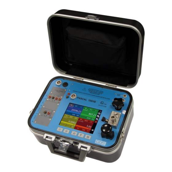
- Page 1 Operating instructions Multichannel Calibrator PASCAL 100 and PASCAL 100/IS Documenting Multivariable Multichannel Calibrator PASCAL100 / PASCAL100/IS...
- Page 2 Operating instructions PASCAL 100 Page 1 - 85 Rev. 09 – April 2017. © 2017 WIKA Alexander Wiegand SE & Co. KG All rights reserved. WIKA® is a registered trademark in various countries. Prior to starting any work, read the operating instructions!
-
Page 3: Table Of Contents
General Information......................5 Safety ..........................6 Intended use ............................7 Personnel qualification ........................... 7 Additional safety instructions for instruments with ATEX approval only Pascal 100/IS ....... 8 Special hazards ............................. 9 Labelling / safety marks ........................10 Specifications ........................11 Design and Function ....................... - Page 4 Maintenance ............................84 Cleaning ............................... 84 Recalibration ............................84 Dismounting, return and disposal .................. 85 Dismounting ............................85 Return ..............................85 Disposal ............................... 85 Declarations of conformity can be found online at www.wika.com. WIKA Operating Instruction, Pascal 100 and Pascal 100/IS...
-
Page 5: General Information
These operating instructions contain important information on handling the Multichannel ■ Calibrator model Pascal 100 or Pascal 100/IS. Working safely requires that all safety instructions and work instructions are observed. Observe the relevant local accident prevention regulations and general safety regulations for the ■... -
Page 6: Safety
Serious injuries and/or damage can occur should these not be observed. Further important safety instructions can be found in the individual chapters of these operating instructions. WIKA Operating Instruction, Pascal 100 and Pascal 100/IS... -
Page 7: Intended Use
Plugs and sockets must be protected from contamination. If the Multichannel Calibrator model Pascal 100 or Pascal 100/IS is transported from a cold into a warm environment, the formation of condensation may result in the instrument malfunctioning. -
Page 8: Additional Safety Instructions For Instruments With Atex Approval Only Pascal 100/Is
United States, as Hazardous Locations in Canada, as Potentially Explosive Atmospheres in Europe and as Explosive Gas Atmospheres by most of the rest of the world. The Pascal 100/IS intrinsically safe multichannel calibrator is designed as intrinsically safe. This means that connecting the Pascal 100/IS... -
Page 9: Special Hazards
To ensure problem-free operation, only operate the Multichannel Calibrator ■ model Pascal 100 or Pascal 100/IS on battery power. Only use the mains connection for charging the Hand-held pressure calibrators batteries. Do not apply a voltage greater than the specified voltage to the instrument. -
Page 10: Labelling / Safety Marks
Explanation of symbols Pascal 100 and Pascal 100/IS Before mounting and commissioning the Multichannel Calibrator model Pascal 100 or Pascal 100/IS, ensure you read the operating instructions! CE, European Community Instruments bearing this mark comply with the relevant European directives. -
Page 11: Specifications
3 Specifications 3 Specifications WIKA Operating Instruction, Model Pascal 100 and Pascal 100/IS... - Page 12 3 Specifications WIKA Operating Instruction, Pascal 100 and Pascal 100/IS...
- Page 13 3 Specifications WIKA Operating Instruction, Model Pascal 100 and Pascal 100/IS...
- Page 14 3 Specifications For further specifications see WIKA data sheet CT 18.01 and the order documentation. WIKA Operating Instruction, Pascal 100 and Pascal 100/IS...
-
Page 15: Design And Function
Five keys are present below the touch screen: turn on/off of the instrument, contrast settings and backlight. The electrical part of Pascal 100 or Pascal 100/IS consists from two until 4 electrical modules to be selected between the available ones (2 inputs (IN) – 2 outputs (OUT) – one HART module) for measuring and generating mA, mV, V, Hz, Ohm, Pulse, TC/RTD. -
Page 16: Scope Of Delivery
To avoid false measurements, charge the rechargeable batteries as soon as the battery indicator appears. If the batteries run too low the Pascal 100 or Pascal 100/IS will automatically shut down. Use only the original AC/DC converter which is supplied by WIKA... -
Page 17: Transport, Packaging And Storage
4 Design and Function 5 Transport, packaging and storage Transport Check the Multichannel Calibrator model Pascal 100 or Pascal 100/IS for any damage that may have been caused by transport. Obvious damage must be reported immediately. Packaging Do not remove packaging until just before mounting. -
Page 18: Commissioning, Operation
■ Electrical and temperature signals generation/simulation ■ Pressure generation and regulation ■ Environmental parameters measurement Many different configurations are available according to the specific requirements of the user. WIKA Operating Instruction, Pascal 100 and Pascal 100/IS... - Page 19 The following figure shows the output module for electrical/temperature parameters. Figure 2 – Output panel module The 2 INPUT cards and 2 OUTPUT cards are plug and play modules and can be installed by the user himself. WIKA Operating Instruction, Model Pascal 100 and Pascal 100/IS...
- Page 20 6 Commissioning, operation 6.1.2.3 Pressure module The pressure module is installed only at factory location in accordance with the Pascal 100 or Pascal 100/IS configuration required. It is possible to install two pressure modules, each one can support up to two internal and one external transducers. In total Pascal 100 can accommodate four internal and two external transducers.
- Page 21 Please consider, if the user enable the internal load resistance, this will be connected between the +HART and COM terminals. Here same examples: Transmitter HART slave Figure 4 - Case 1: 24V from module, 250Ω from module WIKA Operating Instruction, Model Pascal 100 and Pascal 100/IS...
- Page 22 6 Commissioning, operation 250 Ω Transmitter HART slave Figure 5 - Case 2: 24V from module, 250Ω external Transmitter 24V ext. HART slave Figure 6 - Case 3: 24V external, 250Ω from module WIKA Operating Instruction, Pascal 100 and Pascal 100/IS...
- Page 23 Pascal 100 or Pascal 100/IS with a multiple pin connector present in Pascal 100 or Pascal 100/IS front panel. This module is plug & play and the relevant information about the environmental parameters are displayed on the status bar at the top of the screen.
-
Page 24: Pressure
Pressure 6.2.1 Pneumatic circuit Pascal 100 or Pascal 100/IS can be equipped with four internal and two external pressure sensors. The internal sensors work only with clean dry gas (like dry air) whereas the external sensors can work with gas or liquid. Gas is related to pneumatic circuit and liquid to hydraulic circuits. - Page 25 6 Commissioning, operation There are three different pneumatic schemes available in a standard Pascal 100 or Pascal 100/IS configuration: ■ This is an example of pneumatic circuit with two sensors in parallel to the pump. One of them is protected by an overpressure valve, the other one is not protected because it has a full-scale equal to the maximum pressure generated by the pump.
-
Page 26: Electrical
Figure 12 - Circuit with four transducers Electrical The Pascal 100 or Pascal 100/IS is a multifunction calibrator. The electrical modules can be maximum four, two of them are input modules (IN A – IN B), and the other two are output modules (OUT A – OUT B). -
Page 27: Thermocouple Measurements
This temperature value is used for compensation. The Standard connector Mignon for thermocouple is shown in Figure 1. The thermoresistance for compensation of the reference cold junction is integrated in the same connector. WIKA Operating Instruction, Model Pascal 100 and Pascal 100/IS... -
Page 28: Thermoresistance Measurements
In the case of three wires connection the pin identified with the writing 3W must also be used. While for the four wires measurement, the most accurate of the above, is performed by using all four pins. WIKA Operating Instruction, Pascal 100 and Pascal 100/IS... -
Page 29: Generation Of Electrical Parameters
0.01 -50…1760 170…1760 0.01 50…1820 920…1820 0.01 -200…400 -160…400 0.01 -200…760 -200…760 0.01 -270…1300 0…1300 0.01 -270…1000 -200…1000 0.01 0…2300 0…2000 0.01 -50…1410 -50…1410 0.01 Table 5 – Thermocouple simulation table WIKA Operating Instruction, Model Pascal 100 and Pascal 100/IS... -
Page 30: Thermoresistance Simulation
In generation or simulation on any particular channel the simulated value can be rapidly changed by pressing immediately to the right of the simulated value. By pressing the displayed value a virtual numerical keyboard appears. WIKA Operating Instruction, Pascal 100 and Pascal 100/IS... -
Page 31: User Interface
6 Commissioning, operation User Interface The Pascal 100 or Pascal 100/IS calibrator has a wide display with touch screen through which it is possible to set up the instrument. The 1-, 2- or 3-window display mode shows a right column containing the following information: ■... - Page 32 Compared to the display mode for one single channel, the 1- or 2-window display mode shows additional information as follows: Figure 14 – Typical display of Pascal 100 or Pascal 100/IS with 4 windows 8. Selection of the Channel Role (None, REF, DST) 9.
-
Page 33: Channel Configuration
The following procedure shows how to configure the “C” channel on the first window and how to set up the Pascal 100 or Pascal 100/IS for temperature measurement through a Pt100 thermoresistance connected to the input pins of the IN A module (using 4 wires measurement). - Page 34 Figure 16 – Changing the Channel Letter By pressing and keeping pressed the key Q the following screen appears: Figure 17 – Selecting the Channel Letter Press the “Channel C” button to assign the Channel. WIKA Operating Instruction, Pascal 100 and Pascal 100/IS...
- Page 35 The following screen appears (depending on the installed modules): Figure 19 – Source selection As we need to measuring from the input, select the option “IN A”: The screen will change as follows: Figure 20 – IN A Selected WIKA Operating Instruction, Model Pascal 100 and Pascal 100/IS...
- Page 36 It is also possible select an Rtd type “User” if not listed in the pre-defined options. To select the Rdt type “User” press the button indicated with “Q” on the figure above. WIKA Operating Instruction, Pascal 100 and Pascal 100/IS...
- Page 37 By pressing and keep pressed that button you can enter the pages for setting the desired parameters related to the custom or user thermoresistance (Ptd). WIKA Operating Instruction, Model Pascal 100 and Pascal 100/IS...
- Page 38 ˉ7 X * 10 °C X * 10 °C Resistance @ t = 0,01 °C Value Further specific parameters can be also configured for the already configured channel by pressing the button WIKA Operating Instruction, Pascal 100 and Pascal 100/IS...
-
Page 39: Other Assignments
This data will be used in the Report function. 6.4.2 Other assignments 6.4.2.1 Pressure measurement The following procedure illustrates the setting of Pascal 100 or Pascal 100/IS for pressure measurement. The particular channel is selected by pressing the channel letter (the background of the button changes in gray) Then, press the button indicated with “Q”... - Page 40 Channel A. In this case press P for pressure. Figure 29 – Pressure parameter selection The Pascal 100 or Pascal 100/IS can be equipped with up to two pressure modules and each of them can handle up to three pressure sensors, two internals and one external with standard accuracy.
- Page 41 REF and a DUT channel has to be done. The resolution can also be changed based on the desired number of decimal digits (related to the selected engineering unit): Figure 31 – Sensor range setup WIKA Operating Instruction, Model Pascal 100 and Pascal 100/IS...
- Page 42 6 Commissioning, operation 6.4.2.2 Thermocouple signal measurement The following procedure shows the setup of Pascal 100 or Pascal 100/IS for temperature signal measurement, for example, through a thermocouple connected to the IN (input) module. The particular channel is selected by pressing the channel letter (the background of the button changes in gray) Then, press the button indicated with “Q”...
- Page 43 Figure 35 – Selecting the unit “Tc” for the module “IN A” Press the button “Tc” and the main screen changes as follows: Figure 36 – Module “IN A” with unit “Tc” selected WIKA Operating Instruction, Model Pascal 100 and Pascal 100/IS...
- Page 44 Figure 37 – Tc parameters selection: External Jc type (manual) 6.4.2.3 Electrical parameter measurement The following procedure shows the settings of Pascal 100 or Pascal 100/IS for the electrical parameters measurement through the input module. The particular channel is selected by pressing the channel letter (the background of the button changes in gray) Then, press the button indicated with “Q”...
- Page 45 The calibrator is now set on the “IN A” module, and it select the last used unit for this module (in this case the last used unit was “mV”). Press the button indicated with “Q” to change the unit from mV to Tc and the following screen appears: WIKA Operating Instruction, Model Pascal 100 and Pascal 100/IS...
- Page 46 6 Commissioning, operation Figure 41 – Selecting “mA” unit for module “IN A” By selecting the unit mA the following screen appears: Figure 42 – Unit “mA” selected for module “IN A” WIKA Operating Instruction, Pascal 100 and Pascal 100/IS...
- Page 47 In this case the option OUT A or OUT B should be selected. From the main screen, now the loop type must be selected between: passive (the calibrator Pascal supply the current loop) or active (current loop supplied externally): WIKA Operating Instruction, Model Pascal 100 and Pascal 100/IS...
- Page 48 C, or D, then the button for selecting the source: Figure 46 – Selecting module Calc Pressing CALC the followings screen is displayed: Figure 47 – Selecting assignment of channel Calc WIKA Operating Instruction, Pascal 100 and Pascal 100/IS...
- Page 49 Otherwise the channel 4 will be displayed as: Figure 49 - Calculation non possible for the Channel 4 WIKA Operating Instruction, Model Pascal 100 and Pascal 100/IS...
- Page 50 6 Commissioning, operation For the Cell Load, the channel 4C or D can calculate the result coming from a load cell connected as per the below scheme: Figure 50 – Cell Load connection WIKA Operating Instruction, Pascal 100 and Pascal 100/IS...
- Page 51 In this case, below what will be displayed: Figure 51 – Cell Load calculation Pascal 100 or Pascal 100/IS allows to manage the sensitivity of the load cell from 0 mV/V up to 9.99999 mV/V. Moreover, on channel 4C or D, the SCALING function can be assigned through the menu...
- Page 52 Then, press the button indicated with “Q” to assign the desired functional module: Figure 53 – HART Channel assign selection The following screen appears: Figure 54 – Selecting the source “HART” WIKA Operating Instruction, Pascal 100 and Pascal 100/IS...
- Page 53 Here the user has the possibility to change some HART parameters: Select the channel with active HART communication (in this case the channel A) Push the button Channel Settings to open the following screen: WIKA Operating Instruction, Model Pascal 100 and Pascal 100/IS...
- Page 54 Figure 57 – Setting the HART channel Push the button “HART FUNC” and the following screen appears: Figure 58 – HART function screen Push the button “DATA” to display the HART data: Figure 59 – HART data display WIKA Operating Instruction, Pascal 100 and Pascal 100/IS...
- Page 55 If the user wants to recalibrate the Trim. an INPUT mA measurement channel has to configured as REF channel. In addition, the loop wiring needs to flow to the IN mA terminals. If no REF mA Input channel is configured first an error will be shown. WIKA Operating Instruction, Model Pascal 100 and Pascal 100/IS...
- Page 56 The HART instrument is put in fixed mode generation (4 or 20 mA) and the REF channel is measuring the true analog mA generation. To re-align to the correct 20 mA (or 4 mA) generation press “CALIBR.” button. If needed follow the same procedure for “Zero Trim”. WIKA Operating Instruction, Pascal 100 and Pascal 100/IS...
- Page 57 Now set the REF Channel to the desired value that permits to output the transmitter the 20mA value (example 150°C). When the value is stable press ADJ. URV button. Now the transmitter will generate 4 and 20 mA between 20 °C – 150 °C. WIKA Operating Instruction, Model Pascal 100 and Pascal 100/IS...
-
Page 58: Setting Channel, Function, Instrument
If, for example, the channel is configured for thermoresistance measurements, by pressing the button “Chanel setting” the screen could be show the following parameters: Figure 65 – “IN” Channel setting WIKA Operating Instruction, Pascal 100 and Pascal 100/IS... - Page 59 With this function the user can program a ramp by automatically shifting the generation value in configurable steps. If both the 2 generation board are installed, and they are been assigned to two different channels, a different ramp for each output can be programmed. WIKA Operating Instruction, Model Pascal 100 and Pascal 100/IS...
- Page 60 Go back to the previous screen and press the button “RAMP ON” shortly to run the ramp function: the calibrator will show the main screen and on the output channel the indication “ramp” will appears (ramp active on channel B). WIKA Operating Instruction, Pascal 100 and Pascal 100/IS...
-
Page 61: Functions Setting
Figure 70 – Functions setting Here the user can set different functions grouped by: REPORT PRESET LOGGER MEMORY REPORT section: This section is intended for the reports management. For detailed information see chapter 6.7 WIKA Operating Instruction, Model Pascal 100 and Pascal 100/IS... -
Page 62: Instrument Setting
WILL NOT be deleted but a certain time should be necessary to complete the process. 6.5.3 Instrument setting This menu enables to see and change the settings of the instrument. Figure 71 – Instrument setting screen WIKA Operating Instruction, Pascal 100 and Pascal 100/IS... - Page 63 Hold All ON/OFF: press the F key to enable/disable the HOLD function on all active measuring channels. Recall Report list: press the F key load the list of the saved reports Recall Preset list: press the F key load the list of the saved presets WIKA Operating Instruction, Model Pascal 100 and Pascal 100/IS...
-
Page 64: Channel Settings
Offset Off function is activated (the button shows the indication “Offset on”). The text “OFS” on the blue bar of the main screen indicates that the function is activated. WIKA Operating Instruction, Pascal 100 and Pascal 100/IS... -
Page 65: Scaling
“Signal”. The following screen shows two channels and the first one displays the active Scaling function: WIKA Operating Instruction, Model Pascal 100 and Pascal 100/IS... -
Page 66: Hold On - Hold Off
Figure 79 – Channel with HOLD enabled 6.6.4 Modification of the generation/simulation value The generated/simulated value of an Output card or KEY can be modified from the main screen directly, by pressing the value: WIKA Operating Instruction, Pascal 100 and Pascal 100/IS... -
Page 67: Report
For the DUT: remember to define the max error and the declaration. A bargraph will be displayed on the DUT channel. When the channel is device under test, the symbol DUT will appear. Options are available on the screen for the Functions Setting (see paragraph 6.5.2.): WIKA Operating Instruction, Model Pascal 100 and Pascal 100/IS... - Page 68 Press SETUP to create a new Report. Info required are: Report name DUT model (Device Under Test) DUT Serial Number (Device Under Test) Operator Job Number Found Left Up Down N. Points WIKA Operating Instruction, Pascal 100 and Pascal 100/IS...
- Page 69 Once completed Press STORE per memorize the data. The following screen will appear: Figure 85 – Store Report request Press YES to store the report set up and then press again yes to run the report. WIKA Operating Instruction, Model Pascal 100 and Pascal 100/IS...
- Page 70 Press again OFFSET OFF to come back to the original configuration: OFS will disappear. Once the last calibration point is done, press STORE (or ABORT): the Report will end automatically and the display will go back to its original configuration. WIKA Operating Instruction, Pascal 100 and Pascal 100/IS...
- Page 71 Selecting the area with light grey background next to the report name, the SETUP of the report will be displayed: Figure 89 – Display Report setup WIKA Operating Instruction, Model Pascal 100 and Pascal 100/IS...
-
Page 72: Report Of Tc/Rtd With Dry Well Calibrator Or Dry Block Management
The Pascal calibrator can manage the following dry well calibrators: • All models of the Scandura BL-x Series • All models of the WIKA CTD-9100-x Series WIKA Operating Instruction, Pascal 100 and Pascal 100/IS... - Page 73 • WIKA model CTD-9100-1100 • Giussani’s dry well calibrators Pyros Series The models of the WIKA CTD-9100-x Series require an adapter kit for the conversion from RS-232 to RS-485. The order code for the kit is: 241113. NOTE: for some dry well calibrators a switching on safety condition could prevent the automatic setting of a set point.
- Page 74 “not defined” otherwise the Pascal Report software will be not able to run the proper report type. “Dry well type”: select the dry well calibrator connected to the Pascal calibrator WIKA Operating Instruction, Pascal 100 and Pascal 100/IS...
- Page 75 This allows to detect a stable temperature value. The value describes above depend of the type of the connected dry well calibrator and its setting specifications. WIKA Operating Instruction, Model Pascal 100 and Pascal 100/IS...
- Page 76 Run the report and the instrument display: The display shows the status “Stab. Wait. Time” with the remaining time indication. When the stabilization time is reached the instrument will enter the searching for stabilization: WIKA Operating Instruction, Pascal 100 and Pascal 100/IS...
- Page 77 The report can be imported on a PC when completed in order to be printed. The software will use the proper template based on the set “thermocouple” or “RTD” parameter: This template differs from the standard one in some freely settable fields as indicated below: WIKA Operating Instruction, Model Pascal 100 and Pascal 100/IS...
-
Page 78: Data Logger
On the LOGGER column, the following options are available: LIST set up of the Logger SETUP View Logs data DELETE ALL delete all the Logs With this function you can configure the data logger for all 4 channels simultaneously. WIKA Operating Instruction, Pascal 100 and Pascal 100/IS... - Page 79 By pressing DELETE ALL on the LOGGER column on the screen of the Functions Setting, all the logs will be deleted: a confirmation will be asked to the user before proceeding. Press the button LIST to show all the stored logs. WIKA Operating Instruction, Model Pascal 100 and Pascal 100/IS...
-
Page 80: Communication
6.10.1 Example 1 – Calibration of 2-wire pressure transmitters Pascal 100 or Pascal 100/IS generates 24 V d.c. power supply to the transmitter. The 4-20 mA output signal from the transmitter is sent to be measured to an electrical input signals card IN A or IN B. -
Page 81: Example 2 - Calibration Of Ptz Gas Volume Converters
6.10.2 Example 2 – Calibration of PTZ gas volume converters Pascal 100 or Pascal 100/IS can be used to calibrate a gas volume converter, where the absolute pressure, the temperature value and the Z factor are used to convert the gas volume measurement. -
Page 82: Example 3 - Calibration Of 4-Wire Rtd's
In this way the two measures can be compared, the calculated error is reported on the calibration report. The figure below shows the connection of the calibrator Comparison method Reference RTD DUT RTD Thermostat (Liquid Bath – Dry Block) Figure 108 – 4-wire thermoresistance calibration example WIKA Operating Instruction, Pascal 100 and Pascal 100/IS... -
Page 83: Example 4 - Calibration Of Thermocouples
You must also select the cold junction compensation if the internal, external or assigning a compensation value. The figure below shows the connection of the calibrator: Comparison method Reference TC DUT TC Thermostat (Liquid Bath – Dry Block) Figure 109 – Thermocouple calibration example WIKA Operating Instruction, Model Pascal 100 and Pascal 100/IS... -
Page 84: Gb 7 Maintenance, Cleaning And Servicing
Before cleaning, correctly disconnect the Multichannel Calibrator model Pascal 100 ■ or Pascal 100/IS from the pressure supply, and switch it off. Clean the Multichannel Calibrator model Pascal 100 or Pascal 100/IS with a moist ■ cloth. Electrical connections must not come into contact with moisture. -
Page 85: Dismounting, Return And Disposal
3. If possible, place a bag, containing a desiccant, inside the packaging. 4. Label the shipment as transport of a highly sensitive measuring instrument. Enclose the completed return form with the Multichannel Calibrator model Pascal 100 or Pascal 100/IS. The return form is available on the internet: www.wika.de / Service / Return... - Page 86 NOTES WIKA Operating Instruction, Pascal 100 and Pascal 100/IS...
- Page 87 NOTES WIKA Operating Instruction, Model Pascal 100 and Pascal 100/IS...
- Page 88 Tel. (+48) 542 3011-00 poration (Thailand) Co., Ltd Fax: (+48) 542 3011-01 850/7 Ladkrabang Road, E-Mail: info@wikapolska.pl Ladkrabang www.wikapolska.pl Bangkok 10520 Tel. (+66) 2 326 6876-80 Fax: (+66) 2 326 6874 E-Mail: info@wika.co.th www.wika.co.th WIKA Operating Instruction, Pascal 100 and Pascal 100/IS...
Need help?
Do you have a question about the PASCAL 100 and is the answer not in the manual?
Questions and answers