Sign In
Upload
Download
Table of Contents
Contents
Add to my manuals
Delete from my manuals
Share
URL of this page:
HTML Link:
Bookmark this page
Add
Manual will be automatically added to "My Manuals"
Print this page
×
Bookmark added
×
Added to my manuals
Manuals
Brands
WIKA Manuals
Test Equipment
CPH8000-ET
Operating instructions manual
WIKA CPH8000-ET Operating Instructions Manual
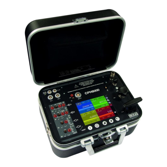
Hand-held multifunction calibrator
Hide thumbs
1
2
Table Of Contents
3
4
5
6
7
8
9
10
11
12
13
14
15
16
17
18
19
20
21
22
23
24
25
26
27
28
29
30
31
32
33
34
35
36
37
38
39
40
41
42
43
44
45
46
47
48
49
50
51
52
53
54
55
56
57
58
59
60
61
62
63
64
65
66
67
68
69
70
71
72
73
74
75
76
77
78
79
80
81
82
83
84
85
86
87
88
89
90
91
92
93
94
95
96
97
98
page
of
98
Go
/
98
Contents
Table of Contents
Bookmarks
Table of Contents
Table of Contents
General Information
Safety
Explanation of Symbols
Intended Use
Personnel Qualification
Additional Safety Instructions for Instruments with ATEX Approval Only CPH8000/IS -ET/IS
Special Hazards
Labelling / Safety Marks
Specifications
Base Instrument
Certificates
Pressure Module
Internal Sensors
External Pressure Sensor CPT8100
Electrical Signals
Electrical Input Signals
Electrical Output Signals
HART Module
Resistance Thermometer Measurement
Resistance Thermometer Simulation
Thermocouple Measurement
Thermocouple Simulation
Environmental Parameters Module
CPH8000 - IS Dimension in MM (In)
Case for Instrument Model CPH8000 - /IS
Front Panel of Model CPH8000 - /IS
Case for Instrument Model CPH8000ET - ET/IS
Front Panel of Model CPH8000 et - ET/IS
Design and Function
Description
Scope of Delivery
Power Supply
Smart Power Supply & Battery Charger Model 212009
Safety Instruction
Liability Disclaimer
LED Status Functionalities
Operating the Device
Care and Maintenance
Technical Specifications
Transport, Packaging and Storage
Trasport
Packaging
Storage
Commissioning, Operation
Commissioning
Instrument Overview CPH8000 - /IS
Instrument Overview CPH8000ET - ET/IS
Functional Modules
Input Module for Electrical/Temperature Signals
Output Module for Electrical/Temperature Signals
Pressure Module
HART Module
Environmental Parameters Module (Optional)
Pressure
Pneumatic Circuit CPH8000 - /IS (Not Avaiilable for CPH8000ET- ET/IS)
Electrical Section
Misure Segnali Elettrici
Thermocouple Measurements
Resistance Thermometer Measurements
Generation of Electrical Parameters
Thermocouple Simulation
Resistance Thermometer Simulation
User Interface
Channel Configuration
Other Assignments
Pressure Measurement
Thermocouple Signal Measurement
Electrical Parameter Measurement
Temperature Simulation
Electrical Parameter Generation
Channel D - Mathematic Functions
HART Channel Assignment
HART Trimmer Calibration
HART Scale Adjust
Setting Channel, Function, Instrument
Channel Setting
Functions Setting
Instrument Setting
Setting the "F" Key of the Keyboard
Setting the Password Field
Instrument Status Page
Channel Settings
Offset on - Offset off
Scaling
Hold on - Hold off
Filter
Ramp
Modification of the Generation/Simulation Value
Report
Report of Tc/Rtd with Dry Well Calibrator or Dry Block Management
CPH8000 Report Software
Data Logger
Communication
Calibration Examples
Example 1 - Calibration of 2-Wire Pressure Transmitters
Example 2 - Calibration of PTZ Gas Volume Converters
Example 3 - Calibration of 4-Wire Rtd's
Example 4 - Calibration of a Two-Wire Temperature Transmitter with 3 or 4-Wire Resistance Thermometer Input
Example 5 - Calibration of Thermocouples
Example 6 - Calibration of a Two-Wire Temperature Transmitter with Thermocouple Input
Maintenance, Cleaning and Servicing
Maintenance
Cleaning
Recalibration
Dismountig, Return and Disposal
Dismounting
Return
Disposal
Advertisement
Quick Links
Download this manual
Operating instructions
EN
Hand-held multifunction calibrator CPH8000-ET and CPH8000/IS-ET/IS
Documenting Multivariable Multichannel Calibrator CPH8000 - ET and CPH8000/IS - ET/IS
Table of
Contents
Previous
Page
Next
Page
1
2
3
4
5
Advertisement
Table of Contents
Need help?
Do you have a question about the CPH8000-ET and is the answer not in the manual?
Ask a question
Questions and answers
Related Manuals for WIKA CPH8000-ET
Test Equipment WIKA Wally Box III CPH7600 Operating Instructions Manual
Portable pressure calibrator (92 pages)
Test Equipment WIKA Wally Box III Operating Instructions Manual
Hand-held pressure calibrator, wally box iii (76 pages)
Test Equipment WIKA CPH7650 Operating Instructions Manual
Portable pressure calibrator (116 pages)
Test Equipment WIKA CPH7650 Operating Instructions Manual
Portable pressure calibrator (144 pages)
Test Equipment WIKA CPH65I0 Operating Instructions Manual
Intrinsically safe hand-held pressure calibrator (80 pages)
Test Equipment WIKA CPH65I0 Operating Instructions Manual
Intrinsically-safe hand-held pressure calibrator (100 pages)
Test Equipment WIKA CPH7000 Manual
Portable process calibrator. (15 pages)
Test Equipment WIKA CPH7000 Operating Instructions Manual
Portable process calibrator (128 pages)
Test Equipment WIKA CPH6600 Operating Instructions Manual
Hand-held pressure calibrator with integrated pump (96 pages)
Test Equipment WIKA PASCAL 100 Operating Instructions Manual
(88 pages)
Test Equipment WIKA CPH8000 Operating Instructions Manual
(85 pages)
Test Equipment WIKA CPH6000 Operating Instructions Manual
(129 pages)
Test Equipment WIKA CPH6000 Operating Instructions Manual
Pressure calibrator (112 pages)
Test Equipment WIKA CPH8000/IS Operating Instructions Manual
Hand-held multifunction calibrator (98 pages)
Test Equipment WIKA CPG1000 User Manual
Precision digital pressure gauge (7 pages)
Test Equipment WIKA CPB 5000 Operating Instructions Manual
Pressure balance (80 pages)
This manual is also suitable for:
Cph8000/is
Cph8000et/is
Table of Contents
Print
Rename the bookmark
Delete bookmark?
Delete from my manuals?
Login
Sign In
OR
Sign in with Facebook
Sign in with Google
Upload manual
Upload from disk
Upload from URL


Need help?
Do you have a question about the CPH8000-ET and is the answer not in the manual?
Questions and answers