
Related Manuals for WIKA CEP6000


Summary of Contents for WIKA CEP6000
- Page 1 Operating instructions 操作说明书 Hand-held multi-function calibrator, model CEP6000 CEP6000 型手持多功能校准仪 Hand-held multi-function calibrator, model CEP6000 CEP6000 型手持多功能校准仪...
- Page 2 Operating instructions model CEP6000 Page 3 - 50 CEP6000 型操作说明书 51 - 100 页码 © 2014 WIKA Alexander Wiegand SE & Co. KG All rights reserved. 保留一切权利。/ Alle Rechte vorbehalten. WIKA is a registered trademark in various countries. ® WIKA ®...
-
Page 3: Table Of Contents
6.2.10 Menu function “ZERO” ......21 6.2.11 Menu function “Parameter selection” ....22 WIKA operating instructions, model CEP6000... - Page 4 9.3 Disposal ........42 10. Specifications 11. Accessories Appendix: EC declaration of conformity Declarations of conformity can be found online at www.wika.com. WIKA operating instructions, model CEP6000...
-
Page 5: General Information
1. General information 1. General information The model CEP6000 hand-held multi-function calibrator described in these operating ■ instructions has been manufactured using state-of-the-art technology. All components are subject to stringent quality and environmental criteria during production. Our management systems are certified to ISO 9001 and ISO 14001. -
Page 6: Short Overview
One test cable is used for the measurement signal. 4-wire measurement Two test cables are used for the voltage supply. Two test cables are used for the measurement signal. Cold junction compensation 2. Short overview 2.1 Overview Display Keypad Connections WIKA operating instructions, model CEP6000... -
Page 7: Description
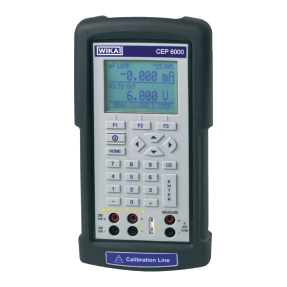
2. Short overview 2.2 Description The model CEP6000 hand-held multi-function calibrator is a battery-operated hand-held instrument which can measure or simulate electrical parameters. The model CEP6000 works with different thermocouples and resistance thermometers, among others. Very high accuracy and diverse special functions make the instrument to a user-friendly and highly flexible calibration instrument. -
Page 8: Safety
RTD’s, TC’s, frequency and pulses. In addition, external pressure sensors/pressure modules can be connected which enable pressure to measure with this calibrator. The WIKA model CPT6600 pressure modules and the Mensor model CPT6100/CPT6180 precision pressure sensors are compatible here. -
Page 9: Improper Use
Do not use the instrument within hazardous areas. ▶ Only use accessories provided by WIKA. Any use beyond or different to the intended use is considered as improper use. Do not use this instrument in safety or emergency stop devices. -
Page 10: Personnel Qualification
Special operating conditions require further appropriate knowledge, e.g. of aggressive media. 3.6 Labelling, safety marks Product label The product label is located on the side of the instrument beneath the protective rubber boot. Binary code Serial no. WIKA operating instructions, model CEP6000... -
Page 11: Design And Function
RTD’s, TC’s, frequency and pulses. In addition, external pressure sensors/pressure modules can be connected which enable pressure to measure with this calibrator. The WIKA model CPT6600 pressure modules and the Mensor model CPT6100/CPT6180 precision pressure sensors are compatible here. -
Page 12: Connections
Terminals for the simulation and measurement of voltage, frequency, pulse trains and resistance thermometers (RTDs). Current, resistance thermometers (3-wire, 4-wire), input/output Terminals for the simulation and measurement of current and also for resistance thermom- eter measurements with 3- and 4-wire connection. WIKA operating instructions, model CEP6000... -
Page 13: Key Function
The last numerical value input will be deleted. ENTER Confirms the input of numerical values. Numeric keys Used for the input of numerical values. HOME, returns to main menu Reverts back to the start menu on the menu bar. WIKA operating instructions, model CEP6000... -
Page 14: Batteries
ON/OFF Switches the calibrator on and off. 4.2 Batteries 4.2.1 Selecting the batteries or rechargeable batteries The model CEP6000 works with four alkaline batteries (AA) or with four NiMH rechargeable batteries (AA). 4.2.2 Using the power supply unit CAUTION! Physical injuries and damage to property and the environment... -
Page 15: Transport, Packaging And Storage
5. Transport, packaging and storage 5. Transport, packaging and storage 5.1 Transport Check the model CEP6000 hand-held multi-function calibrator for any damage that may have been caused by transport. Obvious damage must be reported immediately. CAUTION! Damage through improper transport With improper transport, a high level of damage to property can occur. -
Page 16: Commissioning, Operation
▶ Do not touch the metal parts at the test cables. As soon as the model CEP6000 hand-held multi-function calibrator is turned on, by pressing the ON/OFF key, it will go through a short self-test routine. During this routine, the display shows the current firmware version and the auto-shutdown status. The calibrator requires a maximum of 5 minutes warm-up to reach its specified accuracy. -
Page 17: Main Display
Displays the current measured value with respect to 4 mA = 0 % and 20 mA = 100 %. Units Displays the corresponding unit for measurement or output/simulation. For “RTD” (resistance thermometer) and “TC” (thermocouple), °C or °F are offered; for “FREQ” (frequency) and “PULSE” (pulse), CPM, Hz or kHz. WIKA operating instructions, model CEP6000... -
Page 18: Menu Bar
6.2.1 Menu function “Measuring” In the start menu for the function “Measuring”, only the options “MENU” and “LIGHT” are active. The option “MENU” calls the next menu level to the menu bar, i.e. to call the main WIKA operating instructions, model CEP6000... -
Page 19: Menu Function "Output
With “UPPER”, the selection menu for the parameters of the upper display will be called. With “LOWER”, the selection menu for the parameters of the lower display will be called. “MORE” switches to the next menu level. UPPER LOWER MORE WIKA operating instructions, model CEP6000... -
Page 20: Menu Function "Automatic Output Function
The option “AUTO OFF” acts to switch on and off the automatic switch-off function and specifies how long the instrument remains in standby before it switches off. “NEXT” switches to the next menu function and “DONE” returns to the start menu. AUTO OFF NEXT DONE WIKA operating instructions, model CEP6000... -
Page 21: Menu Function "Frequency Or Pulse Output
The option “ZERO” acts to reset the pressure to zero. “NEXT” switches to the next menu function and “DONE” returns to the start menu. For further information on resetting to 0, see chapter 6.4.4 “Measuring pressure”. ZERO NEXT DONE WIKA operating instructions, model CEP6000... -
Page 22: Menu Function "Parameter Selection
3. Connect the test cables (see following figure). VOLTS IN -0.000 V MEASURE / SOURCE MEASURE VOLTS IN – Ω Loop 5.000 V – – mA– MENU LIGHT Measuring voltage and frequency with the input and output terminals WIKA operating instructions, model CEP6000... -
Page 23: Gb 6.4.2 Measuring Current (Ma)
To measure temperature with the thermocouple, follow the steps below: 1. Connect the wires of the thermocouple to the input/output of the calibrator using the thermocouple mini-connector (see following figure). WIKA operating instructions, model CEP6000... - Page 24 To measure temperature with resistance thermometers, follow the steps below: 1. In the main menu, switch to the lower display “LOWER” and select “RTD”. 2. The input/output setting must be set to “IN”. 3. Select 2-, 3- or 4-wire connection “2W, 3W, 4W”. WIKA operating instructions, model CEP6000...
-
Page 25: Measuring Pressure
3. Connect the pressure module to the pressure line. ATTENTION! Damage to the threaded connections The pressure module can be damaged by over-tightening the threaded connection. ▶ Use suitable tools. ▶ Tighten the pressure connection with a maximum of 13.6 Nm (torque spanner). WIKA operating instructions, model CEP6000... - Page 26 1. Connect the pressure module to the calibrator using the pressure module adapter (see following figure). For the connection of the pressure module to the calibrator, a WIKA pressure module adapter must be used. 2. From the main menu, switch to the upper or lower display as required. The calibrator measures pressure in the upper as well as the lower display.
-
Page 27: Using The Output Modes (Lower Display)
6. Repeat these steps with (for example) 20 V and hold down the function key for “100 %” [F3]. 7. With the function key for “25 %”, it is now possible to move between 5 V and 20 V in steps of 25 %. WIKA operating instructions, model CEP6000... -
Page 28: Using The Automatic Output Functions
4. Enter the desired current value via the keypad. mA LOOP -25.00 % 0.000 mA MEASURE MEASURE / SOURCE mA OUT 5.000 mA – Ω Loop – – mA– MENU LIGHT Connection for use as a mA source WIKA operating instructions, model CEP6000... - Page 29 The CEP6000 can be configured so that the 250 Ω resistor for HART™ compatible instruments can be activated within the CEP6000. If the internal 250 Ω resistor within the CEP6000 is used, a serial resistance for the calibration of HART™ modules must not be activated.
-
Page 30: Simulating A Transmitter
4. Enter the desired voltage value via the keypad. mA LOOP -25.00% 0.000 mA MEASURE / SOURCE MEASURE mA OUT Ω 6.000 V Loop – – mA– – MENU LIGHT Connections for voltage, frequency and pulse outputs WIKA operating instructions, model CEP6000... -
Page 31: Frequency Output
To simulate a thermocouple, follow the steps below: 1. Connect the wires of the thermocouple to the input/output of the calibrator using the thermocouple mini-connector (see following figure). 2. In the main menu, switch to the lower display “LOWER” and select “TC”. WIKA operating instructions, model CEP6000... -
Page 32: Simulating Resistance Or Resistance Thermometers
6. Enter the temperature value or resistance value, respectively, via the keypad. mA LOOP -25.00% 0.000 mA RTD OUT P500-385 10.0 °C MEASURE / SOURCE MEASURE Ω Loop – – mA– LIGHT MENU Simulating resistance or resistance thermometers WIKA operating instructions, model CEP6000... - Page 33 ▶ Minimum temperature ▶ Maximum temperature ▶ ▶ Temperature coefficients The custom function uses the Callendar–Van Dusen equation for output and measure- ment of custom resistance thermometers. The coefficient C is used only for temperatures WIKA operating instructions, model CEP6000...
-
Page 34: Using The Isolated Measuring Modes (Upper Display)
To test a 2-wire transmitter, which has an external power supply that is not connected, use the function for separate voltage supply. This function activates a DC 24 V voltage supply in series with the measuring current loop. WIKA operating instructions, model CEP6000... -
Page 35: Using The Upper And Lower Displays For Test And Calibration
2. The input/output setting must be set to “OUT”. 3. Connect the test cables to the calibrator (see following figure). Maximum current: 1 mA MEASURE / SOURCE MEASURE Ω Loop – – mA– Connection of a display instrument WIKA operating instructions, model CEP6000... -
Page 36: Calibrating An I/P Instrument
6.7.3 Calibrating a transmitter To calibrate a transmitter, both displays (“UPPER” and “LOWER”) are used - the upper display for measurement and the lower for output/simulation. In this example, a thermo- couple transmitter is calibrated. WIKA operating instructions, model CEP6000... -
Page 37: Calibrating A Pressure Transmitter
2. In the main menu, switch to the lower display “LOWER” and select “PRESSURE”. 3. Connect the calibrator with the mA input to the mA output of the pressure transmitter. In addition, connect the external pressure module with the pressure connection of the WIKA operating instructions, model CEP6000... -
Page 38: Faults
CAUTION! Physical injuries and damage to property and the environment If faults cannot be eliminated by means of the listed measures, the model CEP6000 hand-held multi-function calibrator must be shut down immedi- ately. ▶ Ensure that pressure or signal is no longer present and protect against accidental commissioning. - Page 39 System error Switch off the instrument, wait for a short period of time, switch on again Instrument faulty Send instrument in for repair WIKA operating instructions, model CEP6000...
-
Page 40: Maintenance, Cleaning And Recalibration
Replacing the batteries To eliminate measuring errors, change the batteries as soon as the battery symbol is displayed. If the battery capacity is too low, the CEP6000 will automatically switch off in order to prevent electrolyte escaping. To replace the batteries or rechargeable batteries, follow the steps below: 1. -
Page 41: Recalibration
9.2 Return Strictly observe the following when shipping the instrument: All instruments delivered to WIKA must be free from any kind of hazardous substances (acids, bases, solutions, etc.) and must therefore be cleaned before being returned. WARNING! Physical injuries and damage to property and the environment... -
Page 42: Disposal
This marking on the instruments indicates that they must not be disposed of in domestic waste. The disposal is carried out by return to the manufacturer or by the corresponding municipal authorities (see EU directive 2002/96/EC). WIKA operating instructions, model CEP6000... -
Page 43: Specifications
250 Ω (activatable) ® Communication Interface RS-232, USB with optional serial adapter Voltage supply Power supply 4 x 1.5 V AA batteries Battery life 20 hours Battery status indication Icon in display for low battery level WIKA operating instructions, model CEP6000... - Page 44 2004/108/EC, EN 61326 emission (group 1, class B) and interference immunity (portable test and measuring equipment) Certificate Calibration Standard: 3.1 calibration certificate per DIN EN 10204 Option: DKD/DAkkS calibration certificate Approvals and certificates, see website WIKA operating instructions, model CEP6000...
- Page 45 0.05 % ±0.01 kHz Pulse Output 1 ... 30,000 counts 2.0 CPM ... 10.0 kHz Pressure Input dependent on pressure module 1) Selectable amplitude of 1 ... 20 V based on a square wave 2) Counts per minute WIKA operating instructions, model CEP6000...
- Page 46 0.4 °C Type N -200.0 ... -100.0 °C 0.8 °C 1.0 °C -99.9 ... +1,300.0 °C 0.3 °C 0.5 °C 3) Error of cold junction compensation outside of 23 ± 5 °C is 0.05 °C/°C. WIKA operating instructions, model CEP6000...
- Page 47 0.3 °C Cu100 -180.0 ... +200.0 °C 0.1 °C YSI400 15.0 ... 50.0 °C 0.1 °C 4) Accuracy based on 4-wire connection For further specifications see WIKA data sheet CT 83.01 and the order documentation. WIKA operating instructions, model CEP6000...
- Page 48 10. Specifications Dimensions in mm Front view Side view Top view WIKA operating instructions, model CEP6000...
-
Page 49: Accessories
Thermocouple cable set R/S, N, B with plugs ■ Beryllium copper cable with low thermoelectric voltage (red) ■ Beryllium copper cable with low thermoelectric voltage (black) ■ Test cables, one pair of cables (red/black) ■ Other Service case ■ WIKA operating instructions, model CEP6000... -
Page 50: Appendix: Ec Declaration Of Conformity
Appendix: EC declaration of conformity WIKA operating instructions, model CEP6000... - Page 51 6.2.10 菜单功能“归零” ......69 6.2.11 菜单功能“参数选择”......69 WIKA 操作说明书(型号:CEP6000)...
- Page 52 9.3 处置 ........90 10. 规格 11. 附件 附录:EC 符合性声明 符合性声明请见 www.wika.com。 WIKA 操作说明书(型号:CEP6000)...
-
Page 53: 一般信息
1.一般信息 1. 一般信息 本操作说明书所述的 CEP6000 型手持多功能校准仪采用一流的技术制造而成。所有 ■ 元件在生产过程中都恪守严格的质量和环境标准。我们的管理体系通过了 ISO 9001 和 ISO 14001 认证。 本操作说明书包含重要的仪器处理信息。工作安全法规要求遵守所有的安全指令和工 ■ 作指令。 请遵守适用于本仪器使用范围的当地事故预防条例和一般安全法规。 ■ 操作说明书是产品的一部分,必须与仪器一起放置,便于熟练的操作人员随时取用。 ■ 如果更换仪器的操作人员或所有者,必须一同移交本操作说明书。 熟练的操作人员在开始任何工作之前,必须仔细阅读并理解本操作说明书。 ■ 销售文档中包含的一般条款和条件适用本仪器。 ■ 将来可能进行技术修改。 ■ 已根据国际标准执行工厂校准 / DKD/DAkkS 校准。 ■ 更多信息: ■ - 网址: www.wika.com.cn / www.wika.com - 相关数据表:... -
Page 54: 简介
1.一般信息 / 2.简介 缩写、定义 电阻温度计 热电偶 2 线测量 两条测试线缆用于电源。 测量信号也提供电流。 3 线测量 两条测试线缆用于电源。 一条测试线缆用于测量信号。 4 线测量 两条测试线缆用于电源。 两条测试线缆用于测量信号。 冷端温度补偿 2. 简介 2.1 概述 显示屏 键盘 连接 WIKA 操作说明书(型号:CEP6000)... -
Page 55: 说明
2.简介 2.2 说明 CEP6000 型手持多功能校准仪是电池供电的手持仪器,可以测量或模拟电气参数。 CEP6000 型号支持各种不同的热电偶和电阻温度计。 超高准确度和各项特殊功能使本仪器成为一款简便易用、高度灵活的校准仪。 2.3 交付产品 CEP6000 型手持多功能校准仪 ■ 操作说明书 ■ 三套测试线缆(红色/黑色) ■ 符合 DIN EN 10204 的 3.1 校准证书 ■ 四节 AA 电池 ■ 保护橡胶套 ■ 快速入门指南 ■ 按照装箱单交叉检查交付产品。 WIKA 操作说明书(型号:CEP6000)... -
Page 56: 安全性
3.1 符号说明 警告! ... 表示潜在的危险情况,如不避免,可导致严重人身伤害或死亡。 小心! ... 表示潜在的危险情况,如不避免,可导致轻微人身伤害或设备损坏, 或可能造成环境破坏。 危险! ... 表示电源造成的危险。如果不遵守安全说明,可能导致严重或致命 伤害。 提示 ... 表示有帮助的提示、建议和信息,以供高效无故障运行之需。 3.2 预期用途 CEP6000 型手持多功能校准仪是电池供电的手持仪器,可以测量并输出和/或模拟电流、 电压、电阻、RTD、TC、频率和脉冲。 此外,还可以连接外部压力传感器/压力模块,通过本校准仪来测量压力。WIKA 型号 CPT6600 压力模块和 Mensor 型号 CPT6100/CPT6180 精密压力传感器都兼容。 本仪器不允许在危险区域使用! 本仪器专为此处所述的预期用途设计和制造,不得另作他用。 必须严格遵守本操作说明书所载的技术规格。如因仪器操作或处理不当而导致超出其技术 规格,必须立即停止使用仪器,并交由授权的 WIKA 服务工程师进行检查。 必须以要求的谨慎程度对待本精密电子仪器(防止潮湿、碰撞、强磁场、静电和极端温 度,切勿将任何物体插入本仪器或其开口中)。必须防止插头和插座遭到污染。 对于因非预期用途操作而产生的任何索赔,制造商概不负责。 WIKA 操作说明书(型号:CEP6000)... -
Page 57: 使用不当
3.安全性 3.3 使用不当 警告! 使用不当会导致伤害 仪器使用不当可能导致危险的情况和伤害。 ▶ 不得擅自修改仪器。 ▶ 切勿在危险区域使用仪器。 ▶ 只能使用 WIKA 提供的附件。 任何不符合预期用途或超出其范围的使用都视为使用不当。 切勿将本仪器用于安全或紧急停止设备。 3.4 操作人员的责任 本仪器用于工业领域。因此,操作人员负责有关工作安全的法律责任。 必须遵守本操作说明书中的安全说明,以及安全、事故预防和环境保护法规。 WIKA 操作说明书(型号:CEP6000)... -
Page 58: 人员资质
3.安全性 3.5 人员资质 警告! 操作人员不符合资质可能导致人身伤害 处理不当可能导致严重人身伤害和设备损坏。 ▶ 本操作说明书所述的操作只可由具有下列资格的熟练操作人员进行。 熟练的操作人员 熟练的操作人员(获得操作人员的授权)是指基于其技术培训、测量和控制技术知识,及 其对国家特定法规、当前标准和指令的了解与经验,有能力执行所述工作,并能独立辨识 潜在危险的人员。 特殊操作条件要求更多相关的知识,例如腐蚀性介质。 3.6 标签、安全标志 产品标签 产品标签位于仪器侧面的保护橡胶套下方。 二进制代码 序列号 WIKA 操作说明书(型号:CEP6000)... -
Page 59: 设计和功能
3.安全性 / 4.设计和功能 符号 在调试仪器之前,确保先阅读本操作说明书! 具有此标记的仪器符合相关的欧盟指令。 仪器上的此标记表示不能作为家庭垃圾处理。可以返还给制造商或相应的 市政机关(请参见欧盟指令 2002/96/EC)。 4. 设计和功能 CEP6000 型手持多功能校准仪是电池供电的手持仪器,可以测量并输出和/或模拟电流、 电压、电阻、RTD、TC、频率和脉冲。 此外,还可以连接外部压力传感器/压力模块,通过本校准仪来测量压力。WIKA 型号 CPT6600 压力模块和 Mensor 型号 CPT6100/CPT6180 精密压力传感器都兼容。 4.1 前箔 下图显示输入和输出端子的位置,以及校准仪上按钮的位置。 WIKA 操作说明书(型号:CEP6000)... -
Page 60: 连接
CEP6000 HOME – MEASURE / SOURCE MEASURE Ω Loop – – mA– 外部压力模块的连接 校准仪在连接压力模块后可测量压力。 串行接口 校准仪连接 PC 后可进行远程操作。 (单独)电流和电压输入以及 24 V 直流电压的输出 电流、电压和单独电流环路电源的测量端子。 热电偶输入/输出 热电偶的测量或模拟端子。适用于热电偶的极化微型连接器。 电压、电阻温度计(2 线)、频率、脉冲、输入/输出 电压、频率、脉冲序列和电阻温度计 (RTD) 的模拟和测量端子。 电流、电阻温度计(3 线、4 线)、输入/输出 电流的模拟和测量端子,还适用于 3 线和 4 线连接的电阻温度计测量。 WIKA 操作说明书(型号:CEP6000)... -
Page 61: 按键功能
4.设计和功能 4.1.2 按键功能 CEP6000 HOME – MEASURE / SOURCE MEASURE Ω Loop – – mA– 显示屏 校准仪显示屏底部用于操作菜单栏的功能键 [F1] 键用于选择左侧框中的选项,[F2] 键用于选择中间框中的功能,[F3] 键用于选择右侧框中 的功能。 修改输出值的个别数字:增大、减小或坡道输出值 使用左右箭头键选择要更改输出值中的哪个数字。使用上下箭头键可以增大、减小输出值或切 换到坡道形式。 清除输入值 将删除输入的最后一个数值。 ENTER 确认数值输入。 数字键 用于输入数值。 HOME - 返回主菜单 返回到菜单栏上的开始菜单。 开启/关闭 开启和关闭校准仪。 WIKA 操作说明书(型号:CEP6000)... -
Page 62: 电池
4.设计和功能 4.2 电池 4.2.1 选择电池或充电式电池 CEP6000 型号支持四节碱性电池 (AA) 或四节 NiMH 充电式电池 (AA)。 4.2.2 使用电源设备 小心! 身体伤害以及财产和环境损害 如果 CEP6000 型手持多功能校准仪中装有碱性电池,同时又使用电源设 备,可能发生过热、严重损坏和泄漏。电池电解液泄漏可能严重损害健 康。 ▶ 本仪器只能在未装电池时使用电源设备,或者使用 NiMH 充电式电池。 ▶ 只能使用未损坏、无故障的电源设备。 ▶ 请使用 WIKA 附件。 使用电源设备: 1. 从 CEP6000 型手持多功能校准仪中取出电池,或者在校准仪的电池盒中装入充电式 电池。 2. 将电源设备连接到校准仪。 3. 将电源线插入电源连接器。... -
Page 63: 运输、包装和存放
5.运输、包装和存放 5. 运输、包装和存放 5.1 运输 检查 CEP6000 型手持多功能校准仪是否在运输过程中造成任何损坏。 必须及时报告明显的损坏。 小心! 运输不当会造成损坏 运输不当可能严重损害财产。 ▶ 交货时卸下包装的货物以及内部搬运期间,请小心处理并遵循包装上的 符号。 ▶ 在内部搬运时,遵守第 5.2 章“包装和存放”中的说明。 如果仪器从寒冷的地方搬运到温暖的环境,冷凝可能导致仪器故障。在运行之前,先让仪 器温度达到室温。 5.2 包装和存放 只有在使用时才能拆下包装。 请保留包装材料,以便在下次运输过程中提供最佳保护(例如使用地变更、送修等)。 存放地点的允许条件: 存放温度:-20 ...+70 °C ■ 湿度:0 ...90 % 相对湿度(无凝结) ■ 避免置于以下状况中: 阳光直射或靠近高温物体 ■ 机械振动、机械冲击(用力放下) ■... -
Page 64: 调试、操作
6. 调试、操作 注意! 电击会导致损坏 电压高于额定值可能会损坏多功能校准仪。外壳或测试线缆如有损坏,任 何接触都可能导致电击。 采用正确的额定电压,请参见第 10 章“规格”。 ▶ ▶ 请勿使用已损坏的校准仪。使用之前,请检查校准仪的外壳。注意是否 缺少塑料组件或是否有裂纹,特别是接口周围的绝缘层。 ▶ 请勿使用有故障的校准仪。仪器保护可能受损。如有疑问,请专人检查 校准仪。 ▶ 电池盒必须关闭并密封。 ▶ 显示电池符号时,立即更换电池。 ▶ 测量或模拟时务必使用正确的连接器插座、功能和量程。 ▶ 仅当所有线缆都已从校准仪断开连接后才能开启电池盒。 ▶ 请检查测试线缆有无绝缘损坏或金属组件裸露。检查测试线缆的连续 性。使用校准仪之前更换所有损坏的测试线缆。 ▶ 切勿触碰测试线缆上的金属部分。 只要通过按下 ON/OFF 键开启了 CEP6000 型手持多功能校准仪,校准仪就会进行一次 例行的短暂自检。在自检期间,显示屏将显示当前的固件版本和自动关机状态。校准仪 至少需要预热 5 分钟才会达到其指定的准确度。环境温度变化大时,可能需要更长的预 热时间。 WIKA 操作说明书(型号:CEP6000)... -
Page 65: 主显示屏
0.000 mA RTD IN 4W P10-385 °C MENU LIGHT 数字显示 显示测量信号或模拟信号的数值。 “OL”或“-OL”测量值表示超出量程。 量程的显示 仅适用于“mA”和“mA LOOP”显示。 显示关于 4 mA = 0 % 和 20 mA = 100 % 的电流测量值。 单位 显示测量或输出/模拟的相应单位。 对于“RTD”(电阻温度计)和“TC”(热电偶),提供 °C 或 °F;对于“FREQ” (频率)和“PULSE”(脉冲),提供 CPM、Hz 或 kHz。 WIKA 操作说明书(型号:CEP6000)... -
Page 66: 菜单栏
(压力)、“mA IN”(输入电流,以 mA 表示)和“mA LOOP”(24 V 直流 电压时的 mA)。 下部显示区可用的选项包括:“VOLTS”(电压)、“TC”(热电偶)、 “RTD”(电阻温度计)、“FREQ”(频率)、“PULSE”(脉冲)、 “PRESSURE”(压力)和“mA”(电流)或“mA 2W SIM”(电流模拟)。 6.2 菜单栏 显示参数通过位于 LCD 显示屏底部的菜单栏管理。功能键 [F1]、[F2] 和 [F3] 用于导航菜 单栏的所有层级和选项。最上层菜单是开始菜单。 可随时按 [HOME] 键返回此菜单。开始菜单有三种形式:输入开始菜单、输出开始菜单和 脉冲开始菜单。 6.2.1 菜单功能“测量” 在功能“测量”的开始菜单中,只启用选项“MENU”和“LIGHT”。选项“MENU”用 于将下一级菜单调用到菜单栏,即调用主菜单。按下相应的功能键 [F1] 可调用主菜单。 选项“LIGHT”用于开启 LCD 显示屏的背光。按下相应的功能键 [F2] 可开启背光。 MENU LIGHT WIKA 操作说明书(型号:CEP6000)... -
Page 67: 菜单功能"输出
能”。只要退出该菜单或按下 [HOME] 键,自动输出功能就会停止。 MENU LIGHT STEP 6.2.3 菜单功能“脉冲输出” 脉冲开始菜单也有三个可用的选项:“MENU”、“TRIG”和“COUNTS”。 选项“TRIG”和“COUNTS”用于脉冲模拟。这些选项的功能说明请参见第 6.5.7 章 “脉冲输出”。 MENU TRIG COUNTS 6.2.4 菜单功能“UPPER”、“LOWER”和“MORE” 菜单栏的下一级是主菜单本身。主菜单下哪些层级可用取决于所选的校准仪操作模式。选 项包括“UPPER”、“LOWER”和“MORE”。 选择“UPPER”时,将会调用上部显示区参数的选择菜单。选择“LOWER”时,则会调 用下部显示区参数的选择菜单。“MORE”将切换至下一级菜单。 UPPER LOWER MORE 6.2.5 菜单功能“自动输出功能” “自动输出功能”是“输出”模式下的菜单功能,通过按“MORE”调用。选项包括 “AUTO FUNC”、“NEXT”和“DONE”。 选择“AUTO FUNC”时,可以设定自动输出功能的参数。“NEXT”用于切换至下一个 菜单功能,“DONE”用于返回开始菜单。有关详细信息,请参见第 6.5.2 章“使用自动 输出功能”。 AUTO FUNC NEXT DONE WIKA 操作说明书(型号:CEP6000)... -
Page 68: 菜单功能"对比度
于返回开始菜单。选择“CONTRAST”后会显示箭头键 [F1, F2],用以设定对比度。 在特定情况下,对比度变化大可能导致显示屏在正常条件下难以显示。如果显示屏对于要 显示的值太亮或太暗,应采取以下步骤将对比度设定重置为默认值。 1. 按住 [HOME] 键,同时开启仪器。 2. 按住此按钮 10 秒钟即可将对比度重置为工厂设定。如果显示屏太亮以至于无法看清仪 器是开启还是关闭,可使用背光对应的按钮确认。 CONTRAST NEXT DONE 6.2.7 菜单功能“自动关闭” 自动关闭的主菜单包含选项“AUTO OFF”、“NEXT”和“DONE”。 选项“AUTO OFF”用于开启和关闭自动关闭功能,以及指定仪器在关闭之前保持待机状 态的时长。“NEXT”用于切换至下一个菜单功能,“DONE”用于返回开始菜单。 AUTO OFF NEXT DONE 6.2.8 菜单功能“频率或脉冲输出” 当下部显示区用于频率和脉冲输出时,在主菜单后还会显示频率子菜单。选项包括 “FREQ LEVEL”、“NEXT”和“DONE”。 “FREQ LEVEL”用于设定振荡幅度。“NEXT”用于切换至下一个菜单功能, “DONE”用于返回开始菜单。 FREQ LEVEL NEXT DONE WIKA 操作说明书(型号:CEP6000)... -
Page 69: 菜单功能"探头特定系数
菜单功能“归零” 将压力重置为零值是在主菜单中选择“MORE”时的最后一个选项,仅在连接了外部压力 传感器时才会显示。选项包括“ZERO”、“NEXT”和“DONE”。 “ZERO”用于将压力重置为零。“NEXT”用于切换至下一个菜单功能,“DONE”用 于返回开始菜单。有关重置为 0 的更多信息,请参见第 6.4.4 章“测量压力”。 ZERO NEXT DONE 6.2.11 菜单功能“参数选择” 参数选择菜单通过主菜单使用“UPPER”或“LOWER”调用。选项包括“SELECT”、 “NEXT”和“DONE”。选择后,一个参数会在显示屏中闪烁。 使用选项“SELECT”可更改参数。选择“NEXT”可切换至另一个变量。“DONE”用 于切换回开始菜单并接受选择。 SELECT NEXT DONE 6.3 光标控制/设定点控制 可使用键盘上的四个箭头键更改输出值。如果按下箭头键,光标会出现在输出值的最后一 位数下面。使用左右箭头键选择要更改输出值中的哪个数字。使用上下箭头键可以增大或 减小输出值。按下四个箭头键中的任何一个,菜单栏都将切换到设定点菜单。 100% 三个功能键分别赋值“0 %”、“25 %”和“100 %”。同时按下相应的功能键时,0 和 100 % 可通过输入值来保存。“25 %”对应的按键然后会将相应的值切换至 25 %。 WIKA 操作说明书(型号:CEP6000)... -
Page 70: 使用测量代码(下部显示区
MENU LIGHT 测量输入和输出端子的电压和频率 6.4.2 测量电流 (mA) 要测量电流 (mA),请执行以下步骤: 1. 在主菜单中,切换到下部显示区“LOWER”并选择“mA”。 2. 输入/输出设定必须设为“IN”。 3. 连接测试线缆(请参见下图)。 mA IN -25.00% 0.000 mA MEASURE / SOURCE MEASURE – Ω mA IN Loop – – mA– 5.000 mA MENU LIGHT 测量输入和输出端子的电流 (mA) WIKA 操作说明书(型号:CEP6000)... -
Page 71: 测量温度
°C 功能将会激活,测量热电偶的有效温度。如果选项 “CJC”禁用,校准仪将测量连接点热电偶与热电偶 MENU LIGHT 输入端子之间的温差。 CJC 选项应仅在通过外部冰槽进行校准时才予以禁用。 要使用热电偶测量温度,请执行以下步骤: 1. 使用迷你连接器将热电偶的线缆连接到校准仪的输入/输出端(请参见下图)。 热电偶的连接线必须与校准的热电偶类型匹配。 2. 在主菜单中,切换到下部显示区“LOWER”并选择“TC”。 3. 输入/输出设定必须设为“IN”。 4. 在菜单中选择相应的热电偶型号。 5. 选择温度单位。 为获取最佳准确度,请等待 2 到 5 分钟,让迷你连接器与校准仪之间的温 度稳定。然后再执行测量。 热电偶插头 MEASURE / SOURCE MEASURE – Ω Loop – – mA– 测量热电偶端子处的温度 WIKA 操作说明书(型号:CEP6000)... - Page 72 4. 在菜单中选择相应的 RTD 类型。 5. 选择温度单位。 6. 连接 RTD 线缆(请参见下图)。 mA IN -25.00% 0.000 mA RTD IN 4W P10-385 MEASURE / SOURCE MEASURE 25.0 °C Ω Loop – – mA– MENU LIGHT 连接 RTD 探头时测量温度 也可使用此功能测量电阻。为此,请执行上述步骤,若为 RTD 类型,请选择 “OHMS”。通过此选项和测量表,未编程到校准仪的 RTD 探头也可用于测量。 WIKA 操作说明书(型号:CEP6000)...
-
Page 73: 测量压力
3.将压力模块连接到压力管线。 注意! 损坏螺纹连接 螺纹连接过紧可能会损坏压力模块。 ▶ 使用合适的工具。 使用最大 13.6 Nm 的扭矩(扭力扳手)紧固压力连接。 ▶ ▶ 切勿超过允许的最大压力。 ▶ 只使用具有相容介质的压力模块。请参见压力模块的规格。 要使用外部压力模块测量压力,请执行以下步骤: 1. 使用压力模块适配器将压力模块连接到校准仪(请参见下图)。 将压力模块连接到校准仪时,必须使用 WIKA 压力模块适配器。 2. 按需要从主菜单切换到上部或下部显示区。校准仪将在上部及下部显示区中测量压 力。这样可同时在两部不同的设备上测量压力。 3. 作为主要参数,选择“PRESSURE”。 4. 选择所需的测量单位。 使用高压模块时,只适用于低压范围的技术测量单位(例如 inH O、 ■ O 等)是无效的选择。如果在连接了高压模块时选择低压单位, 显示屏上将显示“----”。 5. 将压力模块设定为零 (ZERO)。重置校准仪的功能在菜单功能“ZERO”下。 WIKA 操作说明书(型号:CEP6000)... -
Page 74: 使用输出模式(下部显示区
压力模块适配器 – MEASURE / SOURCE MEASURE Ω Loop – – mA– 压力测量接头 6.4.4.1 绝压模块归零 要将校准仪重置为零,先将其设定为测量已知的压力,例如大气压。 要将校准仪归零,请执行以下步骤: 1. 调出菜单功能“ZERO”。 2. 选择“ZERO”。将显示“SET REFERENCE PRESSURE ------- ABOVE”。 3. 通过键盘输入参考压力。 PRESSURE mbar ------- 校准仪会将大气压参考值保存到永久内存中。该参 考值会始终为绝压模块保存。如果连接新的绝压模 MENU LIGHT 块,必须重复此程序。 6.5 使用输出模式(下部显示区) 校准仪可以生成用于测试和校准过程仪器的信号。它可以模拟电阻温度计或热电偶的电 压、电流、电阻、频率、脉冲和电气输出信号。 WIKA 操作说明书(型号:CEP6000)... -
Page 75: 将输出参数设定为 0 % 和 100
2. 现在可以使用“25 %”对应的按键,以 25 % 的间隔在 4 mA 到 20 mA 范围内增减。 6.5.2 使用自动输出功能 步进功能和自动坡道功能用作自动输出功能。所选功能可通过开始菜单开启和关闭 (“STEP”或“RAMP”)。自动输出参数可通过“自动输出功能”在菜单中设定。 参数包括: ■ 哪个自动输出功能可用(步进功能或坡道功能)。 ■ 自动输出功能的时间决定步进的间隔时间,或在坡道功能中决定坡道第一个与第二个 限值的间隔时间。 坡道模式和步进功能的限值设定为 0 % 和 100 %。更多信息请参见第 6.5.1 章“设定 ■ 输出参数 0 % 和 100 %”。步进增量为 25 %,范围从 0 % 到 100 %。 WIKA 操作说明书(型号:CEP6000)... -
Page 76: 电流输出
MENU LIGHT 用作 mA 来源的接头 6.5.3.1 HART™ 电阻器选择 可对 CEP6000 进行配置,以便在其中激活 HART™ 兼容仪器的 250 Ω 电阻。如果使用 CEP6000 的内部 250 Ω 电阻器,则不得激活用于 HART™ 模块校准的序列电阻。 使用内部 250 Ω 电阻器时,在 20 mA 电流下,最大负荷电阻将从 1,000 Ω 减至 750 Ω。 6.5.3.2 HART™ 电阻器激活/禁用程序 1. 取下电池盖,松开外壳上部的两颗螺钉。... -
Page 77: 模拟发射器
1. 在主菜单中,切换到下部显示区“LOWER”并选择“mA 2W SIM”。 2. 通过键盘输入所需的电流。 3. 将测试线缆连接到电流输入端子(请参见下图)。 3. 连接外部 24 V 直流电源(请参见下图)。 mA IN -25.00% 0.000 mA – mA 2W SIM 4.000 mA – 电压 MEASURE / SOURCE MEASURE MENU LIGHT Ω Loop – – mA– 最大 30 V 发射器模拟连接 WIKA 操作说明书(型号:CEP6000)... -
Page 78: 电压输出
图“电压、频率和脉冲输出连接”)。 5. 通过键盘输入所需的频率值。 MENU LIGHT 6. 要更改幅度,在菜单功能“频率或脉冲输出” 中选择选项“FREQ LEVEL”。 7. 通过键盘输入所需的幅度值。 6.5.7 脉冲输出 mA LOOP -25.00% 校准仪可以生成脉冲序列,可以按所需频率调整脉 0.000 mA 冲数。 举例来说,如果频率设定为 60 Hz,脉冲数设定为 5.0 Vpp PULSE 60,校准仪在 1 秒钟内将生成 60 次脉冲。 5.0 kHz 作为脉冲发生器运行时,连接与频率“输出”相 同。 MENU TRIG COUNTS WIKA 操作说明书(型号:CEP6000)... -
Page 79: 模拟热电偶
使用的热电偶线缆必须与校准的热电偶类型匹配。 mA IN -25.00% 热电偶插头 0.000 mA – TC OUT CJC OFF 100.0 °C – MEASURE / SOURCE MEASURE MENU LIGHT Ω Loop – – mA– 模拟热电偶端子处的温度 6.5.9 模拟电阻或电阻温度计 要模拟电阻/电阻温度计,请执行以下步骤: 1. 将 RTD 类型的线缆连接到校准仪的输入/输出端(请参见下图)。 2. 在主菜单中,切换到下部显示区“LOWER”并选择“RTD”。 3. 输入/输出设定必须设为“OUT”。 WIKA 操作说明书(型号:CEP6000)... - Page 80 LIGHT 模拟电阻或电阻温度计 校准仪模拟 2 线 RTD 探头。要连接 3 线或 4 线探头,请使用可堆叠的测 试线缆(请参见下图)。 MEASURE / SOURCE MEASURE MEASURE / SOURCE MEASURE Ω Ω Loop Loop – – – – 对公共端子使用堆叠式 mA– mA– 测试线缆 RTD 的 3 线或 4 线连接 WIKA 操作说明书(型号:CEP6000)...
- Page 81 -5.87 x 10 -4 x 10 Pt3926 0 °C 以上 3.9848 x 10 -5.87 x 10 Pt3916 0 °C 以下 3.9692 x 10 -5.8495 x 10 -4.2325 x 10 Pt3916 0 °C 以上 3.9692 x 10 -5.8495 x 10 WIKA 操作说明书(型号:CEP6000)...
-
Page 82: 使用独立测量模式(上部显示区
要测试未连接外部电源的 2 线发射器,请对独立电源使用此功能。此功能将激活具有测量 电流环路的 24 V 串联直流电源。 要测量独立输入通道上 24 V 直流电压的电流,请执行以下步骤: 1. 在主菜单中,切换到上部显示区“UPPER”并选择“mA LOOP”。 2. 将测试线缆连接到校准仪的独立输入端子(请参见下图)。 mA LOOP -25.00% 0.000 mA mA IN -0.001 mA – MEASURE / SOURCE MEASURE MENU LIGHT Ω Loop – – mA– 隔离输入 WIKA 操作说明书(型号:CEP6000)... -
Page 83: 对测试和校准使用上部和下部显示区
6.7.1 校准显示仪器 要使用输出功能校准记录并显示仪器,请执行以下步骤: 1. 在主菜单中,切换到下部显示区“LOWER”并选择相应的参数。 2. 输入/输出设定必须设为“OUT”。 3. 将测试线缆连接到校准仪(请参见下图)。 最大电流:1 mA MEASURE / SOURCE MEASURE Ω Loop – – mA– 显示仪器的连接 6.7.2 校准 I/P 仪器 要校准压力控制仪器,请执行以下步骤: 1. 在主菜单中,切换到上部显示区“UPPER”并选择“PRESSURE”。 2. 在主菜单中,切换到下部显示区“LOWER”并选择“mA”。 3. 输入/输出设定必须设为“OUT”。 4. 使用 mA 输出将校准仪连接到传感器(请参见下图)。 5. 通过键盘输入电流值。 WIKA 操作说明书(型号:CEP6000)... -
Page 84: 校准发射器
4. 使用键盘以及 [0 %] 和 [100 %] 键设定端值 0 % 和 100 %(另请参见第 6.5.1 章“设定 输出参数 0 % 和 100 %”)。 5. 将校准仪的 TC 输出端连接到发射器的 TC 输入端。此外,将校准仪的 mA 输入端连接 到发射器的 mA 输出端(请参见下图)。 6. 使用键盘输出温度值,或者使用 25 % 步进功能(25 % 键)测试 0-25-50-75-100 %。 WIKA 操作说明书(型号:CEP6000)... -
Page 85: 校准压力发射器
MEASURE / SOURCE MEASURE Ω Loop – – mA– 校准 TC 温度发射器 要校准不同类型的发射器,请执行上述步骤,但不要选择下部显示区。使 用正确的参数为发射器设定热电偶。 6.7.4 校准压力发射器 要校准压力发射器,请执行以下步骤: 1. 在主菜单中,切换到上部显示区“UPPER”并选择“mA LOOP”。 2. 在主菜单中,切换到下部显示区“LOWER”并选择“PRESSURE”。 3. 将校准仪的 mA 输入端连接到压力发射器的 mA 输出端。此外,将外部压力模块连接 到压力发射器的压力接头(请参见下图)。 4. 将压力模块归零(请参见第 6.2.10 章“菜单功能“归零””)。 5. 测试(例如)0 % 和 100 % 测试范围时的压力发射器。 WIKA 操作说明书(型号:CEP6000)... -
Page 86: 故障
6.调试、操作 / 7.故障 CEP6000 – HOME – MEASURE / SOURCE MEASURE Ω Loop – – mA– 压力模块和压力模 块适配器 校准压力发射器 7. 故障 人员:熟练的操作人员 小心! 身体伤害以及财产和环境损害 如果列出的措施无法解决故障,必须立即关闭 CEP6000 型手持多功能校 准仪。 ▶ 确保压力或信号不再存在,并且防止意外运转。 ▶ 请联系制造商。 ▶ 如果需要返还给制造商,请遵循第 9.2 章“返还”中的说明。 有关联系信息,请参见第 1 章“一般信息”或操作说明书的封底。 WIKA 操作说明书(型号:CEP6000)... - Page 87 7.故障 故障 原因 解决方法 电池电量低,只能保证短时间 插入新的碱性电池或充好电的 NiMH 电池 运行 读数严重高于或 检查:参数是否在校准仪允许 低于量程 的量程内 --> 使压力或信号与允许的值 匹配 没有显示或无法定义 电池电量用尽 插入新的碱性电池或充好电的 NiMH 电池 的字符,按下按键时 仪器不响应 未装电池时使用电源:电压/极 检查/更换电源设备 性不正确 系统错误 关闭仪器,等待较短时间后重 新开启 仪器故障 送修仪器 WIKA 操作说明书(型号:CEP6000)...
-
Page 88: 维护、清洁和重新校准
8.1 维护 CEP6000 型多功能校准仪免维护。 修理只能由制造商进行。 电池更换除外。 只能使用原装部件(请参见第 11 章“附件”)。 更换电池 要消除测量错误,在显示电池符号时尽快更换电池。如果电池电量过低,CEP6000 将自 动关闭以防止电解液泄漏。 要更换电池或充电式电池,请执行以下步骤: 1. 从 CEP6000 上拔下测试线缆和电源线(对于充电式电池供电)。 2. 卸下背面电池盒盖上的螺钉,并取下电池盖。 3. 取出电池或充电式电池。 4. 插入新电池或充好电的 NiMH 电池。 只能选用碱性电池或 AA 规格的 NiMH 电池。 5. 重新装上电池盖和螺钉,并旋紧螺钉。 8.2 清洁 1. 在清洁之前,关闭电源并拔下仪器的电源插头。 2. 使用湿布(蘸有清水或肥皂水的湿布)清洁仪器。切勿使用任何溶剂。 WIKA 操作说明书(型号:CEP6000)... -
Page 89: 重新校准
DKD/DAkkS 证书 - 官方认证: 我们建议由制造商每隔约 12 个月定期对仪器进行一次重新校准。如有必要,还会更正基 本设定。 9. 拆卸、返还和处置 人员:熟练的操作人员 9.1 拆卸 警告! 身体伤害 拆卸可选的外部压力传感器时,腐蚀性介质和高压存在一定的危险。 ▶ 遵守相应介质物料安全数据表中的信息。 ▶ 在系统消压后断开压力传感器。 9.2 返厂 运输仪器时,请严格遵循以下事项: 所有交付给 WIKA 的仪器必须不含任何有害物质(酸、碱、溶液等),并且在返厂之前必 须清洁。 警告! 残余介质伤害身体并且损害财产和环境 CEP6000 型手持多功能校准仪上残留的介质可能危害人员、环境和 设备。 ▶ 请遵守关于危险物质的相关规定,包括相应介质的物料安全数据表。 ▶ 清洁仪器,请参见第 8.2 章“清洁”。 仪器返厂时,请使用原包装或合适的运输包装。 WIKA 操作说明书(型号:CEP6000)... -
Page 90: 处置
9.拆卸、返还和处置 为避免损坏,请: 1. 将仪器包装在防静电塑料薄膜中。 2. 仪器连同吸振材料放入包装中。在运输包装的四壁均匀放置吸振材料。 3. 尽可能在包装内放入干燥剂包。 4. 在货件上贴上指示高灵敏测量仪器的运输标签。 有关返厂的信息请参见我们本地网站中标题“服务”下的内容。 9.3 处置 处理不当可能危害环境。 请采取环保的方式处理仪器元件和包装材料,并遵守国家特定的废物处理法规。 仪器上的此标记表示不能作为家庭垃圾处理。可以返还给制造商或相应的 市政机关(请参见欧盟指令 2002/96/EC)。 WIKA 操作说明书(型号:CEP6000)... -
Page 91: 规格
2 CPM ...10 kHz 频率/脉冲 压力 取决于压力模块 直流 24 V 电压 特点 5 ms;支持所有脉冲式发射器 电阻温度计频率响应 客户特定的电阻温度计 客户特定电阻温度计系数条目 功能 自动步进功能 HART ® 电阻器,250 Ω(可激活) 电阻器 通信 RS-232,带串行配接器的 USB 接口 电压 4 节 1.5 V AA 电池 电源 20 小时 电池使用时间 电池状态指示 显示屏中表示电池电量低的图标 WIKA 操作说明书(型号:CEP6000)... - Page 92 温度系数 外壳 材料 塑料(包含坚固耐用的橡胶套) IP 52 防护等级 尺寸 请参见技术图纸 约 860 g 重量 CE 符合性和证书 CE 符合性 2004/108/EC, EN 61326 发射(1 组 B 类)和抗干扰性(便携测试 电磁兼容指令 和测量设备) 证书 标准:符合 DIN EN 10204 的 3.1 校准证书 校准 选项:DKD/DAkkS 校准证书 有关认证和证书,请参见网站 WIKA 操作说明书(型号:CEP6000)...
- Page 93 0.05 % ±0.1 CPM 输入 1.0 ...1,000.0 Hz 0.05 % ±0.1 Hz 1.00 ...10.00 kHz 0.05 % ±0.01 kHz 脉冲 1 ...30,000 次 输出 2.0 CPM ...10.0 kHz 压力 输入 取决于压力模块 1) 可选择的幅度为 1 ...20 V,具体取决于方形波 2) 每分钟次数 WIKA 操作说明书(型号:CEP6000)...
- Page 94 -200.0 ...0.0 °C 0.4 °C 0.6 °C 0.1 ...600.0 °C 0.2 °C 0.4 °C 类型 N -200.0 ...-100.0 °C 0.8 °C 1.0 °C -99.9 ...+1,300.0 °C 0.3 °C 0.5 °C 3) 超出 23 ± 5 °C 的冷端温度补偿误差为 0.05 °C/°C。 WIKA 操作说明书(型号:CEP6000)...
- Page 95 -80.0 ...+260.0 °C 0.1 °C Cu10 -100.0 ...+260.0 °C 1.3 °C Cu50 -180.0 ...+200.0 °C 0.3 °C Cu100 -180.0 ...+200.0 °C 0.1 °C YSI400 15.0 ...50.0 °C 0.1 °C 4) 基于 4 线连接的准确度 有关详细规格,请参见 WIKA 数据表 CT 83.01 和订单文档。 WIKA 操作说明书(型号:CEP6000)...
- Page 96 10.规格 尺寸 (mm) 前视图 侧视图 顶视图 WIKA 操作说明书(型号:CEP6000)...
-
Page 97: 附件
校准 DKD/DAkkS 校准证书 ■ 电压 电池充电座,包括四节充电式 AA 电池、快速充电器、电源线、适配器 ■ 电池座,包括四节充电式 AA 电池 ■ 交流电源适配器/充电器 ■ 接口 RS-232 接口线缆 ■ USB 串口适配器 ■ 测试线缆 热电偶成套线缆 J、K、T、E,带插头 ■ 热电偶成套线缆 R/S、N、B,带插头 ■ 热电偶电压低的铍铜线(红色) ■ 热电偶电压低的铍铜线(黑色) ■ 测试线缆,一对线缆(红色/黑色) ■ 其他 维修包 ■ WIKA 操作说明书(型号:CEP6000)... -
Page 98: 附录:Ec 符合性声明
附录:EC 符合性声明 附录:EC 符合性声明 Alfred Hafner WIKA 操作说明书(型号:CEP6000)... - Page 99 WIKA 操作说明书(型号:CEP6000)...
- Page 100 WIKA subsidiaries worldwide can be found online at www.wika.com. WIKA 全球子公司请见 www.wika.com。 威卡自动化仪表(苏州)有限公司 威卡国际贸易(上海)有限公司 电话:+86 400 928 9600 传真:+86 0512 6878 0300 400@wikachina.com www.wika.cn WIKA 操作说明书(型号:CEP6000)...
Need help?
Do you have a question about the CEP6000 and is the answer not in the manual?
Questions and answers