Sign In
Upload
Download
Table of Contents
Contents
Add to my manuals
Delete from my manuals
Share
URL of this page:
HTML Link:
Bookmark this page
Add
Manual will be automatically added to "My Manuals"
Print this page
×
Bookmark added
×
Added to my manuals
Manuals
Brands
WIKA Manuals
Test Equipment
PASCAL ET-P
Operating instructions manual
WIKA PASCAL ET-P Operating Instructions Manual
Hide thumbs
1
2
Table Of Contents
3
4
5
6
7
8
9
10
11
12
13
14
15
16
17
18
19
20
21
22
23
24
25
26
27
28
29
30
31
32
33
34
35
36
37
38
39
40
41
42
43
44
45
46
47
48
49
50
51
52
53
54
55
56
57
58
59
60
61
62
63
64
65
66
67
68
69
70
71
72
73
74
75
76
77
78
79
80
81
82
83
84
85
page
of
85
Go
/
85
Contents
Table of Contents
Bookmarks
Table of Contents
Table of Contents
General Information
Safety
Intended Use
Personnel Qualification
Additional Safety Instructions for Instruments with ATEX Approval Only Pascal ET/IS
Special Hazards
Labelling / Safety Marks
Specifications
Design and Function
Description
Scope of Delivery
Power Supply
Transport, Packaging and Storage
Transport
Packaging
Storage
Commissioning, Operation
Commissioning
Instrument Overview
Functional Modules
Input Module for Electrical/Temperature Signals
Output Module for Electrical/Temperature Signals
Pressure Module
HART Module
Environmental Parameters Module (Optional)
Electrical
Electrical Measurements
Thermocouple Measurements
Thermoresistance Measurements
Generation of Electrical Parameters
Thermocouple Simulation
Thermoresistance Simulation
User Interface
Channel Configuration
Other Assignments
Pressure Measurement
Thermocouple Signal Measurement
Electrical Parameter Measurement
Temperature Simulation
Electrical Parameter Generation
Channel C or D - Mathematic Functions
HART Channel Assignment
HART Trimmer Calibration
HART Scale Adjust
Setting Channel, Function, Instrument
Channel Setting
Functions Setting
Instrument Setting
Setting the "F" Key of the Keyboard
Channel Settings
Offset on - Offset off
Scaling
Hold on - Hold off
Modification of the Generation/Simulation Value
Report
Report of Tc/Rtd with Dry Well Calibrator or Dry Block Management
Data Logger
Communication
Calibration Examples
Example 1 - Calibration of 2-Wire Pressure Transmitters
Example 2 - Calibration of PTZ Gas Volume Converters
Example 3 - Calibration of 4-Wire Rtd's
Example 4 - Calibration of Thermocouples
Maintenance, Cleaning and Servicing
Maintenance
Cleaning
Recalibration
Dismounting, Return and Disposal
Dismounting
Return
Disposal
Advertisement
Quick Links
Download this manual
Operating instructions
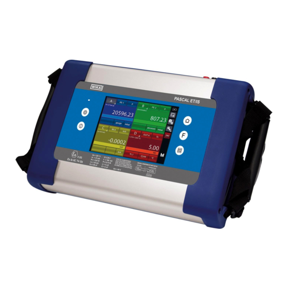
Multichannel Calibrator PASCAL ET, ET-P, ET/IS, ET-P/IS
GB
Documenting Multivariable Multichannel Calibrator PASCAL ET, ET-P, ET/IS, ET-P/IS
Table of
Contents
Previous
Page
Next
Page
1
2
3
4
5
Advertisement
Table of Contents
Need help?
Do you have a question about the PASCAL ET-P and is the answer not in the manual?
Ask a question
Questions and answers
Related Manuals for WIKA PASCAL ET-P
Test Equipment WIKA Pascal ET Operating Instructions Manual
Hand-held multifunction calibrator (148 pages)
Test Equipment WIKA PG28 Operating Instructions Manual
Bourdon tube pressure gauge, hastelloy (48 pages)
Test Equipment WIKA CPH6000 Operating Instructions Manual
Pressure calibrator (112 pages)
Test Equipment WIKA CPG1000 User Manual
Precision digital pressure gauge (7 pages)
Test Equipment WIKA CEP6000 Operating Instructions Manual
Hand-held multi-function calibrator (100 pages)
Test Equipment WIKA Mensor CPA8001 Operating Instructions Manual
Air data test set (114 pages)
Test Equipment WIKA CPH8000-ET Operating Instructions Manual
Hand-held multifunction calibrator (98 pages)
Test Equipment WIKA CPB3500 Operating Instructions Manual
Pneumatic dead-weight tester (84 pages)
Test Equipment WIKA PASCAL 100 Operating Instructions Manual
(88 pages)
Test Equipment WIKA CTD9100 series Operating Instructions Manual
Dry-well temperature calibrator, micro calibration bath, multi-function calibrator (148 pages)
Test Equipment WIKA CPH7650 Operating Instructions Manual
Portable pressure calibrator (144 pages)
Test Equipment WIKA GPU-10 Operating Instructions Manual
Sf6 service equipment (68 pages)
Test Equipment WIKA CPH7000 Manual
Portable process calibrator. (15 pages)
Test Equipment WIKA CPH6600 Operating Instructions Manual
Hand-held pressure calibrator with integrated pump (96 pages)
This manual is also suitable for:
Pascal et
Pascal et/is
Pascal et-p/is
Cph8000
Table of Contents
Print
Rename the bookmark
Delete bookmark?
Delete from my manuals?
Login
Sign In
OR
Sign in with Facebook
Sign in with Google
Upload manual
Upload from disk
Upload from URL


Need help?
Do you have a question about the PASCAL ET-P and is the answer not in the manual?
Questions and answers