SMC Networks PF3A703H Operation Manual
Digital flow switch
Hide thumbs
Also See for PF3A703H:
- Operation manual (99 pages) ,
- Operation manual (85 pages) ,
- Manual (48 pages)

Related Manuals for SMC Networks PF3A703H


Summary of Contents for SMC Networks PF3A703H
- Page 1 No.PF※※-OMU0002-D PRODUCT NAME Digital Flow Switch MODEL/ Series/ Product Number PF3A703H PF3A706H PF3A712H...
-
Page 2: Table Of Contents
Table of Contents Safety Instructions Model Indication and How to Order Names and Functions of Individual Parts Definition and terminology Mounting and Installation Installation Piping method Wiring Outline of Settings [Measurement mode] Change of Set Value [3 step setting mode] Default setting Change of Set Flow and Hysteresis [Simple setting mode] Change the Function Settings [Function selection mode]... -
Page 3: Safety Instructions
Safety Instructions These safety instructions are intended to prevent hazardous situations and/or equipment damage. These instructions indicate the level of potential hazard with the labels of "Caution", "Warning" or "Danger". They are all important notes for safety and must be followed in addition to International Standards (ISO/IEC) , and other safety regulations. - Page 4 Safety Instructions Caution 1.The product is provided for use in manufacturing industries. The product herein described is basically provided for peaceful use in manufacturing industries. If considering using the product in other industries, consult SMC beforehand and exchange specifications or a contract if necessary. If anything is unclear, contact your nearest sales branch.
- Page 5 ■Operator ♦This Operation Manual is intended for those who have knowledge of machinery using pneumatic equipment, and have sufficient knowledge of assembly, operation and maintenance of such equipment. Only those persons are allowed to perform assembly, operation and maintenance. ♦Read and understand this Operation Manual carefully before assembling, operating or providing maintenance to the product.
- Page 6 Caution ■Do not touch the terminals and connectors while the power is on. Otherwise electric shock, malfunction and damage to the product can result. ■After maintenance is complete, perform appropriate functional inspections and leak test. Stop operation if the equipment does not function properly or there is leakage of fluid. When leakage occurs from parts other than the piping, the product itself may be damaged.
- Page 7 ●Product handling Mounting •Tighten to the specified tightening torque. If the tightening torque is exceeded, the product can be damaged. Insufficient torque can cause displacement of the product from its proper position and the looseness of the mounting screws. •If a commercially available switching power supply is used, be sure to ground the frame ground (FG) terminal.
- Page 8 Wiring (Including connecting/ disconnecting of the connectors) •Do not pull hard on the lead wire. Especially never lift the product equipped with fitting and piping by holding the lead wires. Damage to the connector, circuit board, cover or internal components may result, causing failure or malfunction. •Avoid repeatedly bending, stretching or applying a heavy object or force to the lead wire.
- Page 9 Operating environment •Do not use the product in an environment where the product is constantly exposed to water splashes. Otherwise failure or malfunction can result. Take measures such as using a cover. •Do not use the product in an environment where corrosive gases or fluids can be splashed. Otherwise damage to the internal parts can result, causing malfunction.
- Page 10 Adjustment and Operation •Connect the load before turning the power supply on. •Do not short-circuit the load. Although error is displayed when the product load has a short circuit, generated over current may lead to the damage of the product. •Do not press the setting buttons with a sharp pointed object.
-
Page 11: Model Indication And How To Order
Model Indication and How to Order Accessories/ Part numbers If an accessory is required, order using the following part number. Product number Description Note ZS-37-A Lead wire with M12 connector Length: 3 m - 10 - No.PF※※-OMU0002-D... -
Page 12: Names And Functions Of Individual Parts
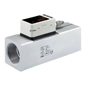
Names and Functions of Individual Parts Body Connector pin numbers (on the product) DC(+) FUNC DC(-) Element Description Display See below Connector M12 4-pin connector for electrical connections. Lead wire with Lead wire for power supply and outputs. M12 connector Piping port For piping connections. -
Page 13: Definition And Terminology
■Definition and terminology Term Definition The total amount of fluid that has passed through the device. If an Accumulated flow instantaneous flow of 100 L/min lasts for 5 minutes, the accumulated flow will be 5 x 100 = 500 L. Accumulated flow external A function to reset the accumulated value to "0"... - Page 14 Terminology Definition Indicates the change in the display value and analogue output when the fluid Pressure characteristics pressure changes. Pressure limit that if exceeded will result in mechanical and/or electrical Proof pressure damage to the product. The flow range within which the product will meet all published Rated flow range specifications.
-
Page 15: Mounting And Installation
Mounting and Installation Mounting •Never mount the product in a place that will be used as a mechanical during piping. •Attach the piping so that the fluid flows in the direction indicated by the arrow on the body. •Never mount the product upside down. •The monitor with integrated display can be rotated. -
Page 16: Installation
•Install the product with 4 screws suitable for the product number according to the required tightening torque. Product number Suitable screws Tightening torque Thread depth 1.5 N•m ±10% PF3A703H Equivalent to M4 3 N•m ±10% PF3A706H Equivalent to M5 5.2 N•m ±10% PF3A712H Equivalent to M6 •Prepared by the user. -
Page 17: Piping Method
■Piping •Do not connect equipment or piping which may generate a fluctuation in flow or drift at the IN side of the product. When installing a regulator at the IN side of the product, make sure that hunting is not generated. •The piping on the IN side must have a straight section of piping whose length is 8 times the piping diameter or more. -
Page 18: Wiring
■Wiring Connection •Connections should only be made with the power supply turned off. •Use a separate route for the product wiring and any power or high voltage wiring. If wires and cables are routed together with power or high voltage cables, malfunction may result due to noise. •If a commercially available switching power supply is used, be sure to ground the frame ground (FG) terminal. - Page 19 Internal circuit and wiring examples NPN + Analogue output type PF3A7□□H-□□-CS/DS□-□□ Maximum applied voltage: 28 VDC Maximum load current: 80 mA Internal voltage drop 1 V max. CS: Analogue output: Select 1 to 5 V or 0 to 10 V. Output impedance: 1 k DS: Analogue output 4 to 20 mA Max.
- Page 20 NPN + Analogue output type PF3A7□□H-□□-ES/FS□-□□ Maximum load current: 80 mA Internal voltage drop 2 V max. ES: Analogue output: Select 1 to 5 V or 0 to 10 V Output impedance: 1 k FS: Analogue output 4 to 20 mA Max.
- Page 21 Example of wiring for accumulated pulse output PF3A7□□H-□□-CS/DS□-□□ PF3A7□□H-□□-ES/FS□-□□ - 20 - No.PF※※-OMU0002-D...
-
Page 22: Outline Of Settings [Measurement Mode]
Outline of Settings [Measurement mode] Power is supplied. The output will not operate for 3 seconds after supplying power. The identification code of the product is displayed. [Measurement mode] Measurement mode is the condition where the flow is detected and displayed, and the switch function is operating. -
Page 23: Change Of Set Value [3 Step Setting Mode]
When the flow exceeds the set value [P], the switch will be turned ON. When the flow falls below the set value by the amount of hysteresis [H] or more, the switch will turn OFF. If the operation shown below is acceptable, then keep these settings. ●PF3A703H Item Default Settings... - Page 24 <Operation> [Hysteresis mode] In the 3 step setting mode, the set value (P or n) and hysteresis (H) can be changed. Set the items on the sub display (set value and hysteresis) using the ▲ or ▼ buttons. When changing the set value, follow the operation below. The hysteresis setting can be changed in the same way.
- Page 25 [Window comparator mode] The Flow switch turns on within a set flow range (from PL to PH). Set PL, the lower limit of the switch operation, and PH, the upper limit of the switch operation and WH (hysteresis) following the instructions given above.
-
Page 26: Change Of Set Flow And Hysteresis [Simple Setting Mode]
Change of Set Flow and Hysteresis [Simple setting mode] ■Simple setting mode In the simple setting mode, the set value, hysteresis and delay time can be changed while checking the current flow value (main display). <Operation> [Hysteresis mode] (1) Press the S button for 1 second or longer (but less than 3 seconds) in measurement mode. [SEt] is displayed on the main display. - Page 27 [Window comparator mode] Set PL, the lower limit of the switch operation, and PH, the upper limit of the switch operation, and WH (hysteresis) following the instructions given above. (refer to setting method on page 25) (When reversed output is selected, the main screen displays nL and nH.) [Accumulated output mode] Set each P (set value), referring to the Setting method on page 25.
-
Page 28: Change The Function Settings [Function Selection Mode]
Change the Function Settings [Function selection mode] ■Function selection mode In this mode, each function setting can be changed separately. In measurement mode, press the S button for 3 seconds or longer to display [F 0]. Press the ▲ or ▼ button to select the function to be changed. Press the S button for 2 seconds or longer to return to measurement mode. -
Page 29: Default Setting
L] L/min oUt] Select output mode [ HyS] Hysteresis mode ot] Select switch mode P] Normal output [ 1500] 1500 L/min (PF3A703H) P] Select input switch operation [ 3000] 3000 L/min (PF3A706H) [ 6000] 6000 L/min (PF3A712H) [F 1] Page... -
Page 30: F0 Reference Condition/ Units Selection Function
■[F 0] Reference condition/ Units selection function Reference condition Standard condition or normal condition can be selected. Standard condition and normal condition are defined as follows: •Standard condition: Displayed flow rate which is converted to volume at 20°C, 101.3 kPa (absolute pressure). •Normal condition: Displayed flow rate which is converted to volume at 0°C, 101.3 kPa (absolute pressure). - Page 31 Flow specification when [ Ft] is selected by the units selection function Models PF3A703H PF3A706H PF3A712H Rated flow range 1.1 to 105.9 cfm 2.2 to 211.9 cfm 4.5 to 423.8 cfm Instantaneous flow 1.1 to 111.2 cfm 2.2 to 222.6 cfm 4.5 to 445.0 cfm...
-
Page 32: F1 Setting Of Out
■[F 1] Setting of OUT Set the output mode of OUT. ●Switch output modes Select the output mode required from the table below. Normal output Reversed output Hysteresis mode Window comparator mode Accumulated output mode (Increment) Accumulated output mode (Decrement) Accumulated pulse output mode... - Page 33 ●Flow setting chart Refer to the list of switch output modes for the setting procedure. Mark the procedure path with a pen or a marker. Enter the items you selected, following the procedure below. - 32 - No.PF※※-OMU0002-D...
- Page 34 Follow the setting flow chart. <Operation> Display [F_1] by pressing ▲ or ▼ button in function selection mode. Press the S button. Move on to select output mode. Select output mode Press the ▲ or ▼ button to select the output mode. Move on to select normal output/ Press the S button to set.
- Page 35 Select display colour Press the ▲ or ▼ button to select the display colour. Press the S button. Return to function selection mode. [F 1] Setting of OUT completed. : Selected item becomes valid after pressing S button. : After enabling the setting by pressing S button, it is possible to return to the measurement mode by keeping pressing S button. - 34 - No.PF※※-OMU0002-D...
- Page 36 a. When hysteresis mode is selected Input of set value Set the flow based on the setting method on page 31. The snap shot function can be used. (Refer to page 60) Press the S button to set. Move on to setting of hysteresis. Setting of Hysteresis Set the flow based on the setting method on page 31.
- Page 37 b. When window comparator output mode is selected Input of set value (Lower limit value) Set the flow based on the setting method on page 31. The snap shot function can be used. (Refer to page 60) Press the S button to set. Move on to input of set value (upper limit value).
- Page 38 c. When Accumulated output mode is selected Select accumulated output increment (addition)/ decrement (subtraction) Press the ▲ or ▼ button to select the accumulated increment/ decrement. Press the S button to set. Move on to input the set value (upper 6 digits). The accumulated output can be set between 0 and 999,999,999,990 L.
- Page 39 Input of set value (lower 6 digits) All of the values will flash. Press the ▲ or ▼ button to change the value. Press the S button to move on to the digit to the right. Press the S button for 1 second or longer to flash all the values. (Press the S button while all the digits are flashing to move to the setting of the display colour.
- Page 40 d. When accumulated pulse output mode is selected Select accumulated pulse output Press the ▲ or ▼ button to select accumulated pulse output. Press the S button to set. Move on to select display colour. Select display colour (Refer to select display colour of page 34.) : When the accumulated pulse output mode is selected, the output operation indicator LED will turn off.
-
Page 41: F3 Response Time
■[F 3] Response time setting The response time of the switch output and analogue output can be selected. Output chattering can be prevented by setting the response time. <Operation> Display [F_3] by pressing ▲ or ▼ button in function selection mode. Press the S button. -
Page 42: F5 Func Setting
■[F 5] FUNC setting Analogue output or external input can be selected. •When analogue output is selected 1 to 5 V or 0 to 10 V can be selected when the analogue voltage output type is used. The flow value corresponding to 5 V (10 V) or 20 mA can be selected with the analogue output free range function. - Page 43 <Operation> Display [F_5] by pressing ▲ or ▼ button in function selection mode. Press the S button. Move on to select FUNC. Select FUNC Press the ▲ or ▼ button to select the FUNC setting. [ oUt] Analogue output is [ oUt] Analogue output is [in] External input is selected...
- Page 44 Select analogue output free range function Press the ▲ or ▼ button to select analogue output free setting function. [on] Free range function [oFF] Free range function ON is selected OFF is selected. Press the S button to set Press the S button to return value input.
-
Page 45: F10 Sub Display Setting (Line Name Setting)
■[F10] Sub display setting (Line name setting) Add the displayed item to the sub display. •Default setting: Accumulated value, OUT setting, peak value, and bottom value are displayed. •Addition of line name: Line name can be added to the default display. A line name can be input. -
Page 46: F13 Setting For Reverse Display Mode
■[F13] Setting for reverse display mode This function is used to rotate display upside down. It is used to correct the display when it is upside down due to installation of the product. When the reverse display function is ON, the function of the ▲/▼ buttons are reversed. <Operation>... -
Page 47: F14 Zero Cut-Off Setting
Press the ▲ or ▼ button to select the value of Zero cut-off. : The display above is an example of when [L] is selected for the PF3A703H(3000 L/min type) with the unit switching function. : If the flow rate does not reach the above value, the display will be zero. - Page 48 ●Settable flow range when [L] is selected by the units selection function Displayable flow range Zero cut-off Zero cut-off set value range PF3A703H PF3A706H PF3A712H 0%F.S. 0 to 3150 L/min 0 to 6300 L/min 0 to 12600 L/min 30 to 3150 L/min...
- Page 49 ●Flow specification when [Ft] is selected by the units selection function. Set point range Zero cut-off Zero cut-off set value range PF3A703H PF3A706H PF3A712H 0 to 111.2 cfm 0 to 222.6 cfm 0 to 445.0 cfm 0%F.S. 1.1 to 111.2 cfm 2.2 to 222.6 cfm...
- Page 50 However, please note that the set value and hysteresis of the switch output will not be changed. To maintain the on-off point, set the value and hysteresis without the zero cut-off range. <Example: PF3A703H (3000 L/min type> Common setting Output mode...
-
Page 51: F30 Setting Of Accumulated Value Holding Time
■[F30] Setting of accumulated value hold In the default setting, the accumulated flow value is not held when the power supply is turned off. This function enables the accumulated flow value to be stored in permanent memory every 2 or 5 minutes. : When using the accumulated value hold function, calculate the product life from the operating conditions, and use the product within its life. -
Page 52: F80 Set Display Off Mode
■[F80] Set display OFF mode This function will turn the display OFF if no buttons are pressed for 30 seconds. However when a flow monitor (PFG3 series) is connected, the displayed value might be different, due to an error. When the flow monitor display is used, it is recommended to set this product to the display OFF mode. -
Page 53: F81 Security Code
■[F81] Security code The security code can be turned on and off and the security code can be changed when unlocked. < Operation > Display [F81] by pressing ▲ or ▼ button in function selection mode. Press the S button. Move on to Setting of security code Setting of Security code Press the▲... - Page 54 Changing of security code. New security code is displayed on the main display. Press the ▲ or ▼ button to change the value. Press the S button to move on to input the next digit. After entry, the changed security code will flash by pressing the S button for 1 second or longer.
-
Page 55: F90 Setting Of All Functions
■[F90] Setting of all functions Each time the S button is pressed, the function steps in the order shown in the following table. <Operation> Display [F90] by pressing ▲ or ▼ button in function selection mode. Press the S button. Move on to the suction signal input check. - Page 56 Order of function settings Order Function Applicable model Reference condition All models [F 0] Unit selection function Model with units selection function OUT output mode All models All models OUT switch operation (When setting mode is selected, except output off mode) All models [F 1] OUT set value...
-
Page 57: F96 Check Of Input Signal
■[F96] Check of input signal When the external input is selected by the FUNC setting, the ON/OFF of the input signal can be checked. : However when analogue output is selected, the ON/OFF of the input signal cannot be checked. <Operation>... -
Page 58: F98 Setting Of Output Check
■[F98] Setting of output check The operation of the output can be checked by switching the output ON/OFF by pressing a button, without the need for a flow of fluid. < Operation > Display [F98] by pressing ▲ or ▼ button in function selection mode. Press the S button. - Page 59 Analogue output check Press the ▲ or ▼button to select analogue output check. 0 V or 4 mA is output when [Lo], and 5 V (0 V) or 20 mA is output when [Hi]. : ( ) is an output value when 0 to 10 V is selected. Return to function selection Press the S button to set.
-
Page 60: F99 Reset To The Default Settings
■[F99] Reset to the default settings If the Flow switch settings are uncertain, the default values can be restored. <Operation> Display [F99] by pressing ▲ or ▼ button in function selection mode. Press the S button. Move on to reset to factory default settings. Rest to factory default settings. -
Page 61: Other Settings
Other Settings ●Reset operation The Accumulated Flow, Peak Value and Bottom Value can be reset. To reset the accumulated value, press the ▼ and S button for 1 second or longer. ●Snap shot function The current flow rate value can be stored to the switch output ON/OFF set point. When the items on the Sub display (left) are selected in either 3 step setting mode, Simple setting mode or Setting of each function mode, by pressing the ▲... - Page 62 ●Key-lock function The key lock function is used to prevent errors occurring due to unintentional changes of the set values. If S button is pressed while the keys are locked, [LoC] is displayed on the sub display (left) for approximately 1 second.
- Page 63 <Operation – Without security code input> •Locking (1) Press the S button for 5 seconds or longer in measurement mode. When [oPE] is displayed on the main display, release the button. The current setting [LoC] or [UnLoC] will be displayed on the sub display. (2) Select the key locking/ un-locking with ▲...
-
Page 64: Maintenance
Maintenance How to reset the product after a power loss or when the power has been unexpectedly removed The settings for the product are retained in memory prior to the power loss or de-energizing of the product. The output condition is also recoverable to that prior to the power loss or de-energizing. However, this may change depending on the operating environment. -
Page 65: Troubleshooting
Troubleshooting If an operation failure of the product occurs, please confirm the cause of the troubles from the following table. If a cause applicable to the troubles cannot be identified and normal operation can be recovered by replacement with a new product, this indicates that the product itself was faulty. Problems with the product may be due to the operating environment (installation etc). - Page 66 Problem Possible Error indication Investigation method Countermeasure causes (1) Check if the output current is 80 mA or greater. (1)(2) Connect the appropriate (2) Check if the connected load load. complies with the specification. (3) Use a relay with a surge Excess current Check if the load is short circuited.
- Page 67 Problem Possible Error indication Investigation method Countermeasure causes Incorrect power Check if the power supply voltage is Power supply voltage is 24 VDC supply 24 VDC ±10%. ±10%. Check the power supply wiring The display turns Check if the brown and blue wires are off.
- Page 68 Problem Possible Error indication Investigation method Countermeasure causes Key-lock mode is Check if the key-lock function is turned Check the key-lock function. Buttons do not activated. work Product failure Replace the product Rework the piping. If the tightening torque is Air leakage Check if air is leaking from the piping.
-
Page 69: Error Display
■Error display Error name Error display Description Measures Instantaneous flow Flow rate exceeding the upper limit Reset applied flow rate to a level within error of the settable flow range is applied. the settable flow range. Turn the power off and remove the The switch output load current is Over current error cause of the over current. -
Page 70: Specifications
Specifications Models PF3A703H PF3A706H PF3A712H 1 Applicable fluid Air, N Fluid Operating fluid temperature 0 to 50 Detection method Heating type sensor Rated flow range 30 to 3000 L/min 60 to 6000 L/min 120 to 12000 L/min Instantaneous 30 to 3150 L/min... - Page 71 Models PF3A703H PF3A706H PF3A712H 7 Voltage output: 1 to 5 V (0 to 10 V can also be selected Output type Current output: 4 to 20 mA Output Output impedance approx. 1 kΩ Analogue voltage 6 output Impedance Current Max. load impedance 600 Ω...
- Page 72 1: The air quality class is according to JIS B 8392-1:2012 [3:6:-] and ISO8573-1:2010 [3:6:-]. 2: When using the accumulated value hold function, calculate the product life from the operating conditions, and use the product within its life. Maximum updating time of accumulated value is 1.5 million times. If the product is energized for 24 hours per day, the product life will be as follows: •Data memorized every 5 minutes --- 5 minutes x 1.5 million times = 7.5 million minutes = 14.3 years •Data memorized every 2 minutes --- 2 minutes x 1.5 million times = 3 million minutes = 5.7 years...
-
Page 73: Characteristics Data
(0 to 10 V) 1 Current output 4 mA 4.16 mA 20 mA Models Minimum value of rated flow range Maximum value of rated flow range PF3A703H 30 L/min 3000 L/min PF3A706H 60 L/min 6000 L/min PF3A712H 120 L/min 12000 L/min 1: Analogue output accuracy is within ±3%F.S. - Page 74 ●Pressure loss (reference value) •PF3A703H (For 3000 L/min) •PF3A706H (For 6000 L/min) •PF3A712H (For 12000 L/min) - 73 - No.PF※※-OMU0002-D...
- Page 75 If a straight section of piping is not installed, the accuracy varies by approximately ±3% or more. : "Straight section" means a part of the piping without any bends or rapid changes in the cross sectional area. •PF3A703H (For 3000 L/min) •PF3A706H (For 6000 L/min) •PF3A712H (For 12000 L/min)
-
Page 76: Dimensions
■Dimensions Symbol Models PF3A703H 79.1 55.3 22.5 4 x M4 x 0.7 depth 7 PF3A706H 94.1 70.3 4 x M5 x 0.8 depth 8 PF3A712H 104.1 80.3 4 x M6 x 1.0 depth 9 - 75 - No.PF※※-OMU0002-D... - Page 77 Lead wire with M12 connector (ZS-37-A) Pin number Description Colour DC(+) Brown FUNC White DC(-) Blue Black : 4-wire lead wire with M12 connector for PF3A series. - 76 - No.PF※※-OMU0002-D...
- Page 78 Revision history A: Modified errors in text. [October 2017] B: Contents revised in several places. [July 2018] C: Contents revised in several places. [August 2019] D: Contents revised in several places. [August 2022] 4-14-1, Sotokanda, Chiyoda-ku, Tokyo 101-0021 JAPAN Tel: + 81 3 5207 8249 Fax: +81 3 5298 5362 https://www.smcworld.com Note: Specifications are subject to change without prior notice and any obligation on the part of the manufacturer.
Need help?
Do you have a question about the PF3A703H and is the answer not in the manual?
Questions and answers