Table of Contents
Advertisement
Available languages
Available languages
Quick Links
HAUSTECHNIK
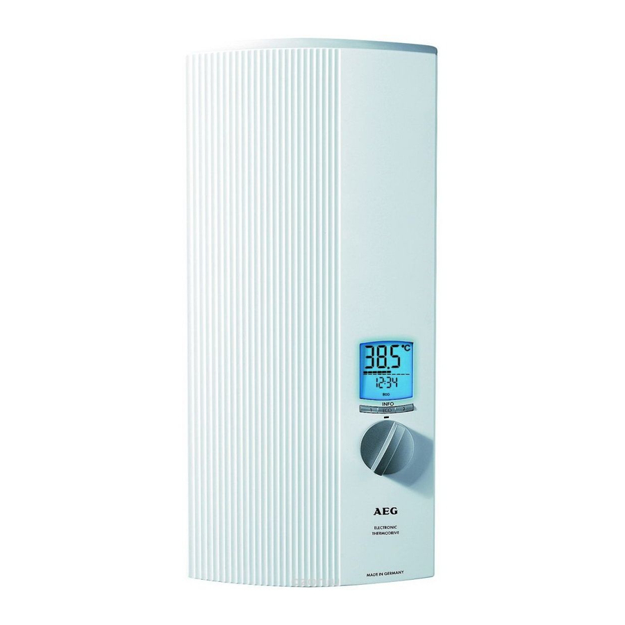
DDLE ÖKO TD 18
DDLE ÖKO TD 18/21/24
DDLE ÖKO TD 27
Vollelektronisch geregelter Komfort-Durchlauferhitzer
Bedienung und Installation _________________________________ 2
Fully electronically controlled comfort instantaneous water
heater
Operation and installation ________________________________ 22
Advertisement
Chapters
Table of Contents

Related Manuals for AEG DDLE ÖKO TD 18


Summary of Contents for AEG DDLE ÖKO TD 18
- Page 1 HAUSTECHNIK DDLE ÖKO TD 18 DDLE ÖKO TD 18/21/24 DDLE ÖKO TD 27 Vollelektronisch geregelter Komfort-Durchlauferhitzer Bedienung und Installation _________________________________ 2 Fully electronically controlled comfort instantaneous water heater Operation and installation ________________________________ 22...
-
Page 2: Table Of Contents
Inhalt - Besondere Hinweise BESONDERE HINWEISE UMWELT UND RECYCLING BEDIENUNG KUNDENDIENST UND GARANTIE Allgemeine Hinweise ........... 3 Sicherheit ..............3 Gerätebeschreibung ........... 4 Bedienung ..............5 Wartung und Pflege............. 8 Was tun, wenn ............. 8 INSTALLATION Sicherheit ..............10 Gerätebeschreibung .......... -
Page 3: Allgemeine Hinweise
Bedienung BEDIENUNG 1.3 Maßeinheiten Hinweis Wenn nicht anders angegeben, sind alle Maße in Millimeter. 1. Allgemeine Hinweise 2. Sicherheit Die Kapitel „Besondere Hinweise“ und „Bedienung“ rich- ten sich an den Gerätebenutzer und den Fachhandwerker. 2.1 Bestimmungsgemäße Verwendung Das Kapitel „Installation“ richtet sich an den Fachhand- werker. -
Page 4: Gerätebeschreibung
Bedienung INFO-Menü WARNUNG Verletzung Durch Drücken der ECO-Taste gelangen Sie in das IN- Das Gerät kann von Kindern ab 3 Jahren sowie von FO-Menü und können so Komfortfunktionen individuell Personen mit verringerten physischen, sensori- einstellen und/oder Werte abfragen (siehe Kapitel „ECO schen oder mentalen Fähigkeiten oder Mangel an wählen“): Einstellen der ECO-Temperaturen/Durchfluss- Erfahrung und Wissen benutzt werden, wenn sie... -
Page 5: Bedienung
Bedienung Display-Hintergrundbeleuchtung Zweite Zeile im Display Das Display im Gerät ist mit einer Hintergrundbeleuch- Sie können wählen, welche weitere Information in der tung ausgestattet. Wenn Sie Temperaturen bis 42,5 °C zweiten Zeile des Displays angezeigt werden soll (siehe einstellen, leuchtet die Hintergrundbeleuchtung blau, bei Kapitel „Einstellungen im INFO-Menü“): Temperaturen ab 43,0 °C wechselt das Display seine l/min... - Page 6 Bedienung 4.1.1 Temperatur einstellen Bedienung Anzeige im Display » Temperatur wählen 30 ... 60 °C, stufenlose Einstell- Zum Beispiel 43 °C. möglichkeit. OFF = Heizung ausgeschaltet. 4.1.2 Speichertasten belegen » Wunsch-Temperatur 30 ... 60 °C zum Speichern Zum Beispiel 38 °C. einstellen.
- Page 7 Bedienung 4.2.5 Kindersicherung einschalten / ausschalten / einstellen » ECO drei Sekunden drücken. 38 °C » ECO mehrmals kurz drücken. » "OFF" / "On" wählen. OFF: ausgeschaltet. On: eingeschaltet. » ECO kurz drücken. 43 °C » Temperatur einstellen. Zum Beispiel 36 °C.
-
Page 8: Wartung Und Pflege
Bedienung 4.2.10 Temperaturfunktaster - Abfrage / - Anmeldung / - Abmeldung Temperaturfunktaster - Abfrage am Gerät » ECO drei Sekunden drücken. 38 °C » ECO mehrmals kurz drücken. rc 1 ... 4 Zahl der angemeldeten Temperaturfunktaster (rc: re- mote control). Temperaturfunktaster - Anmeldung zum Gerät vornehmen »... - Page 9 Bedienung » Entnehmen Sie die bisherige Batterie und schieben die neue Batterie Typ CR 2032 ein. Hinweis Der Pluspol der Batterie muss von der Platine ab- gewandt sein. » Verschließen Sie das Gehäuse. Dabei achten Sie auf die Aussparung im Deckelrand. Durch die Aus- sparung wird die richtige Lage des Deckels bestimmt und die Abdichtung des Gehäuses gewährleistet.
-
Page 10: Installation
Installation INSTALLATION Wasserinstallation ◦ Kaltwasserleitung Zugelassene Werkstoffe: Feuerverzinktes Stahlrohr, Edelstahlrohr, Kupferrohr oder Kunststoffrohr. ◦ Warmwasserleitung 7. Sicherheit Zugelassene Werkstoffe: Edelstahlrohr, Kupferrohr oder Kunststoffrohr. Vorschriften und Bestimmungen ◦ Beim Betrieb können Betriebstemperaturen bis max. 65 °C erreicht werden. Im Störfall können in der In- ◦... -
Page 11: Gerätebeschreibung
Installation 8. Gerätebeschreibung Das Blankdraht-Heizsystem ist für kalkarme und kalkhal- tige Wässer geeignet (siehe Kapitel „Einsatzberei che“). Geräteaufbau 38° 55° Einstellknopf mit Tasten und Anzeigefeld Sicherheits-Temperaturbegrenzer (STB) mit Rücksetztaste Gerätekappe Heizsystem Rückwand-Unterteil Durchflusssensor Warmwasser-Schraubanschluss Stecker vom Temperatureinsteller zum „T-soll“ Kaltwasser-Schraubanschluss Typenschild Rückwand-Oberteil Aufhängeleiste... - Page 12 Installation 8.2 Lieferumfang 8.3.4 Verbrühschutz / Temperaturbegrenzung Menü Code Bedeutung Siehe Bild „Geräteaufbau“. Verbrühschutz / Temperaturbegrenzung aus- geschaltet. 8.3 Kundendienst-Modus Verbrühschutz / Temperaturbegrenzung einge- Den Kundendienst-Modus aktivieren / deaktivieren Sie schaltet. durch Drücken der SERVICE-Taste (1) auf der Rück- 31 ... 60 °C Bei On - Einstellung wählbare Maximal-Wert seite des Bedienfeldes (Verbindung zum „T-soll“...
-
Page 13: Montage
Installation 9.2 Gerätemontage vorbereiten Rohrbausatz Gas-Wasserheizer-Austausch Universal Montagerahmen (Technische Beschreibung 9.2.1 Gerät öffnen siehe Universal Montagerahmen) und Rohrbögen für eine Installation bei vorhandenen Gas-Wasserheizer-An- » Entriegeln Sie den Rastverschluss mithilfe eines schlüssen (Kaltwasseranschluss links und Warmwasse- Schraubendrehers (1). ranschluss rechts). »... - Page 14 Installation 9.2.8 Rückwand vorbereiten » Brechen Sie die Sollbruchstelle für die Kabeltülle in der Rückwand aus. Das Gerät können Sie unten mit zwei zusätzlichen Schrauben befestigen. Dies fordern wir, wenn Sie das Gerät mit auf dem Putz liegenden Wasseranschlüssen (Aufputzinstallation) montieren. Haben Sie versehentlich ein falsches Loch für die Kabel- 9.2.5 Elektroanschlusskabel herrichten tülle ausgebrochen, müssen Sie eine neue Rückwand...
- Page 15 Installation 9.2.11 Elektroanschluss herstellen » Drücken Sie die Rückwand fest und wandbündig an und verriegeln Sie diese mit dem Befestigungskne- » Schließen Sie das Elektroanschlusskabel an bel (5). die Netzanschlussklemme an (siehe Kapitel „Elektroschaltplan“). 9.3.2 Elektroanschluss – AP WARNUNG Stromschlag »...
-
Page 16: Erstinbetriebnahme
Installation 9.3.4 Untertischmontage Wasseranschlüsse - oben 9.3.6 Montage Temperaturfunktaster Eine Untertisch-Gerätemontage mit obenliegenden Was- Der Sender kann mithilfe der Wandhalterung an der Wand seranschlüssen können Sie mit dem zusätzlichen Rohr- befestigt werden. Die Wandhalterung kann mit dem beilie- bausatz-Untertischgeräte durchführen. Brechen Sie dazu genden Klebepad oder einer geeigneten Senkkopfschrau- die Öffnungen in der Rückwand für die Wasserrohre sau- be Ø... -
Page 17: Störungsbeseitigung
Installation 10.2 Verbrühschutz / Störung Ursache Behebung Hintergrundbe- Keine Netzspan- Prüfen Sie die Sicherun- Temperaturbegrenzung leuchtung im Be- nung. gen in der Hausinstalla- Eine gewünschte Temperaturbegrenzung können Sie im dienteil ist komplett tion. Kundendienst-Modus im Bereich von 31 ... 60 °C ein- aus. -
Page 18: Technische Daten
Installation 13.2 Elektroschaltplan Sieb reinigen 3/PE ~ 380 - 415 V Im Kaltwasser-Schraubanschluss befindet sich ein Sieb. Bei Verschmutzung können Sie dieses Sieb ausbauen und reinigen und anschließend wieder einbauen. 12.1 Batterieentsorgung Korrekte Entsorgung. Entsorgen Sie Akkus niemals in den Hausmüll. Entsor- gen Sie die Batterien bei Ihrem Händler oder über einer zentralen Recycling-Stelle für Sonderabfälle. - Page 19 Produktdatenblatt: Konventionelle Warmwasserbereiter nach Verordnung (EU) Nr. 812/2013 | 814/2013 DDLE ÖKO TD 18 DDLE ÖKO TD 18/21/24 DDLE ÖKO TD 27 222396 222398 222399 Hersteller AEG Haustechnik AEG Haustechnik AEG Haustechnik Lastprofil Energieeffizienzklasse Energetischer Wirkungsgrad Jährlicher Stromverbrauch Temperatureinstellung ab Werk °C...
- Page 20 Installation - Umwelt und Recycling DDLE ÖKO TD 18 DDLE ÖKO TD 18/21/24 DDLE ÖKO TD 27 Werte Max. zulässige Zulauftemperatur °C l/min >2,5 >2,5 >2,5 Druckverlust bei Volumenstrom 0,08 0,08/0,1/0,13 0,16 Volumenstrom für Druckverlust l/min 5,2/6,0/6,9 Warmwasserdarbietung l/min 9,9/11,6/13,2 14,9 Δϑ...
- Page 21 Kundendienst und Garantie Erreichbarkeit Soweit der Kunde wegen des Garantiefalles aufgrund gesetzli- cher Gewährleistungsansprüche gegen andere Vertragspartner Sollte einmal eine Störung an einem unserer Produkte auftre- Leistungen erhalten hat, entfällt eine Leistungspflicht von uns. ten, stehen wir Ihnen natürlich mit Rat und Tat zur Seite. Soweit eine Garantieleistung erbracht wird, übernehmen wir EHT Haustechnik GmbH keine Haftung für die Beschädigung eines Gerätes durch Dieb-...
- Page 22 Contents - Special information SPECIAL INFORMATION GUARANTEE OPERATION ENVIRONMENT AND RECYCLING General information ..........23 Safety ................23 Appliance description ..........24 Operation ..............25 Maintenance and care ..........28 What to do if .............. 28 INSTALLATION Safety ................29 Appliance description ..........
-
Page 23: General Information
Operation OPERATION 1.3 Units of measurement Note All measurements are given in mm unless stated otherwise. 1. General information 2. Safety The chapters "Special information" and "Operation" are intended for both users and qualified contractors. 2.1 Intended use The chapter "Installation" is intended for qualified con- tractors. -
Page 24: Appliance Description
Operation Where children or persons with limited physical, sensory Remote control via remote temperature control or mental abilities are allowed to use this appliance, we You can regulate this appliance via a remote tempera- recommend a permanent temperature limit. A qualified ture control. -
Page 25: Operation
Operation Second line of display Anti-scalding protection You can select what other information should be shown Your qualified contractor can set a permanent tempera- on the second line of the display (see chapter "Settings ture limit (see chapter "Customer service mode") to pre- in the INFO menu"): vent any water being drawn from the appliance at tem- peratures that could lead to a risk of injury. - Page 26 Operation 4.1.3 Calling up memory buttons » Hold down button 1 or 2. For example 38 °C and 43 °C. 4.1.4 Selecting / deselecting ECO » Press ECO: Selecting ECO , green LED illuminates. » Press ECO: Deselecting ECO , LED does not light up. 4.2 Settings in the INFO menu Accessing the menu Operation...
- Page 27 Operation 4.2.6 Switching Wellness comfort function on/off » Press ECO for three seconds. 38 °C » Briefly press ECO several times. » Select "OFF" / "ON". switched OFF: switched 4.2.7 Switching automatic water volume control on/off; setting » Press ECO for three seconds. 38 °C »...
-
Page 28: Maintenance And Care
Operation 4.3 Resetting to factory defaults » Press button 1 and button 2 simultaneously for two Display flashes to confirm. seconds. Anti-scalding protection and self-learning remote temperature control are not reset. Factory defaults (see chapter "Specification"). 4.4 Remote temperature control operation Remote temperature control operation »... -
Page 29: Installation
Installation INSTALLATION ◦ Never use taps/valves for open vented appliances. ◦ If you are using thermostatic valves, observe chapter Recommended settings. Note The appliance is suitable for preheated water up to 7. Safety 65 °C. The maximum permissible inlet temperature is 65 °C. Instructions and regulations Higher temperatures may damage the appliance. -
Page 30: Appliance Description
Installation 8. Appliance description The bare wire heating system is suitable for hard and soft water areas (see chapter "Application areas"). Unit layout 38° 55° Rotary selector with buttons and display High limit safety cut-out with reset button Appliance cover Heating system Lower back panel section Flow rate sensor... - Page 31 Installation 8.2 Standard delivery CAUTION Burns See Fig. "Appliance layout". If operating the appliance with preheated water, the set temperature limit and anti-scalding protection 8.3 Customer service mode may be ineffective. In such cases, limit the temperature at the upstream You can enable/disable customer service mode by press- central thermostatic valve;...
-
Page 32: Installation
Installation 9.2.2 Information regarding the appliance with heater is operated via the load shedding relay prior to any other appliance. changeover connected load In its delivered condition the appliance is set to 21 kW. Central thermostatic valve When changing to a different output, carry out the fol- Use the thermostatic valve for central premixing when lowing steps: operating an instantaneous water heater with preheated... - Page 33 Installation » Seal in both twin nipples before fully inserting them. Insert both twin nipples into the wall plates. » Thoroughly flush the cold water supply line. Note Never use the shut-off valve in the cold water inlet to reduce the flow rate. 9.2.6 Fitting the cable grommet »...
- Page 34 Installation 9.3 Installation versions Note This type of connection changes the IP rating of the 9.3.1 Power supply – unfinished walls - from below appliance. » Change the type plate. Cross out "IP 25" and mark the box "IP 24". Use a ballpoint pen to do this.
-
Page 35: Initial Start-Up
Installation 10. Initial start-up 10.1 Appliance Commissioning must only be carried out by a heating contractor. 18 Nm 9.3.6 Remote temperature control installation The transmitter can be fitted to the wall with the wall mounting bracket. The wall mounting bracket can be se- cured to the wall with the adhesive tape supplied or with »... -
Page 36: Troubleshooting
Installation 10.4 Appliance handover Fault Cause Remedy Fault message is One phase has Check the fuses/MCBs in » Explain the appliance function to users and familiar- only shown when dropped out. your fuse box/distribution ise them with how it works. hot water is drawn. -
Page 37: Specification
Installation 13. Specification 13.3 DHW output The DHW output is subject to the power supply, the appli- 13.1 Dimensions and connections ance connected load and the cold water inlet temperature. The rated voltage and rated output can be found on the type plate. - Page 38 Product datasheet: Conventional water heaters to regulation (EU) no. 812/2013 | 814/2013 DDLE ÖKO TD 18 DDLE ÖKO TD 18/21/24 DDLE ÖKO TD 27 222396 222398 222399 Manufacturer AEG Haustechnik AEG Haustechnik AEG Haustechnik Load profile Energy efficiency class Energy conversion efficiency Annual power consumption Default temperature setting °C...
- Page 39 Installation - Guarantee - Environment and recycling 13.7 Data table DDLE ÖKO TD 18 DDLE ÖKO TD 18/21/24 DDLE ÖKO TD 27 222396 222398 222399 Electrical data Rated voltage Rated output 16.2 19.4 16.2/19/21.7 18/21/24 19.4/22.6/25.8 Rated current 24.7 27 27.6/29.5/33.3 29/31/35 30.1/32.2/36.3 37.1 Fuse protection...
- Page 40 4 < A M H C M N = i b e h g f > AEG is a registered trademark used under license from AB Electrolux (publ). Irrtum und technische Änderungen vorbehalten! | Subject to errors and technical changes! | Sous réserve d‘erreurs et de modifications techniques! | Onder voorbehoud van vergissingen en technische wijzigingen! | Salvo error o modificación técnica! | Rätt till misstag...
Need help?
Do you have a question about the DDLE ÖKO TD 18 and is the answer not in the manual?
Questions and answers