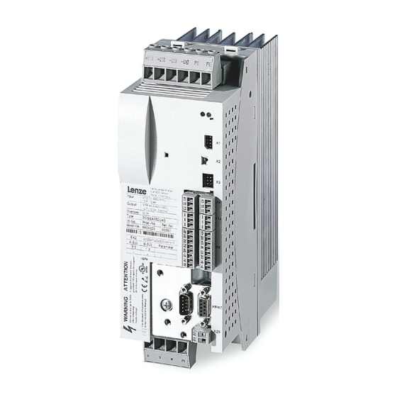
Lenze ECS Series Operating Instructions Manual
Axis module speed & torque
Hide thumbs
Also See for ECS Series:
- Operating instructions manual (483 pages) ,
- Mounting instructions (200 pages) ,
- Operating instructions manual (40 pages)

Related Manuals for Lenze ECS Series


Summary of Contents for Lenze ECS Series
- Page 1 EDBCSXS064 .LKn Operating Instructions ECSESxxx / ECSDSxxx / ECSCSxxx Axis module ˘ "Speed & Torque"...
- Page 2 0Fig. 0Tab. 0 © 2013 Lenze Automation GmbH, Hans−Lenze−Str. 1, D−31855 Aerzen No part of this documentation may be reproduced or made accessible to third parties without written consent by Lenze Automa- tion GmbH. All information given in this documentation has been selected carefully and complies with the hardware and software described.
- Page 3 ECSEA_003A EDBCSXS064 EN 4.0...
- Page 4 Scope of supply Position Description Quantity ECSLS... axis module Accessory kit with fixing material corresponding to the design (L): "E" − standard panel−mounted unit "D" − push−through technique "C" − cold−plate technique Mounting Instructions Drilling jig Functional earth conductor (only ECSDS...) Note! The ECSZA000X0B connector set must be ordered separately.
-
Page 5: Table Of Contents
............General safety and application notes for Lenze controllers . - Page 6 ........Entry of motor data for Lenze motors .
- Page 7 Contents Configuring the digital inputs and outputs ....... 6.9.1 Setting the polarity .
- Page 8 Contents Parameter setting ............General information .
- Page 9 Contents Monitoring functions ............Fault responses .
- Page 10 Contents Troubleshooting and fault elimination ........11.1 Fault analysis .
- Page 11 Contents 12.22 FCODE (free codes) ........... 12.23 FIXED (output of constant signals) .
-
Page 12: Preface And General Information
Preface and general information About these Operating Instructions Preface and general information About these Operating Instructions These Operating Instructions will assist you in connecting and commissioning the ECSxS... axis modules. They contain safety instructions which must be observed! All persons working on and with the ECSxS... axis modules must have the Operating Instructions available and must observe the information and notes relevant for their work. -
Page 13: Terminology Used
(PLC) or further controllers exclusively via the X4 interface. Interface X14 (CAN−AUX) is exclusively used for parameter setting and diagnostics. Drive PLC Developer Studio (Lenze software for PLC programming acc. to IEC 61131) Global Drive Control (Lenze software for parameter setting and diagnostics) -
Page 14: Code Descriptions
Preface and general information About these Operating Instructions Code descriptions 1.1.2 Code descriptions Lenze codes are described in the form of tables with the following structure: Column Abbreviation Meaning Cxxxx Code no. Cxxxx Subcode 1 of Cxxxx Subcode 2 of Cxxxx... -
Page 15: Signal Types And Scaling
About these Operating Instructions Signal types and scaling 1.1.3 Signal types and scaling A signal type can be assigned to most inputs and outputs of the Lenze function blocks/system blocks. The following signal types are distinguished: digital and analog signals ƒ... -
Page 16: Features Of The Ecsxs Axis Module
Interface X14 "CAN−AUX" for parameter setting and diagnostics Automation interface (AIF) ƒ – Connection to other fieldbus systems with Lenze communication modules (e.g. EMF2133IB PROFIBUS−DP) – Connection of the XT EMZ9371BC keypad for parameter setting and diagnostics Supported feedback systems: ƒ... -
Page 17: Scope Of Supply
Components for operation and communication ƒ Brake resistors ƒ Mains fuses ƒ Mains chokes ƒ RFI filters ƒ Tip! Information and auxiliary devices related to the Lenze products can be found in the download area at http://www.Lenze.com EDBCSXS064 EN 4.0... -
Page 18: Legal Regulations
Instructions. The specifications, processes, and circuitry described in these Instructions are for guidance only and must be adapted to your own specific application. Lenze does not take responsibility for the suitability of the process and circuit proposals. -
Page 19: Safety Instructions
Lenze Automation GmbH does not accept any liability for the suitability of the procedures and circuit proposals described. Depending on their degree of protection, some parts of the Lenze controllers ƒ (frequency inverters, servo inverters, DC speed controllers) and their accessory components can be live, moving and rotating during operation. - Page 20 Safety instructions General safety and application notes for Lenze controllers Application as directed Controllers are components which are designed for installation in electrical systems or machines. They are not to be used as domestic appliances, but only for industrial purposes according to EN 61000−3−2.
- Page 21 Reduce housing openings and cutouts to a minimum. Lenze controllers may cause a DC current in the PE conductor. If a residual current device (RCD) is used for protection against direct or indirect contact for a controller with three−phase supply, only a residual current device (RCD) of type B is permissible on the...
- Page 22 Safety instructions General safety and application notes for Lenze controllers Safety functions Certain controller versions support safety functions (e.g. "Safe torque off", formerly "Safe standstill") according to the requirements of the EC Directive 2006/42/EC (Machinery Directive). The notes on the integrated safety system provided in this documentation must be observed.
-
Page 23: Thermal Motor Monitoring
179 s in the event of a motor with a thermal motor time constant of 5 minutes (Lenze setting C0128), a motor current of 1.5 x I and a trigger threshold of 100 %. -
Page 24: Forced Ventilated Or Naturally Ventilated Motors
C0120 (OC6) or C0127 (OC8). Read release time in the diagram Diagram for detecting the release times for a motor with a thermal motor time constant of 5 minutes (Lenze setting C0128): L [%] = 1 × I = 3 ×... -
Page 25: Self−Ventilated Motors
C0129/x. Parameter setting The following codes can be set for I x t monitoring: Code Meaning Value range Lenze setting C0066 Display of the I x t load of the motor 0 ... 250 % − C0120 Threshold: Triggering of error "OC6"... - Page 26 Safety instructions Thermal motor monitoring Self−ventilated motors Calculate release time and I x t load Calculate the release time and the I x t load of the motor considering the values in C0129/1 and C0129/2(evaluation coefficient "y"). Formulae for release time Information Release time of the I x t monitoring...
-
Page 27: Residual Hazards
ECSxE supply module and the input current ƒ limitation is activated depending on the DC−bus voltage (C0175 = 1 or 2). the axis module is not supplied via a supply module delivered by Lenze. ƒ the low−voltage supply (24 V) is switched off. - Page 28 Motor protection Only use motors with a minimum insulation resistance of û = 1.5 kV, ƒ min. du/dt = 5 kV/ms. – Lenze motors meet these requirements. When using motors with an unknown insulation resistance, please contact your ƒ motor supplier.
-
Page 29: Safety Instructions For The Installation According To Ul
Safety instructions Safety instructions for the installation according to UL Safety instructions for the installation according to UL Warnings! General markings: Use 60/75 °C or 75 °C copper wire only. ƒ Maximum ambient temperature 55 °C, with reduced output current. ƒ... -
Page 30: Notes Used
Safety instructions Notes used Notes used The following pictographs and signal words are used in this documentation to indicate dangers and important information: Safety instructions Structure of safety instructions: Danger! (characterises the type and severity of danger) Note (describes the danger and gives information about how to prevent dangerous situations) Pictograph and signal word Meaning... -
Page 31: Technical Data
Technical data General data and operating conditions Technical data General data and operating conditions Standards and operating conditions Conformity Low−Voltage Directive (2006/95/EG) Approvals UL 508C Power Conversion Equipment Underwriter Laboratories (File No. E132659) CSA 22.2 No. 14 for USA and Canada Max. - Page 32 Technical data General data and operating conditions General electrical data Compliance with the requirements acc. to EN 61800−3 Noise emission Compliance with the limit class C2 acc. to EN 61800−3 (achieved by using collective filters typical for the application) Noise immunity Requirements acc.
-
Page 33: Rated Data
Technical data Rated data Rated data Axis module Rated data Type ECSxL004 ECSxL008 ECSxL016 Output power 400 V mains [kVA] rated Data for operation with upstream power supply module mains on mains voltage DC−bus voltage 15 ... 770 DC−bus DC−bus current DC−bus Rated output current at 4 kHz (causes a heatsink temperature of 70°C at an ambient... - Page 34 Technical data Rated data Rated data Type Axis module ECSxL032 ECSxL048 ECSxL064 Output power 400 V mains [kVA] 11.2 13.2 rated Data for operation with upstream power supply module mains on mains voltage DC−bus voltage 15 ... 770 DC−bus DC−bus current 15.6 12.5 20.9...
-
Page 35: Current Characteristics
Technical data Current characteristics Increased continuous current depending on the control factor Current characteristics 3.3.1 Increased continuous current depending on the control factor In the lower speed range ˘ the motor does not need the full motor voltage ˘ particularly the more powerful ECS axis modules can be permanently operated with increased output ^ 33). - Page 36 Technical data Current characteristics Increased continuous current depending on the control factor The following table shows the connections between mains voltage, DC−bus voltage and motor voltage: Mains voltage DC−bus voltage Output voltage (motor voltage) nominally achievable for 100 % x 1.35] mains mains modulation...
- Page 37 Technical data Current characteristics Increased continuous current depending on the control factor Example: The ECS axis module suitable for operation in conjunction with a Lenze motor of type MCS 14L32 is to be determined. Rated motor data ƒ – Rated motor torque (M ) = 17.2 Nm...
-
Page 38: Device Protection By Current Derating
Technical data Current characteristics Device protection by current derating 3.3.2 Device protection by current derating The maximum output current is limited. With output frequencies < 5 Hz the limitation depends on the heatsink temperature. ‚ 1.00 1.00 Iout ≤ 70 °C Imax ... -
Page 39: Mechanical Installation
– Ensure unimpeded ventilation of cooling air and outlet of exhaust air. – Several modules of the ECS series can be installed in the control cabinet next to each other without any clearance. The mounting plate of the control cabinet ƒ... -
Page 40: Mounting With Fixing Rails (Standard Installation)
Mechanical installation Mounting with fixing rails (standard installation) Dimensions Mounting with fixing rails (standard installation) 4.2.1 Dimensions Note! Mounting with ECSZS000X0B shield mounting kit: Mounting clearance below the module > 195 mm ƒ ECSxA005 Fig. 4−1 Dimensions for "panel−mounted" design Axis module Dimensions [mm] Type... -
Page 41: Mounting Steps
Mechanical installation Mounting with fixing rails (standard installation) Mounting steps 4.2.2 Mounting steps How to install the axis module: 1. Prepare the fixing holes on the mounting surface. – Use the drilling jig for this purpose. 2. Take the fixing rails from the accessory kit in the cardboard box. 3. -
Page 42: Mounting With Thermal Separation (Push−Through Technique)
Mechanical installation Mounting with thermal separation (push−through technique) Mounting with thermal separation (push−through technique) For the push−through technique the rear panel of the control cabinet must be a steel plate with a thickness of at least 2 mm. The edges of the mounting cutout and the fixing holes for the clamps must be slightly curved inwards (towards the axis module). -
Page 43: Dimensions
Mechanical installation Mounting with thermal separation (push−through technique) Dimensions 4.3.1 Dimensions Note! Mounting with ECSZS000X0B shield mounting kit: Mounting clearance below the module > 195 mm ƒ ECSXA007 Fig. 4−2 Dimensions for "push−through design" Mounting cutout (a1 x b1), ^ 44 Axis module Dimensions [mm] Type... - Page 44 Mechanical installation Mounting with thermal separation (push−through technique) Dimensions Dimensions of mounting cutout Note! Installation with shield mounting ECSZS000X0B: Clearance below the mounting cutout > 220 mm ƒ ECSXA063 Fig. 4−3 Dimensions of mounting cutout Mounting surface Mounting cutout for size 0 Mounting cutout for size 1 Axis module Dimensions [mm]...
-
Page 45: Mounting Steps
Mechanical installation Mounting with thermal separation (push−through technique) Mounting steps 4.3.2 Mounting steps How to mount the axis module: 1. Prepare the fixing holes for the wire clamps on the mounting area. For this purpose, apply a drilling jig. 2. Prepare the mounting cutout. The edges of the mounting cutout and the fixing holes for the wire clamps have to be slightly arched inwardly (to the axis module). -
Page 46: Mounting In Cold−Plate Design
Mechanical installation Mounting in cold−plate design Mounting in cold−plate design The axis modules ECSC... are intended for mounting in cold−plate design (e.g. on collective coolers). Requirements for collective coolers The following requirements must be met to ensure a safe operation of the axis modules: Good thermal contact with the cooler ƒ... -
Page 47: Dimensions
Mechanical installation Mounting in cold−plate design Dimensions 4.4.1 Dimensions Note! Mounting with ECSZS000X0B shield mounting kit: Mounting clearance below the module > 195 mm ƒ ECSXA009 Fig. 4−5 Dimensions for "cold−plate design" Axis module Dimensions [mm] Type Size ECSC ECSC 88,5 ECSC ECSC... -
Page 48: Mounting Steps
Mechanical installation Mounting in cold−plate design Mounting steps 4.4.2 Mounting steps À Á Â ECSXA030 Fig. 4−6 Mounting for "cold−plate design" Proceed as follows to mount the axis module: 1. Prepare the fixing holes on the mounting plate. – Use a drilling jig for this purpose. 2. -
Page 49: Electrical Installation
Electrical installation Installation according to EMC (installation of a CE−typical drive system) Electrical installation Installation according to EMC (installation of a CE−typical drive system) General information The electromagnetic compatibility of a machine depends on the type of installation ƒ and care taken.Especially consider the following: –... - Page 50 Electrical installation Installation according to EMC (installation of a CE−typical drive system) Assembly Connect the ECS modules, RFI filters, and mains choke to the earthed mounting ƒ plate with a surface as large as possible: – Mounting plates with conductive surfaces (zinc−coated or stainless steel) allow for permanent contact.
- Page 51 Electrical installation Installation according to EMC (installation of a CE−typical drive system) Shielding Connect the motor cable shield to the axis module ƒ – with the ECSZS000X0B shield mounting kit. – extensively to the mounting plate below the axis module. –...
-
Page 52: Power Terminals
Electrical installation Power terminals Power terminals ECSXA080 Fig. 5−1 Plug connectors for power terminals Danger! Dangerous voltage The leakage current to earth (PE) is > 3.5 mA AC or > 10 mA DC. Possible consequences: Death or severe injuries when the device is touched in the event of a fault. ƒ... - Page 53 Electrical installation Power terminals All power connections are plug connections and coded. The ECSZA000X0B plug ƒ connector set must be ordered separately. Installation of the cables to EN 60204−1. ƒ The cables used must comply with the approvals required at the site of use (e.g. VDE, ƒ...
- Page 54 Electrical installation Power terminals Shielded cables The following factors decisively determine the effect of the shielded cables: Good shield connection ƒ – Ensure a contact surface as large as possible Low shield resistance ƒ – Only use shields with tin−plated or nickel−plated copper braids (shields with steel braids cannot be used).
-
Page 55: Connection To The Dc Bus (+Ug, −Ug)
Electrical installation Power terminals Connection to the DC bus (+U , −U 5.2.1 Connection to the DC bus (+U , −U Stop! No device protection for DC bus voltage surges In passive axis modules (without 24 V−supply), the charging circuit can be overloaded through DC bus voltage surges. - Page 56 Power terminals Connection to the DC bus (+U , −U Fuses Mains fuses are not included in the Lenze delivery program. Use standard fuses. ƒ When using ECSxE power supply modules which are fused on the supply side the ƒ...
-
Page 57: Connection Plan For Mimimum Wiring With Internal Brake Resistor
Electrical installation Power terminals Connection plan for mimimum wiring with internal brake resistor 5.2.2 Connection plan for mimimum wiring with internal brake resistor Documentation of the ECSxE power supply module Observe the enclosed notes. Stop! Always operate the ECS power supply modules with a brake resistor (internal/external). - Page 58 Electrical installation Power terminals Connection plan for mimimum wiring with internal brake resistor F1...F3 " " L3 PE +UG +UG +UG +UG ECSEE... ECSxS/P/M/A... ECSxS/P/M/A... ECSDE... BD1 BD2 U V W PE BD1 BD2 U V W PE " " "...
-
Page 59: Connection Plan For Mimimum Wiring With External Brake Resistor
Electrical installation Power terminals Connection plan for mimimum wiring with external brake resistor 5.2.3 Connection plan for mimimum wiring with external brake resistor Documentation of the ECSxE power supply module Observe the enclosed notes. Stop! Always operate the ECS power supply modules with a brake resistor. ƒ... - Page 60 Electrical installation Power terminals Connection plan for mimimum wiring with external brake resistor F1...F3 " " L3 PE +UG +UG +UG +UG ECSxE... ECSxS/P/M/A... ECSxS/P/M/A... BD1 BD2 U V W PE BD1 BD2 U V W PE " " " "...
-
Page 61: Motor Connection
) when using synchronous motors or according to the rated motor current ) for asynchronous motors. Length of the unshielded ends: 40 ... 100 mm (depending on the cable cross−section) ƒ Lenze system cables meet these requirements. ƒ Use the ECSZS000X0B shield mounting kit for EMC−compliant wiring. ƒ... -
Page 62: Motor Holding Brake Connection
Electrical installation Power terminals Motor holding brake connection 5.2.5 Motor holding brake connection The motor holding brake is connected to X25/BD1 and X25/BD2. ƒ is supplied with low voltage via the terminals X6/B+ and X6/B−: ƒ +23 ... +30 V DC, max.1.5 A Stop! Protect X6/B+ with an F 1.6 A fuse. - Page 63 1.5 V is produced. The voltage drop can be compensated by a higher voltage at the cable entry. The voltage required at X6/B+ and X6/B− for the Lenze system cables is calculated as follows: [V] + U [V] ) 0.08...
-
Page 64: Connection Of An Ecsxk
Electrical installation Power terminals Connection of an ECSxK... capacitor module (optional) 5.2.6 Connection of an ECSxK... capacitor module (optional) The ECS capacitor modules support the DC−bus voltage for the drive system. These capacitor module types are available: ECSxK001 (705 mF, ±20 %) ƒ... -
Page 65: Control Terminals
Electrical installation Control terminals Control terminals ECSXA070 Fig. 5−7 Plug connectors for control terminals (X6) For the supply of the control electronics an external 24 V DC voltage at terminals X6/+24 and X6/GND is required. Stop! The control cables must always be shielded to prevent interference ƒ... - Page 66 Electrical installation Control terminals Shield connection of control cables and signal cables The plate on the front of the device serves as the mounting place (two threaded holes M4) for the shield connection of the signal cables. The screws used may extend into the inside of the device by up to 10 mm.
- Page 67 (central controller enable) of the power supply module via the relay 0. – In the default Lenze setting of the ECS axis modules, DO1 is set to "ready". "Ready" is only present if a specified DC−bus voltage has been reached.
- Page 68 Electrical installation Control terminals Assignment of the plug connectors Plug connector X6 Terminal Function Electrical data X6/+24 Low−voltage supply of the control electronics 20 ... 30 V DC, 0. A (max. 1 A) for starting current of 24 V: X6/GND Reference potential of low−voltage supply max.
-
Page 69: Digital Inputs And Outputs
Electrical installation Control terminals Digital inputs and outputs 5.3.1 Digital inputs and outputs Stop! If an inductive load is connected to X6/DO1, a spark suppressor with a limiting function to max. 50 V ± 0 % must be provided. GNDext DI1 DI2 DI3 DI4 "... -
Page 70: Analog Input
Electrical installation Control terminals Analog input 5.3.2 Analog input " " ECSXA015 Fig. 5−10 Analog input at X6 " HF−shield termination by large−surface connection to functional earth (see Mounting Instructions for ECSZS000X0B shield mounting kit) Analog input configuration Use C0034 to set whether the input is to be used for a master voltage (±10 V) or a ƒ... -
Page 71: Safe Torque Off
Electrical installation Control terminals Safe torque off 5.3.3 Safe torque off The axis modules support the "safe torque off" safety function (formerly "safe standstill"), "protection against unexpected start−up", in accordance with the requirements of EN ISO 13849−1, Performance Level Pld. For this purpose, the axis modules are equipped with two independent safety paths. - Page 72 Electrical installation Control terminals Safe torque off 5.3.3.2 Functional description The "safe torque off" state can be initiated any time via the input terminals X6/SI1 (controller enable/inhibit) and X6/SI2 (pulse enable/inhibit). For this purpose a LOW level has to be applied at both terminals: X6/SI1 = LOW (controller inhibited): ƒ...
- Page 73 Electrical installation Control terminals Safe torque off 5.3.3.3 Important notes Danger! When using the "safe torque off" function, additional measures are required for "emergency stops"! There is neither an electrical isolation between motor and axis module nor a "service" or "repair switch". Possible consequences: Death or severe injuries ƒ...
- Page 74 Electrical installation Control terminals Safe torque off 5.3.3.4 Technical data Terminal assignment Plug connector X6 Terminal Function Level Electrical data X6/S24 Low−voltage supply 18 ... 30 V DC 0.7 A X6/SO "Safe torque off" feedback During operation 24 V DC output 0.7 A (max.
- Page 75 Electrical installation Control terminals Safe torque off 5.3.3.5 Function check After installation the operator must check the "safe torque off" function. ƒ The function check must be repeated at regular intervals, after one year at the ƒ latest. Stop! If the function check leads to impermissible states at the terminals, commissioning cannot take place! Test specifications Check the circuitry with regard to correct function.
- Page 76 Electrical installation Control terminals Safe torque off 5.3.3.6 Example: Wiring with electronic safety switching device "Pilz PNOZ e1vp" for Performance Level Pl 24V DC Start ECSxS/P/M/A Not-Halt/ Emergency stop Pilz PNOZ e1vp 10s 24V DC Pilz 774195 Pilz 774195 ECSXA034 Fig.
- Page 77 PL in accordance with EN ISO 13849−1 or SIL 2 in accordance with EN 62061 are to be used in all upstream applications! Interconnection examples can be found in the download area (Application Knowledge Base) at: www.Lenze.com EDBCSXS064 EN 4.0...
- Page 78 Electrical installation Control terminals Safe torque off 5.3.3.7 Example: Wiring with electromechanical safety switching device "Siemens 3TK2827" for Performance Level Pl Not-Halt/ Emergency stop 24V DC Siemens 3TK2827 ECSxS/P/M/A Start ECSXA035 Fig. 5−13 Example: Wiring with "Siemens 3TK2827" safety switching device T1 Test key 1 T2 Test key 2 The motor is shut down in accordance with stop category 1 of EN 60204 when the...
- Page 79 PL in accordance with EN ISO 13849−1 or SIL 2 in accordance with EN 62061 are to be used in all upstream applications! Interconnection examples can be found in the download area (Application Knowledge Base) at: www.Lenze.com EDBCSXS064 EN 4.0...
-
Page 80: Automation Interface (Aif)
Electrical installation Automation interface (AIF) Automation interface (AIF) The keypad XT or a communication module can be attached to or removed from the automation interface (X1). This is also possible during operation. The keypad XT serves to enter and visualise parameters and codes. ƒ... -
Page 81: Wiring Of System Bus (Can)
MotionBus (CAN) with master control ECS_COB007 Fig. 5−15 MotionBus (CAN) with controller as master MotionBus (CAN), interface X4 System bus (CAN), interface X14 Master Slave PC with the Lenze parameter setting and operating software (GDC, GDL, GDO) HMI / operating unit EDBCSXS064 EN 4.0... - Page 82 Electrical installation Wiring of system bus (CAN) ECS_COB003 Fig. 5−16 Bus connections on the controller Assignment of the plug connectors X4 (CAN) X14 (CAN−AUX) Description CAN−HIGH CAN−LOW Reference potential Specification of the transmission cable We recommend the use of CAN cables in accordance with ISO 11898−2: CAN cable in accordance with ISO 11898−2 Cable type Paired with shielding...
- Page 83 Electrical installation Wiring of system bus (CAN) System bus (CAN) wiring ECS_COB004 Fig. 5−17 Example: System bus (CAN) wiring via interface X4 ECS axis module Master control, e.g. ETC Note! Connect one bus terminating resistor (120 W) each to the first and last node of the system bus (CAN).
- Page 84 Electrical installation Wiring of system bus (CAN) Bus cable length Note! The permissible cable lengths must be observed. 1. Check the compliance with the total cable length in Tab. 5−1. The baud rate determines the total cable length. CAN baud rate [kbit/s] Max.
- Page 85 It is not possible to use a cable length of 450 m without using a repeater. After 360 m (point 2) a repeater must be installed. Result The Lenze repeater type 2176 is used (cable reduction: 30 m) Calculation of the maximum cable length: First segment: 360 m Second segment: 360 m (according to Tab.
-
Page 86: Wiring Of The Feedback System
(e.g. by using separating webs or separated trailing cables) is not ensured on the entire cable length cable due to an installation on the system side, the encoder cable must be provided with an insulation resistance of 300 V. Lenze encoder cables meet this requirement. -
Page 87: Resolver Connection
Wiring of the feedback system Resolver connection 5.6.1 Resolver connection Note! Use the prefabricated Lenze system cables for the connection of a resolver. ƒ Cable length: max. 50 m ƒ Depending on the cable length and resolver used parameterise the code ƒ... -
Page 88: Encoder Connection
Electrical installation Wiring of the feedback system Encoder connection 5.6.2 Encoder connection Danger! Valid when using an operating software up to and including V7.0: When absolute value encoders are used, uncontrolled movements of the drive are possible! If an absolute value encoder is disconnected from the axis module during operation, the fault OH3−TRIP occurs. - Page 89 Electrical installation Wiring of the feedback system Encoder connection Incremental encoder (TTL encoder) Features Input/output frequency: 0 ... 200 kHz Current consumption: 6 mA per channel Current on output V (X8/pin 4): Max. 200 mA < 50 m R1 (+KTY) R2 (-KTY) ECSXA026 Fig.
- Page 90 Electrical installation Wiring of the feedback system Encoder connection SinCos encoders and SinCos absolute value encoders with Hiperface Features Input/output frequency: 0 ... 200 kHz 221 W Internal resistance (R Offset voltage for signals SIN, COS, Z: 2.5 V The differential voltage between signal track and reference track must not exceed ƒ...
-
Page 91: Digital Frequency Input/Output (Encoder Simulation)
Electrical installation Wiring of the feedback system Digital frequency input/output (encoder simulation) 5.6.3 Digital frequency input/output (encoder simulation) The digital frequency coupling of ECSxS/P/A axis modules basically is effected as a master−slave connection via the interface X8. This interface can either be used as a digital frequency input or as a digital frequency output (e. - Page 92 Electrical installation Wiring of the feedback system Digital frequency input/output (encoder simulation) 2 to 3 slaves connected to the master: ƒ Use the EMF2132IB digital frequency distributor to wire the ECS axis modules with master digital frequency cable EYD0017AxxxxW01W01 and slave digital frequency cable EYD0017AxxxxW01S01.
-
Page 93: Commissioning
Before you start Commissioning Before you start Note! The use of a Lenze motor is assumed in this description of the ƒ commissioning steps. For details on the operation with other motors see ^ 145. The operation with the Lenze parameter setting and operating program ƒ... -
Page 94: Commissioning Steps (Overview)
Commissioning Commissioning steps (overview) Commissioning steps (overview) Start Carry out basic settings (^ 95) Select operating mode/control structure (^ 126) Set machine parameters for Set machine parameters for speed control torque control (^ 141) (^ 141) Switch on the mains. Enable controller (^ 154). -
Page 95: Carrying Out Basic Settings With Gdc
^ 103 Set feedback system. Set Lenze motors with resolvers (standard) in the GDC parameter menu under Short setup W Feedback system. Set other resolvers and encoders in the GDC parameter menu under Motor/feedback systems W Feedback system. - Page 96 Commissioning Carrying out basic settings with GDC Settings Brief description Detailed information ^ 121 10. A Set direction of rotation of Set C0114/x (polarity of dig. inputs) in the parameter menu of the GDC under Terminal I/O W Digital inputs : the motor/polarity of the digital inputs.
-
Page 97: Loading The Lenze Setting
Commissioning Loading the Lenze setting Loading the Lenze setting Note! When loading the Lenze setting, all parameters are reset to the basic setting defined by Lenze. Settings that have been adjusted before get lost during this process! Setting sequence 1. Stop the PLC program: C2108 = 2 2. -
Page 98: Setting Of Mains Data
Therefore, set C0175 = 3 for the axis modules (charging current limitation inactive, charging resistor short−circuited). If the Lenze setting has been loaded via C0002, C0175 = 3 must be reset. Cyclic switching of the mains voltage at the power supply module can ƒ... -
Page 99: Setting The Voltage Thresholds
[V AC] [V DC] [V DC] yes/no yes/no 400 ... 460 yes/no yes/no C0174 C0174 + 5 V 400 (Lenze setting) yes/no C0174 C0174 + 5 V 400 ... 460 yes/no C0174 C0174 + 5 V C0174 C0174 + 5 V... -
Page 100: Entry Of Motor Data For Lenze Motors
The following only describes the parameter setting for Lenze motors! (If you ƒ use a motor from another manufacturer, see ^ 145.) If the Lenze setting has been loaded via C0002, the motor data must be ƒ re−entered. The freely available "GDC−Easy" does not provide the "Input assistant for ƒ... - Page 101 Commissioning Entry of motor data for Lenze motors ECSXA302 Fig. 6−4 GDC view: Motor selection 3. Select the connected motor from the list (see motor nameplate). – The corresponding motor data is displayed in the "Motor data" fields on the right.
-
Page 102: Holding Brake Configuration
Commissioning Holding brake configuration Holding brake configuration Tip! If you use a motor without a holding brake, you can skip this chapter. In the GDC, the parameters or codes to be set can be found in the parameter menu under Short setup W Brake: ECSXA303 Fig. -
Page 103: Setting Of The Feedback System For Position And Speed Control
The GDC includes the parameters or codes to be set in the parameter menu under Short setup W Feedback system: ECSXA304 Fig. 6−6 GDC view: Short setup of the feedback system Note! If the Lenze setting has been loaded via C0002, the feedback system must be reset. EDBCSXS064 EN 4.0... -
Page 104: Resolver As Position And Speed Encoder
Absolute value encoder (multi−turn) at ^ 151 C0058 Rotor diff −90.0 Rotor displacement angle (offset angle) Input in case of Lenze motor with resolver: −90° hiperface absolute value encoder: 0° Code value is adapted by the rotor position adjustment function (C0095). - Page 105 Commissioning Setting of the feedback system for position and speed control Resolver as position and speed encoder Code Possible settings IMPORTANT Designation Lenze/ Selection {Appl.} ^ 151 [C0095] Rotor pos adj Activation of rotor position adjustment for automatic determination of the rotor displacement angle.
-
Page 106: Ttl/Sincos Encoder As Position And Speed Encoder
Commissioning Setting of the feedback system for position and speed control TTL/SinCos encoder as position and speed encoder 6.8.2 TTL/SinCos encoder as position and speed encoder If a TTL incremental encoder or a sin/cos encoder without serial communication is connected to X8 and used for position and speed control, the following setting sequence must be observed: 1. - Page 107 Setting of the feedback system for position and speed control TTL/SinCos encoder as position and speed encoder Codes for feedback system selection Code Possible settings IMPORTANT Designation Lenze/ Selection {Appl.} ^ 103 [C0490] Feedback pos Selection of feedback system for positioning control...
- Page 108 ^ 301 [C0419] Enc. setup Encoder selection ^ 106 Selection of encoder type ^ 113 indicated on the nameplate of the Lenze motor. The encoder data (C0420, C0421, C0427) is set automatically in accordance with the selection. Common IT512−5V Incremental encoder with TTL level IT1024−5V...
-
Page 109: Ttl/Sincos Encoder As Position Encoder And Resolver As Speed Encoder
Commissioning Setting of the feedback system for position and speed control TTL/SinCos encoder as position encoder and resolver as speed encoder 6.8.3 TTL/SinCos encoder as position encoder and resolver as speed encoder A TTL incremental encoder connected to X8 or a SinCos encoder without serial communication can be configured as a position encoder with a resolver connected to X7 being used as a speed encoder. - Page 110 Selection {Appl.} ^ 151 C0058 Rotor diff −90.0 Rotor displacement angle (offset angle) Input in case of Lenze motor with resolver: −90° hiperface absolute value encoder: 0° Code value is adapted by the rotor position adjustment function (C0095). Only relevant for the operation of synchronous motors.
- Page 111 ^ 301 [C0419] Enc. setup Encoder selection ^ 106 Selection of encoder type ^ 113 indicated on the nameplate of the Lenze motor. The encoder data (C0420, C0421, C0427) is set automatically in accordance with the selection. Common IT512−5V Incremental encoder with TTL level IT1024−5V...
- Page 112 Setting of the feedback system for position and speed control TTL/SinCos encoder as position encoder and resolver as speed encoder Code Possible settings IMPORTANT Designation Lenze/ Selection {Appl.} ^ 301 [C0420] Encoder const. Number of increments of the ^ 106...
-
Page 113: Absolute Value Encoder As Position And Speed Encoder
Commissioning Setting of the feedback system for position and speed control Absolute value encoder as position and speed encoder 6.8.4 Absolute value encoder as position and speed encoder Danger! Valid when using an operating software up to and including V7.0: When absolute value encoders are used, uncontrolled movements of the drive are possible! If an absolute value encoder is disconnected from the axis module during... - Page 114 When configuring the absolute value encoder, an "SD7" system error is activated. The error can only be reset by means of mains switching. Codes for feedback system selection Code Possible settings IMPORTANT Designation Lenze/ Selection {Appl.} ^ 103 [C0490] Feedback pos Selection of feedback system for positioning control...
- Page 115 ^ 301 [C0419] Enc. setup Encoder selection ^ 106 Selection of encoder type ^ 113 indicated on the nameplate of the Lenze motor. The encoder data (C0420, C0421, C0427) is set automatically in accordance with the selection. Common IT512−5V Incremental encoder with TTL level IT1024−5V...
- Page 116 Commissioning Setting of the feedback system for position and speed control Absolute value encoder as position and speed encoder Code Possible settings IMPORTANT Designation Lenze/ Selection {Appl.} ^ 301 [C0491] X8 in/out Function of X8 ^ 304 X8 is input...
-
Page 117: Absolute Value Encoder As Position Encoder And Resolver As Speed Encoder
Commissioning Setting of the feedback system for position and speed control Absolute value encoder as position encoder and resolver as speed encoder 6.8.5 Absolute value encoder as position encoder and resolver as speed encoder Danger! Valid when using an operating software up to and including V7.0: When absolute value encoders are used, uncontrolled movements of the drive are possible! If an absolute value encoder is disconnected from the axis module during... - Page 118 Do not parameterise codes C0420, C0421 and C0427! ƒ 4. Save settings with C0003 = 1. Codes for feedback system selection Code Possible settings IMPORTANT Designation Lenze/ Selection {Appl.} ^ 103 [C0490] Feedback pos Selection of feedback system for positioning control Resolver at X7...
- Page 119 Selection {Appl.} ^ 151 C0058 Rotor diff −90.0 Rotor displacement angle (offset angle) Input in case of Lenze motor with resolver: −90° hiperface absolute value encoder: 0° Code value is adapted by the rotor position adjustment function (C0095). Only relevant for the operation of synchronous motors.
- Page 120 ^ 301 [C0419] Enc. setup Encoder selection ^ 106 Selection of encoder type ^ 113 indicated on the nameplate of the Lenze motor. The encoder data (C0420, C0421, C0427) is set automatically in accordance with the selection. Common IT512−5V Incremental encoder with TTL level IT1024−5V...
-
Page 121: Configuring The Digital Inputs And Outputs
GDC view: Setting of the polarity of digital inputs and outputs 6.9.2 Setting the direction of rotation Based on the Lenze setting, the direction of rotation of the motor depends on the sign of the speed setpoint. ƒ the polarity of the digital inputs X6/DI1 and X6/DI2. - Page 122 Commissioning Configuring the digital inputs and outputs Change of the terminal assignment 6.9.3 Change of the terminal assignment The input terminals are to be considered as signal sources for the internal functions (signal name). The assignment of the digital inputs is effected indirectly, as a signal source for controlling the function is selected from the list of all digital signal sources on the basis of the internal function.
- Page 123 Commissioning Configuring the digital inputs and outputs Change of the terminal assignment Code Possible settings IMPORTANT Designation Lenze/ Selection {Appl.} ^ 126 C3005 ControlMode Selection of operating modes Common Display with changed standard application None Reset of all signal connections...
- Page 124 Commissioning Configuring the digital inputs and outputs Change of the terminal assignment Code Possible settings IMPORTANT Designation Lenze/ Selection {Appl.} [C7411] Selection of the signal source for the digital input signals of the "Speed" function block ^ 325 1 SpeedIn−dig...
- Page 125 Commissioning Configuring the digital inputs and outputs Change of the terminal assignment Code Possible settings IMPORTANT Designation Lenze/ Selection {Appl.} ^ 428 For possible signals see "selection list − digital signals" [C7511] Selection of the signal source for the digital input signals of the "Torque"...
-
Page 126: Selecting The Operating Mode/Control Structure
Commissioning Selecting the operating mode/control structure 6.10 Selecting the operating mode/control structure For frequent applications, the controller−internal signal processing is saved in basic configurations hich can be selected via C3005: Speed control: ƒ Code Value Interfaces Application Functional examples description ^ 127 1000 Activation/setpoint via analog input... - Page 127 Commissioning Selecting the operating mode/control structure Speed control with setpoint via analog input 6.10.1 Speed control with setpoint via analog input Configuration C3005 = 1000 Note! Use the "input assistant for motor data" of the GDC for setting the motor data (^ 100).
- Page 128 Commissioning Selecting the operating mode/control structure Speed control with setpoint via analog input DctrlCtrl C6331/1 wAIF1Ctrl DCTRL Stat C6331/2 CAN1Ctrl FaultNumber C6311/1 CInh1 Fail C6311/2 CInh2 Ctrl.Quickstop_B3 TripSet1 Trip C6311/3 Ctrl.Disable_B8 C6311/12 TripSet2 Qspin TripSet3 Ctrl.CInhibit_B9 C6311/13 Ctrl.TripSet_B10 C6311/14 TripSet4 CwCcw Ctrl.TripReset_B11 TripReset1...
- Page 129 Commissioning Selecting the operating mode/control structure Speed control with setpoint via analog input ECSxE... ECSxA... +24 VDC < ECSXA280 Fig. 6−10 Connection diagram for configuration 1000 (setpoint via analog input) Direction of rotation / quick stop (QSP) Direction of rotation / quick stop (QSP) Fixed speed C0039/1 Holding brake Analog input voltage supply...
- Page 130 Commissioning Selecting the operating mode/control structure Speed control with setpoint via AIF 6.10.2 Speed control with setpoint via AIF Configuration C3005 = 1003 Note! Use the "input assistant for motor data" of the GDC for setting the motor ƒ data (^ 100). Further information can be obtained from the documentation for the ƒ...
- Page 131 Commissioning Selecting the operating mode/control structure Speed control with setpoint via AIF DctrlCtrl C6331/1 wAIF1Ctrl DCTRL Stat C6331/2 CAN1Ctrl FaultNumber C6311/1 CInh1 Fail C6311/2 CInh2 Ctrl.Quickstop_B3 TripSet1 Trip C6311/3 Ctrl.Disable_B8 C6311/12 TripSet2 Qspin TripSet3 Ctrl.CInhibit_B9 C6311/13 Ctrl.TripSet_B10 C6311/14 TripSet4 CwCcw Ctrl.TripReset_B11 TripReset1 NActEq0...
- Page 132 Commissioning Selecting the operating mode/control structure Speed control with setpoint via MotionBus (CAN) 6.10.3 Speed control with setpoint via MotionBus (CAN) Configuration C3005 = 1005 Note! Use the "input assistant for motor data" of the GDC for setting the motor ƒ...
- Page 133 Commissioning Selecting the operating mode/control structure Speed control with setpoint via MotionBus (CAN) DctrlCtrl C6331/1 wAIF1Ctrl DCTRL Stat C6331/2 CAN1Ctrl FaultNumber C6311/1 CInh1 Fail C6311/2 CInh2 Ctrl.Quickstop_B3 TripSet1 Trip C6311/3 Ctrl.Disable_B8 C6311/12 TripSet2 Qspin TripSet3 Ctrl.CInhibit_B9 C6311/13 Ctrl.TripSet_B10 C6311/14 TripSet4 CwCcw TripReset1 NActEq0...
- Page 134 Commissioning Selecting the operating mode/control structure Torque control with setpoint via analog input 6.10.4 Torque control with setpoint via analog input Configuration C3005 = 4000 Note! Use the "input assistant for motor data" of the GDC for setting the motor data (^ 100).
- Page 135 Commissioning Selecting the operating mode/control structure Torque control with setpoint via analog input DCTRL DctrlCtrl C6331/1 wAIF1Ctrl Stat C6331/2 CAN1Ctrl FaultNumber C6311/1 CInh1 Fail C6311/2 CInh2 Ctrl.Quickstop_B3 TripSet1 Trip C6311/3 TripSet2 Qspin Ctrl.Disable_B8 C6311/12 Ctrl.CInhibit_B9 C6311/13 TripSet3 Ctrl.TripSet_B10 TripSet4 C6311/14 CwCcw Ctrl.TripReset_B11 C6311/4...
- Page 136 Commissioning Selecting the operating mode/control structure Torque control with setpoint via analog input ECSxE... ECSxA... +24 VDC < ECSXA283 Fig. 6−14 Connection diagram for configuration 4000 (setpoint via analog input) Direction of rotation / quick stop (QSP) Direction of rotation / quick stop (QSP) Fixed speed C0039/1 Holding brake Analog input voltage supply...
- Page 137 Commissioning Selecting the operating mode/control structure Torque control with setpoint via AIF 6.10.5 Torque control with setpoint via AIF Configuration C3005 = 4003 Note! Use the "input assistant for motor data" of the GDC for setting the motor ƒ data (^ 100). Further information can be obtained from the documentation for the ƒ...
- Page 138 Commissioning Selecting the operating mode/control structure Torque control with setpoint via AIF DctrlCtrl C6331/1 wAIF1Ctrl DCTRL Stat C6331/2 CAN1Ctrl FaultNumber Fail C6311/1 CInh1 C6311/2 CInh2 Ctrl.Quickstop_B3 TripSet1 Trip C6311/3 Ctrl.Disable_B8 C6311/12 TripSet2 Qspin TripSet3 Ctrl.CInhibit_B9 C6311/13 Ctrl.TripSet_B10 TripSet4 C6311/14 CwCcw Ctrl.TripReset_B11 C6311/4 TripReset1...
- Page 139 Commissioning Selecting the operating mode/control structure Torque control with setpoint via MotionBus (CAN) 6.10.6 Torque control with setpoint via MotionBus (CAN) Configuration C3005 = 4005 Note! Use the "input assistant for motor data" of the GDC for setting the motor ƒ...
- Page 140 Commissioning Selecting the operating mode/control structure Torque control with setpoint via MotionBus (CAN) DctrlCtrl DCTRL C6331/1 wAIF1Ctrl Stat C6331/2 CAN1Ctrl FaultNumber C6311/1 CInh1 Fail C6311/2 CInh2 Ctrl.Quickstop_B3 TripSet1 Trip C6311/3 Ctrl.Disable_B8 TripSet2 Qspin C6311/12 Ctrl.CInhibit_B9 C6311/13 TripSet3 Ctrl.TripSet_B10 TripSet4 C6311/14 CwCcw Ctrl.TripReset_B11 TripReset1...
-
Page 141: Entry Of Machine Parameters
Commissioning Entry of machine parameters 6.11 Entry of machine parameters In the GDC the codes for machine parameters, like for example maximum speed and ramp times can be found in the parameter menu under Short setup W Speed (for speed control). ƒ... -
Page 142: Setpoint Selection
Commissioning Setpoint selection 6.12 Setpoint selection The operating mode selected in C3005 enables a pre−assignment from different setpoint sources: Code Value Setpoint source Setpoints 1000 Analog input Fixed speed 4000 Analog setpoints (e. g. master voltage or master current) C3005 1003 AIF module Fixed speed... -
Page 143: Controller Enable (Cinh = 0)
Commissioning Controller enable (CINH = 0) 6.13 Controller enable (CINH = 0) The controller will only be enabled internally if no signal sources relevant for the controller inhibit (CINH) are activated (i.e. CINH−signal sources = 0). The following table shows the signal sources for controller enable: Source for controller Controller Controller... -
Page 144: Quick Stop (Qsp)
QSP active if X6/DI1 and DI2 = HIGH During mains connection X6/DI1 and DI2 = LOW Lenze setting X6/DI1 and DI2 = LOW During operation QSP is recognised device−internally if a LOW signal is applied to X6/DI1 and DI2 for more than 2 ms. -
Page 145: Operation With Motors From Other Manufacturers
Motor/feedback systems W Motor adjustment. ECSXA318 Fig. 6−19 GDC view: Manual setting of the motor data Code Possible settings IMPORTANT Designation Lenze/ Selection {Appl.} [C0006] Op mode Operating mode of the motor control If the master pulse (via MCTRL: C0911 = 0 or DfIn:... - Page 146 Selection {Appl.} ^ 151 C0058 Rotor diff −90.0 Rotor displacement angle (offset angle) Input in case of Lenze motor with resolver: −90° hiperface absolute value encoder: 0° Code value is adapted by the rotor position adjustment function (C0095). Only relevant for the operation of synchronous motors.
- Page 147 Commissioning Operation with motors from other manufacturers Entering motor data manually Code Possible settings IMPORTANT Designation Lenze/ Selection {Appl.} C0111 Service Code Fine adjustment − rotor resistance 50.00 {1 %} 199.99 C0112 Service Code Fine adjustment − rotor time constant...
- Page 148 CW direction (view on the front of the motor shaft), the numerical value must rise. If the values are falling, reverse the Sin+ and Sin− connections. Code Possible settings IMPORTANT Designation Lenze/ Selection {Appl.} ^ 148 C0060 Rotor pos Current rotor position; value is derived from position encoder.
- Page 149 This is why the default current controller settings of the "GDC motor data input assistant" can usually be used. A current controller adjustment is only required for third−party motors and for Lenze motors only in special cases.
- Page 150 Commissioning Operation with motors from other manufacturers Adjusting current controller Leakage inductance and stator resistance of the motor are not known: The current controller can be optimised metrologically with a current probe and an oscilloscope. For this, a test mode is available in which the current C0022 x Ö2 flows in phase U after controller enable.
- Page 151 Commissioning Operation with motors from other manufacturers Effecting rotor position adjustment 6.15.4 Effecting rotor position adjustment Note! Resolver / absolute value encoder with Hiperface® interface If the rotor zero phase is not known, the rotor position only has to be ƒ...
- Page 152 Commissioning Operation with motors from other manufacturers Effecting rotor position adjustment Setting sequence 1. Inhibit controller. (^ 143) – Press the <F9> key in GDC. – Green LED is blinking, red LED is off 2. Unload motor mechanically. – Separate the motor from the gearbox or machine so that it can rotate freely. 3.
- Page 153 Selection {Appl.} ^ 151 C0058 Rotor diff −90.0 Rotor displacement angle (offset angle) Input in case of Lenze motor with resolver: −90° hiperface absolute value encoder: 0° Code value is adapted by the rotor position adjustment function (C0095). Only relevant for the operation of synchronous motors.
-
Page 154: Optimising The Drive Behaviour After Start
The speed controller can only be set correctly when the system constellation has ƒ been completed. The current controller is set correctly (given with a Lenze motor and setting via ƒ motor data input assistant in the GDC) . The PE connection of the axis module is sufficient so that the actual values are not ƒ... - Page 155 ƒ If TORQUE−MCTRL.NAdap is not assigned, the following applies: V = 100 %, ƒ C0070 = C0070 Code Possible settings IMPORTANT Designation Lenze/ Selection {Appl.} ^ 154 C0070 Vp speedCTRL Proportional gain of speed controller (V 0.00 { 0.01} 127.99...
- Page 156 – Increase C0072 during operation until an optimal control mode is reached, although the D component is mostly not used in praxis (C0072=0). Code Possible settings IMPORTANT Designation Lenze/ Selection {Appl.} ^ 154 C0072 Td speedCTRL Derivative gain of speed controller (T {0.1 ms}...
- Page 157 Commissioning Optimising the drive behaviour after start Adjustment of field controller and field weakening controller 6.16.2 Adjustment of field controller and field weakening controller Stop! Field weakening operation is only possible with asynchronous motors. ƒ The available torque is reduced by the field weakening. ƒ...
- Page 158 Commissioning Optimising the drive behaviour after start Adjustment of field controller and field weakening controller 6.16.2.1 Adjusting the field controller The field controller settings depend on the motor data. Setting sequence 1. Stop the PLC program: C2108 = 2 – As of operating system version 7.0 (see nameplate), this is no longer necessary, because C0006 (see 2.) can also be written when the PLC program is running! 2.
- Page 159 Commissioning Optimising the drive behaviour after start Adjustment of field controller and field weakening controller 6.16.2.2 Field weakening controller adjustment The field weakening controller determines the speed performance of the ƒ asynchronous motor in the field weakening range. The field weakening controller can only be set correctly when the system ƒ...
- Page 160 Commissioning Optimising the drive behaviour after start Resolver adjustment 6.16.3 Resolver adjustment When adjusting the resolver, mainly component tolerances of the resolver evaluation are compensated in the device. No resolver error characteristic is accepted. The resolver adjustment is only required if the speed behaviour is irregular despite optimised settings of the speed and position control loop.
-
Page 161: Parameter Setting
Parameter setting General information Parameter setting General information Controllers and power supply modules can be adapted to your application by setting ƒ the parameters. A detailed description of the functions can be found in the chapter "Commissioning" (¶ 93). The parameters for the functions are stored in numbered codes: ƒ... -
Page 162: Parameter Setting With "Global Drive Control" (Gdc)
Parameter setting with "Global Drive Control" (GDC) Parameter setting with "Global Drive Control" (GDC) With the "Global Drive Control" (GDC) parameterisation and operating program, Lenze provides a plain, concise and compatible tool for the configuration of your application−specific drive task with the PC or laptop: The GDC input assistant offers a comfortable motor selection. -
Page 163: Parameter Setting With The Xt Emz9371Bc Keypad
Parameter setting Parameter setting with the XT EMZ9371BC keypad Connecting the keypad Parameter setting with the XT EMZ9371BC keypad The keypad is available as accessories. A complete description is given in the documentation on the keypad. 7.3.1 Connecting the keypad ... -
Page 164: Description Of The Display Elements
Power outputs inhibited Adjusted current limitation is exceeded in motor mode or generator mode Speed controller 1 within its limitation Drive is torque−controlled Only active for operation with Lenze devices of the 9300 series! Active fault 1 Parameter acceptance Display... - Page 165 4 Number Active level Meaning Explanation Menu level Menu number Display is only active when operating Lenze devices of the 8200 vector or 8200 motec series. No menu for ECSxE power supply module Code level Four−digit code number 5 Number...
-
Page 166: Description Of The Function Keys
Inhibit the controller, LED in the key lights up. Reset fault (TRIP reset): 1. Remove cause of malfunction 2. Press S 3. Press U No menu for ECSxE power supply module Only active when operating Lenze devices of the 8200 vector or 8200 motec series. EDBCSXS064 EN 4.0... -
Page 167: Changing And Saving Parameters
Parameter setting Parameter setting with the XT EMZ9371BC keypad Changing and saving parameters 7.3.4 Changing and saving parameters All parameters for the axis module/power supply module parameterisation or monitoring are stored in codes. The codes are numbered and marked with a "C" in the documentation. Some codes store the parameters in numbered "subcodes"... -
Page 168: Configuration
X14 ˘ system bus interface (CAN−AUX) ƒ – PC interface/HMI for parameter setting and diagnostics (e.g. with the Lenze parameter setting and operating program "Global Drive Control") – Interface to a decentralised I/O system Systembus (CAN) -
Page 169: Configuring Motionbus/System Bus (Can)
Configuration Configuring MotionBus/system bus (CAN) Setting CAN node address and baud rate Configuring MotionBus/system bus (CAN) Note! System bus (CAN) The ECSxA... axis module can communicate with a higher−level host system (PLC) or further controllers via both CAN interfaces (X4 or X14). MotionBus (CAN) The "MotionBus (CAN)"... - Page 170 Configuration Configuring MotionBus/system bus (CAN) Setting CAN node address and baud rate 8.1.1.1 Settings via DIP switch ECS_COB005 Fig. 8−2 DIP switch for node address and baud rate (all switches: OFF) Node address setting The node address is set by means of switches 2 ... 7 of the DIP switch. Specific values are assigned to the switches.
- Page 171 Configuration Configuring MotionBus/system bus (CAN) Setting CAN node address and baud rate Baud rate setting Note! The baud rate must be set identically for all CAN nodes. Switch Baud rate [kbit/s] 1000 EDBCSXS064 EN 4.0...
- Page 172 S1 usually apply. The baud rate (C0351) must be set identically for all CAN bus nodes. ƒ If the Lenze setting has been loaded via C0002, ƒ – C0351 is set to 0 (500 kbit/s); – you have to reset the baud rate (C0351) and the CAN node address (C0350).
-
Page 173: Individual Addressing
To make the alternative node address valid, set the corresponding subcode of C0353 = 1. code Value The addresses are defined by C0353/1 C0350 (Lenze setting) C0354/1 for CAN1_IN C0354/2 for CAN1_OUT C0353/2 C0350 (Lenze setting) MotionBus (CAN) - Page 174 Configuration Configuring MotionBus/system bus (CAN) Individual addressing Code Possible settings IMPORTANT Designation Lenze/ Selection {Appl.} ^ 173 C0354 Alternative node address for CAN_IN/CAN_OUT (CAN bus interface X4) 1 CAN addr. 512 Address 2 CAN1_IN 2 CAN addr. Address 2 CAN1_OUT 3 CAN addr.
-
Page 175: Defining Boot−Up Master In The Drive System
NMT−state "Operational" by the master. A data exchange via the process data objects can only be effected in this state. The configuration is carried out via C0352. Code Possible settings IMPORTANT Designation Lenze/ Selection {Appl.} ^ 175 C0352 CAN mst Boot−up master/slave configuration for CAN bus... -
Page 176: Setting Of Boot−Up Time/Cycle Time
After the boot−up time has elapsed, the NMT telegram for initialising the CAN network is sent by the boot−up master and the process data transfer is started. Only valid if C0352 = 1 (master). ƒ Normally the Lenze setting (3000 ms) is sufficient. ƒ State change from "Pre−operational" to "Operational" ƒ... - Page 177 Configuration Configuring MotionBus/system bus (CAN) Setting of boot−up time/cycle time Code Possible settings IMPORTANT Designation Lenze/ Selection {Appl.} ^ 176 C0356 CAN time settings for CAN bus interface X4 1 CAN times 3000 {1 ms} 65000 CAN boot−up time: Delay time after mains connection for initialisation through the master.
-
Page 178: Executing A Reset Node
(fieldbus scan). Code Possible settings IMPORTANT Designation Lenze/ Selection {Appl.} ^ 178 C0358 Reset node Make a reset node for the CAN bus node. -
Page 179: Axis Synchronisation (Can Synchronisation)
By this, the start of cyclic internal processes of all drives involved in the synchronisation is synchronous. Sync signal source The sync signal source is set via C1120: Code Possible settings IMPORTANT Designation Lenze/ Selection {Appl.} ^ 179 C1120 Sync mode Sync signal source ^ 182 CAN sync... - Page 180 The CAN sync correction increment (C0363) indicates the increment used to extend or shorten the control cycle (e.g. to shift the start time). Code Possible settings IMPORTANT Designation Lenze/ Selection {Appl.} ^ 180 C0363 Sync correct. CAN sync correction increment 0.2 ms/ms...
-
Page 181: Monitoring Of The Synchronisation (Sync Time Slot)
A jitter (¶ 179) up to ±200 ms on the LOW−HIGH edges of the sync signal is permissible. The amount of the jitter has an impact on the parameterisation of the "time slot". Code Possible settings IMPORTANT Designation Lenze/ Selection {Appl.} ^ 181 C1123 Sync window 0.010 Synchronisation window 0.000... -
Page 182: Axis Synchronisation Via Can
Connect "CANSync−InsideWindow" with digital output. C1120 = 1 Active synchronisation by sync telegram via CAN bus. C0366 = 1 (Lenze setting) CAN sync reaction: Slaves respond to sync telegram. Master Define the telegram (identifier) sequence: A . Send new setpoint to all slaves. -
Page 183: Axis Synchronisation Via Terminal X6/Di1
X6/DI1. Slaves C1120 = 2 Synchronisation through sync signal via terminal X6/DI1 (DigIn_bIn1_b) is active. Slaves C0366 = 1 (Lenze setting) CAN sync reaction: Slaves respond to sync telegram. Master Start communication/send sync signals. Slaves Read C0362 from the master. -
Page 184: Node Guarding
Node Life Time + Node Guard Time (C0382) @ Node Life Time Factor (C0383) 4. Set the response to a "Life Guarding Event" via C0384. Code Possible settings IMPORTANT Designation Lenze/ Selection {Appl.} ^ 175 C0352 CAN mst Boot−up master/slave... - Page 185 Configuration Node guarding Code Possible settings IMPORTANT Designation Lenze/ Selection {Appl.} ^ 184 C0384 Err Node Guarding (slave) NodeGuard Response for the occurrence of a NodeGuard−Event Only relevant for setting C0352 = 4. TRIP Message Warning FAIL−QSP EDBCSXS064 EN 4.0...
-
Page 186: Can Management
Configuration CAN management CAN management The function block CAN (CAN management) serves to activate a reset node to e.g. accept changes in the transfer rate and ƒ addressing. serves to process statuses as Communication Error, Bus Off State, etc. ƒ the instant of transmission of CAN2_Out and CAN3_Out can be influenced. -
Page 187: Diagnostics Codes
Configuration Diagnostics codes CAN bus status (C0359) Diagnostics codes The following diagnostic codes are available for the MotionBus (CAN) (in the GDC parameter menu under MotionBus CAN W Bus load CAN C0359: Bus state ƒ C0360/x: Telegram counter ƒ C0361/x: Bus load ƒ... -
Page 188: Can Telegram Counter (C0360)
Configuration Diagnostics codes CAN telegram counter (C0360) 8.4.2 CAN telegram counter (C0360) C0360 counts for all parameter channels those telegrams that are valid for the controller. The counters have a width of 16 bits. If a counter exceeds the value ’65535’, the counting process restarts with ’0’. -
Page 189: Can Bus Load (C0361)
Configuration Diagnostics codes CAN bus load (C0361) 8.4.3 CAN bus load (C0361) It can be detected via C0361 which bus load in percent is needed by the controller or by the single data channels. Faulty telegrams are not considered. Bus load of the individual subcodes: C0361 Meaning Subcode 1... -
Page 190: Remote Parameterisation (Gateway Function)
A time−out during remote parameterisation activates the system error message ƒ "CE15". The corresponding response can be configured under C2485 (¶ 200). Code Possible settings IMPORTANT Designation Lenze/ Selection {Appl.} ^ 190 [C0370] SDO gateway Activate address gateway/remote parameterisation C0370 ¹... - Page 191 Configuration Remote parameterisation (gateway function) Code Possible settings IMPORTANT Designation Lenze/ Selection {Appl.} ^ 198 C2485 MONIT CE15 Fault response − gate function ^ 190 monitoring (CE15) "Timeout" when remote parameterisation (C0370) is activated via interface X14 (CAN−AUX) TRIP Warning...
-
Page 192: Monitoring Functions
Monitoring functions Monitoring functions Different monitoring functions (¶ 194) protect the drive system from impermissible operating conditions. If a monitoring function responds, the set fault response is triggered to protect the drive and ƒ the fault message is entered position 1 in the fault history buffer (C0168/x, in case ƒ... -
Page 193: Fault Responses
Monitoring functions Fault responses Fault responses ð Consequence Response Display Keypad XT Fail TRIP TRIP active: ð The power outputs U, V, W are switched to high resistance. ð The drive is coasting (no control). TRIP reset: ð The drive decelerates to its setpoint within the set deceleration times. -
Page 194: Overview Of Monitoring Functions
Overview of monitoring functions Monitoring Possible fault responses l Lenze setting ü Can be set Fault message Description Source Code TRIP Message Warning Fail−QSP x071 System fault Internal ü ü ü ü x091 External monitoring (activated via DCTRL) C0581 x191... - Page 195 Monitoring Possible fault responses l Lenze setting ü Can be set Fault message Description Source Code TRIP Message Warning Fail−QSP ü ü x126 CE15 Communication error of the gateway function via CAN bus at interface X14 CANaux C2485 (CAN−AUX) C0371 = 1: Gateway channel X14 (CAN−AUX) C2470: Selection of the CANaux object for L_ParRead and L_ParWrite ü...
- Page 196 Monitoring Possible fault responses l Lenze setting ü Can be set Fault message Description Source Code TRIP Message Warning Fail−QSP ü ü x085 Master current value encoder error on analog input X6/AI+, AI− (C0034 = 1) MCTRL C0598 x087 Absolute value encoder initialisation error at X8 MCTRL ü...
- Page 197 Monitoring Possible fault responses l Lenze setting ü Can be set Fault message Description Source Code TRIP Message Warning Fail−QSP 0072 Check sum error in parameter set 1 Internal 0074 Program error Internal 0075 Error in the parameter sets Internal...
-
Page 198: Configuring Monitoring Functions
Each process data input object can monitor whether a telegram has been received within a specified time. As soon as a telegram arrives, the corresponding monitoring time (C0357/C02457) is restarted ("retriggerable monoflop" function). Code Possible settings IMPORTANT Designation Lenze/ Selection {Appl.} ^ 198 C0357 Monitoring time for CAN1...3_IN (CAN bus interface X4) - Page 199 Monitoring functions Configuring monitoring functions Monitoring times for process data input objects Code Possible settings IMPORTANT Designation Lenze/ Selection {Appl.} ^ 198 C2457 Monitoring time for CANaux1...3_IN (CAN bus interface X14) 1 CE monit time 3000 {1 ms} 65000 CE11 monitoring time...
-
Page 200: Time−Out Monitoring For Activated Remote Parameterisation
If remote parameterisation is activated (gateway function (¶ 190)) and a timeout occurs, the system error message CE5/CE15 is output. The response to this can be configured via C0603/C2485. Code Possible settings IMPORTANT Designation Lenze/ Selection {Appl.} ^ 198 C0603 MONIT CE5 Fault response − gateway ^ 190 function monitoring (CE5) "Timeout"... -
Page 201: Short Circuit Monitoring (Oc1)
Monitoring functions Configuring monitoring functions Short circuit monitoring (OC1) 9.3.3 Short circuit monitoring (OC1) Fault message Monitoring function System variable Possible response TRIP Messag Warnin · Short circuit MCTRL_bShortCircuit_b · Default setting üSetting possible The monitoring process is activated if a short circuit occurs in the motor phases. This can also be caused by an interturn fault in the machine. -
Page 202: Motor Temperature Monitoring (Oh3, Oh7)
Note! This monitoring function only applies to temperature sensors specified by Lenze like the ones used on standard Lenze servo motors. With regard to default setting, this monitoring is switched actively and is actuated when no Lenze servo motor is used! The motor temperature is monitored by means of a continuous KTY temperature sensor. - Page 203 Monitoring functions Configuring monitoring functions Motor temperature monitoring (OH3, OH7) Code Possible settings IMPORTANT Designation Lenze/ Selection {Appl.} ^ 202 C0583 MONIT OH3 Fault response − monitoring of motor temperature (fixed temperature threshold). Detection through KTY thermal sensor via resolver input X7 or encoder input X8.
-
Page 204: Heatsink Temperature Monitoring (Oh, Oh4)
Furthermore, it is possible to activate e.g. additional fans which would generate an unacceptable noise nuisance when operated continuously. Code Possible settings IMPORTANT Designation Lenze/ Selection {Appl.} ^ 204 C0122 OH4 limit Threshold for heatsink temperature monitoring {1 °C}... -
Page 205: Monitoring Of Internal Device Temperature (Oh1, Oh5)
Furthermore, for instance, additional fans can be activated, generating a noise load when switched to continuous operation. Code Possible settings IMPORTANT Designation Lenze/ Selection {Appl.} ^ 205 C0124 OH5 limit Threshold for temperature monitoring inside the device 90 C0062 >... -
Page 206: Function Monitoring Of Thermal Sensors (H10, H11)
If the thermal sensors report values outside the measuring range, fault H10 (heatsink) or H11 (interior) is reported. The response to these faults can be defined under C0588. Code Possible settings IMPORTANT Designation Lenze/ Selection {Appl.} ^ 206 C0588 MONIT Fault response − monitoring H10/H11 Thermal sensors in the controller. -
Page 207: Current Load Of Controller (I X T Monitoring: Oc5, Oc7)
(^ 208). The response to exceeding the adjustable threshold can be defined under C0604. Code Possible settings IMPORTANT Designation Lenze/ Selection {Appl.} ^ 201 C0123 OC7 limit Threshold for I x t warning (axis module) 100 C0064 > C0123 ð fault message... - Page 208 Monitoring functions Configuring monitoring functions Current load of controller (I x t monitoring: OC5, OC7) Overcurrent characteristic TRIP ECSxS/P/M/A064 ECSxS/P/M/A048 ECSxS/P/M/A004, -008, -016, -032 I / I ECSXA025 Overcurrent characteristic ECSxS..., see also Rated data ^ 33 Fig. 9−1 The overcurrent characteristic shows the maximum time t till the axis module TRIP generates an I x t error.
- Page 209 10 s @ 200 % ) 50 s @ 44 % + 70 % 60 s The current device utilisation is displayed in C0064: Code Possible settings IMPORTANT Designation Lenze/ Selection {Appl.} C0064 Utilization Device utilisation (I x t) over the last 180 s Only display {1 %} C0064 >...
-
Page 210: Current Load Of Motor (I2 X T Monitoring: Oc6, Oc8)
179 s in the event of a motor with a thermal motor time constant of 5 minutes (Lenze setting C0128), a motor current of 1.5 x I and a trigger threshold of 100 %. - Page 211 C0120 (OC6) or C0127 (OC8). Read release time in the diagram Diagram for detecting the release times for a motor with a thermal motor time constant of 5 minutes (Lenze setting C0128): L [%] = 1 × I = 3 ×...
- Page 212 C0129/x. Parameter setting The following codes can be set for I x t monitoring: Code Meaning Value range Lenze setting C0066 Display of the I x t load of the motor 0 ... 250 % − C0120 Threshold: Triggering of error "OC6"...
- Page 213 Monitoring functions Configuring monitoring functions Current load of motor (I x t monitoring: OC6, OC8) Calculate release time and I x t load Calculate the release time and the I x t load of the motor considering the values in C0129/1 and C0129/2(evaluation coefficient "y").
-
Page 214: Dc−Bus Voltage Monitoring (Ou, Lu)
Monitoring functions Configuring monitoring functions DC−bus voltage monitoring (OU, LU) 9.3.11 DC−bus voltage monitoring (OU, LU) Fault message Monitoring function System variable Possible response TRIP Messag Warnin · Overvoltage MCTRL_bOvervoltage_b · Undervoltage MCTRL_bUndervoltage_b · Default setting üSetting possible These monitoring functions monitor the DC bus and protect the controller. If the DC−bus voltage at terminals +U and −U exceeds the upper switch−off... - Page 215 [V AC] [V DC] [V DC] yes/no yes/no 400 ... 460 yes/no yes/no C0174 C0174 + 5 V 400 (Lenze setting) yes/no C0174 C0174 + 5 V 400 ... 460 yes/no C0174 C0174 + 5 V C0174 C0174 + 5 V...
- Page 216 Monitoring functions Configuring monitoring functions DC−bus voltage monitoring (OU, LU) Code Possible settings IMPORTANT Designation Lenze/ Selection {Appl.} ^ 98 C0173 UG limit Adaptation of the DC−bus voltage thresholds: Check during commissioning and adapt, if necessary. All drive components in DC bus connections must have the same thresholds.
-
Page 217: Voltage Supply Monitoring − Control Electronics (U15)
ƒ Reset fault message 1. Check motor cables. 2. Carry out TRIP−RESET. Code Possible settings IMPORTANT Designation Lenze/ Selection {Appl.} ^ 217 C0597 MONIT LP1 Fault response − monitoring of motor phase failure (LP1) When this function is activated, the calculating time provided for... -
Page 218: Monitoring Of The Resolver Cable (Sd2)
The same applies if "warning" is set as a response. For commissioning C0586, always use the Lenze setting (TRIP). ƒ Only use the possibility of disconnection via C0586 if the monitoring is ƒ... -
Page 219: Motor Temperature Sensor Monitoring (Sd6)
−50 ... +250 °C. If the values are outside this measuring range, monitoring is activated. The response is set via C0594. Code Possible settings IMPORTANT Designation Lenze/ Selection {Appl.} ^ 219 C0594 MONIT SD6 Fault response − monitoring KTY sensor for the motor temperature. -
Page 220: Monitoring Of The Absolute Value Encoder Initialisation (Sd7)
Monitoring functions Configuring monitoring functions Monitoring of the absolute value encoder initialisation (Sd7) 9.3.16 Monitoring of the absolute value encoder initialisation (Sd7) Fault message Monitoring function System variable Possible response TRIP Messag Warnin · Absolute value encoder MCTRL_bEncoderFault_b initialisation error ·... -
Page 221: Sin/Cos Signal Monitoring (Sd8)
SD8 trip being released immediately. The "Sd8" fault message can only be reset by mains switching. ƒ Code Possible settings IMPORTANT Designation Lenze/ Selection {Appl.} ^ 221 C0580 Monit SD8 Fault response − monitoring of SinCos signals at X8... -
Page 222: Monitoring Of The Speed System Deviation (Nerr)
Please observe that the system deviation reaches higher values under ƒ normal operating conditions with short ramp times. Code Possible settings IMPORTANT Designation Lenze/ Selection {Appl.} ^ 222 C0576 nErr tolerance Tolerance window for the speed system deviation referring to... -
Page 223: Monitoring Of Max. System Speed (Nmax)
If the actual speed value encoder fails, it is not provided that this monitoring ƒ will be activated. The max. system speed can be set via C0596. Code Possible settings IMPORTANT Designation Lenze/ Selection {Appl.} ^ 223 C0596 NMAX limit 5500 Maximum system speed {1 rpm} 16000 EDBCSXS064 EN 4.0... -
Page 224: Monitoring Of The Rotor Position Adjustment (Pl)
Monitoring functions Configuring monitoring functions Monitoring of the rotor position adjustment (PL) 9.3.20 Monitoring of the rotor position adjustment (PL) Fault message Monitoring function System variable Possible response TRIP Messag Warnin · Fault during rotor position MCTRL_bRotorPositionFault_b adjustment · Default setting üSetting possible This monitoring function observes the correct execution of the rotor position adjustment. -
Page 225: Diagnostics
Diagnostics Diagnostics with Global Drive Control (GDC) Diagnostics 10.1 Diagnostics with Global Drive Control (GDC) In order to diagnose the current controller operation, click Diagnostics W Actual info in the GDC parameter menu. The table which appears then shows the current motor data, operating times, error messages, etc.: ECSXA346 Fig. -
Page 226: Diagnostics With Global Drive Oscilloscope (Gdo)
10.2 Diagnostics with Global Drive Oscilloscope (GDO) The "Global Drive Oscilloscope" (GDO) is included in the scope of supply of the Lenze parameter setting and operating program "Global Drive Control" (GDC) and the "Drive PLC Developer Studio" (DDS) and can be used as an additional diagnostic program. -
Page 227: Gdo Buttons
Diagnostics Diagnostics with Global Drive Oscilloscope (GDO) GDO buttons 10.2.1 GDO buttons Clicking on the corresponding button executes the respective function. Press the <F1> key to call the HTML online help. Symbol bar at the top (‚, Fig. 10−3) Symbol Function (button) Connect device... -
Page 228: Diagnostics With The Xt Emz9371Bc Keypad
Diagnostics Diagnostics with the XT EMZ9371BC keypad 10.3 Diagnostics with the XT EMZ9371BC keypad In the "Diagnostic" menu the two submenus "Actual info" and "History" contain all codes monitoring the drive ƒ fault/error diagnosis ƒ In the operating level, more status messages are displayed. If several status messages are active, the message with the highest priority is displayed. -
Page 229: Diagnostics With Pcan−View
Diagnostics Diagnostics with PCAN−View Monitoring of telegram traffic on the CAN bus 10.4 Diagnostics with PCAN−View "PCAN−View" is the basic version of the "PCAN−Explorer" program for Windows® of PEAK System Technik GmbH. The program permits a simultaneous transmission and reception of CAN messages which can be transmitted manually and periodically. - Page 230 Diagnostics Diagnostics with PCAN−View Monitoring of telegram traffic on the CAN bus On the basis of the IDs displayed, you can assign the telegrams to the devices. If no telegrams are displayed, this may be caused by various factors: Is your Engineering PC connected to the correct CAN bus? ƒ...
-
Page 231: Setting All Can Nodes To The "Operational" Status
Diagnostics Diagnostics with PCAN−View Setting all CAN nodes to the "Operational" status 10.4.2 Setting all CAN nodes to the "Operational" status How to set all CAN nodes to the "Operational" status: 1. Create the following CAN message under "New transmit message": 2. -
Page 232: Troubleshooting And Fault Elimination
Troubleshooting and fault elimination Fault analysis Fault analysis via the LED display Troubleshooting and fault elimination Failures can be quickly detected and classified by means of display elements or status messages via the MotionBus (CAN). Display elements and status messages provide a rough classification of the trouble. The chapter "11.3 Fault messages"... -
Page 233: Fault Analysis With The History Buffer
Troubleshooting and fault elimination Fault analysis Fault analysis with the history buffer 11.1.3 Fault analysis with the history buffer The history buffer (C0168) enables you to trace faults. The corresponding fault messages are stored in eight memory locations in the sequence of their occurrence. Structure of the history buffer The fields under "fault history"... - Page 234 Fault analysis with the history buffer Reset fault message The current fault message can be reset via a TRIP−RESET (e.g. via C0043): Code Possible settings IMPORTANT Designation Lenze/ Selection {Appl.} ^ 246 C0043 Trip reset Reset active fault message (TRIP−RESET) Reset fault message (TRIP−RESET) / no...
-
Page 235: Fault Analysis Via Lecom Status Words (C0150/C0155)
Fault analysis via LECOM status words (C0150/C0155) 11.1.4 Fault analysis via LECOM status words (C0150/C0155) The LECOM status words (C0150/C0155) are coded as follows: Code Possible settings IMPORTANT Designation Lenze/ Selection {Appl.} ^ 235 C0150 Status word Device status word for networking via automation interface (AIF) - Page 236 Troubleshooting and fault elimination Fault analysis Fault analysis via LECOM status words (C0150/C0155) Code Possible settings IMPORTANT Designation Lenze/ Selection {Appl.} C0155 Status word 2 Status word 2 (advanced status word) Display only 65535 Controller interprets information as 16 bit (binary coded)
-
Page 237: Malfunction Of The Drive
Troubleshooting and fault elimination Malfunction of the drive 11.2 Malfunction of the drive Maloperation/fault Cause Remedy Feedback system Motor rotates CCW when viewed Feedback system is not connected in Connect feedback system in correct to the motor shaft. correct phase relation. phase relation. -
Page 238: Fault Messages
Switch off monitoring (C0597 = 3). The current limit value is set too Set higher current limit value low. via C0599. x041 Internal fault Contact Lenze. x: 0 = TRIP, 1 = Message, 2 = Warning, 3 = FAIL−QSP EDBCSXS064 EN 4.0... - Page 239 Troubleshooting and fault elimination Fault messages Causes and remedies Fault message Description Description Cause Cause Remedy Remedy Display Heatsink temperature > +90 °C 0050 Ambient temperature Allow module to cool and > +40 °C or > +50 °C ensure better ventilation. Check ambient temperature in the control cabinet.
- Page 240 Checksum error in parameter Fault when loading a Set the required parameters set 1 parameter set. and store them under C0003 = CAUTION: The Lenze setting is Interruption while loaded automatically! transmitting the parameter set As to PLC devices, check the via keypad.
- Page 241 Lenze (on floppy disk/CD−ROM). 0075 Error in parameter set. The operating system software Storage of the Lenze setting has been updated. C0003 = 1. After troubleshooting: Deenergise the device completely (disconnect 24 V supply, discharge DC bus)!
- Page 242 Troubleshooting and fault elimination Fault messages Causes and remedies Fault message Description Description Cause Cause Remedy Remedy Display x087 Selection of the feedback in The absolute value encoder must Save parameter set, then C0025 as absolute value encoder be initialised. completely deenergise the device, or alteration of the encoder and afterwards switch it on again.
- Page 243 Fan monitoring Heatsink fan is locked, dirty or Clean or exchange heatsink fan. defect. (for built−in units) 0105 Internal fault (memory) Contact Lenze. 0107 Internal fault (power stage) During initialisation of the Contact Lenze. controller, an incorrect power stage was detected.
- Page 244 A program with technology Use technology variant of the available. functions has been tried to be controller. Credit loaded to a controller not Contact Lenze, if necessary. providing the corresponding units. 0230 Missing PLC program No PLC program loaded. Load PLC program.
- Page 245 Troubleshooting and fault elimination Fault messages Causes and remedies Fault message Description Description Cause Cause Remedy Remedy Display "Free CAN objects" error x240 ovrTrans Overflow of the transmit request Reduce the number of memory transmit requests. Queue Prolong the cycle time. x241 ovr Receive Too many receive telegrams...
-
Page 246: Reset Fault Messages (Trip−Reset)
Troubleshooting and fault elimination Fault messages Reset fault messages (TRIP−RESET) 11.3.2 Reset fault messages (TRIP−RESET) Reaction Measures to reset the fault message TRIP/ FAIL−QSP Note! If a TRIP/FAIL QSP source is still active, the pending TRIP/FAIL QSP cannot be reset. The TRIP/FAIL QSP can be reset by: pressing ð... -
Page 247: Function Library
ECSXA200 Fig. 12−1 AIF function block Response to CE0 communication error Code Possible settings IMPORTANT Designation Lenze/ Selection {Appl.} ^ 247 C0126 MONIT CE0 Fault response regarding the monitoring of communication via AIF interface X1. Via C2382 you can select... -
Page 248: Aif1In
Function library AIF1In 12.2 AIF1In Function This function block serves as an interface for input signals (e. g. setpoint and actual values) from the attached fieldbus module. Please read the documentation for the connected fieldbus module. AIF1In AIF1In-DctrlCtrl 16 Bit AIF1In-Ctrl.Bit0 AIF1In-Ctrl.Bit1 AIF1In-Ctrl.Bit2... - Page 249 Function library AIF1In Codes Code Possible settings IMPORTANT Designation Lenze/ Selection {Appl.} C0136 Control words Hexadecimal value is bit−coded. Read only 1 CTRLWORD {hex} FFFF Control word C0135 2 CTRLWORD CAN control word 3 CTRLWORD AIF control word ^ 248...
- Page 250 Function library AIF1In User data Each of the eight bytes of received user data is assigned to different signal types. For this reason, they can be evaluated —as required— as digital signals (1 bit) ƒ control word / analog signals (16 bits) ƒ...
-
Page 251: Aif1Out
Function library AIF1Out 12.3 AIF1Out Function This function block provides the interface for output signals (e. g. setpoint and actual values) to the attached fieldbus module. Please read the documentation for the connected fieldbus module. AIF1Out Byte AIF1Out-DctrlStat C6131/1 16 Bit C6130/1 Byte C6154... - Page 252 Function library AIF1Out Codes Code Possible settings IMPORTANT Designation Lenze/ Selection {Appl.} ^ 251 C6110 Display of the digital output signals to the fieldbus module 0 (= FALSE) 1 (= TRUE) 1 AIF−DigOut AIF1Out−Bit0 (bit 0) 2 AIF−DigOut AIF1Out−Bit1 (bit 1) 3 AIF−DigOut...
- Page 253 Function library AIF1Out Code Possible settings IMPORTANT Designation Lenze/ Selection {Appl.} C6130 Display of the analog output signals to the fieldbus module −32768 32767 ^ 251 1 AIF−AnOut Output word AIF1Out−DctrlStat 2 AIF−AnOut Output word AIF1Out−W1 3 AIF−AnOut Output word AIF1Out−W2 4 AIF−AnOut...
- Page 254 Function library AIF1Out Code Possible settings IMPORTANT Designation Lenze/ Selection {Appl.} [C6151] Selection of the phase output signals to the fieldbus module ^ 251 1 AIF1Out−phi 1000 FIXED 0 (not assigned) Source for output double word AIF1Out-W2/W3 ^ 258 2 AIF2Out−phi...
- Page 255 Function library AIF1Out User data The eight bytes of user data to the fieldbus module can be assigned with digital signals (1 bit). ƒ analog signals (16 bits). ƒ phase signals (32 bits). ƒ The switch C6154 is used to assign the eight bytes of user data to the fieldbus module: User data Value in C6154...
-
Page 256: Aif2In
Function library AIF2In 12.4 AIF2In Function This function block serves as an interface for input signals (e. g. setpoint and actual values) from the attached fieldbus module. Please read the documentation for the connected fieldbus module. AIF2In AIF2In-W0 16 Bit Byte AIF2In-Bit0 16 binary... - Page 257 Function library AIF2In User data Each of the eight bytes of received user data is assigned to different signal types. For this reason, they can be evaluated —as required— as digital signals (1 bit) ƒ analog signals (16 bit) ƒ phase signals (32 Bit) ƒ...
-
Page 258: Aif2Out
16 Bit C6130/8 Byte ECSXA204 Fig. 12−5 AIF2Out function block Codes Code Possible settings IMPORTANT Designation Lenze/ Selection {Appl.} C6130 Display of the analog output signals to the fieldbus module −32768 32767 ^ 251 1 AIF−AnOut Output word AIF1Out−DctrlStat 2 AIF−AnOut Output word AIF1Out−W1... - Page 259 Function library AIF2Out Code Possible settings IMPORTANT Designation Lenze/ Selection {Appl.} [C6131] Selection of the analog output signals to the fieldbus module ^ 251 1 AIF1Out−anl 1000 FIXED 0 % (not assigned) Source for output word AIF1Out−DctrlStat 2 AIF1Out−anl 1000...
- Page 260 Function library AIF2Out Code Possible settings IMPORTANT Designation Lenze/ Selection {Appl.} ^ 258 C6155 AIF2PdoMap Assignment of the 8 byte user data of the AIF2Out function block to the fieldbus module W0=Int W1=Int Byte 1, byte 2 = AIF2Out−W0 Byte 3, byte 4 = AIF2Out−W1 Byte 5, byte 6 = AIF2Out−W2...
-
Page 261: Aif3In
Function library AIF3In 12.6 AIF3In Function This function block serves as an interface for input signals (e. g. setpoint and actual values) from the attached fieldbus module. Please read the documentation for the connected fieldbus module. AIF3In AIF3In-W0 16 Bit Byte AIF3In-Bit0 16 binary... - Page 262 Function library AIF3In User data Each of the eight bytes of received user data is assigned to different signal types. For this reason, they can be evaluated —as required— as digital signals (1 bit) ƒ analog signals (16 bit) ƒ phase signals (32 Bit) ƒ...
-
Page 263: Aif3Out
16 Bit C6130/12 Byte ECSXA206 Fig. 12−7 AIF3Out function block Codes Code Possible settings IMPORTANT Designation Lenze/ Selection {Appl.} C6130 Display of the analog output signals to the fieldbus module −32768 32767 ^ 251 1 AIF−AnOut Output word AIF1Out−DctrlStat 2 AIF−AnOut Output word AIF1Out−W1... - Page 264 Function library AIF3Out Code Possible settings IMPORTANT Designation Lenze/ Selection {Appl.} [C6131] Selection of the analog output signals to the fieldbus module ^ 251 1 AIF1Out−anl 1000 FIXED 0 % (not assigned) Source for output word AIF1Out−DctrlStat 2 AIF1Out−anl 1000...
- Page 265 Function library AIF3Out Code Possible settings IMPORTANT Designation Lenze/ Selection {Appl.} ^ 263 C6156 AIF3PdoMap Assignment of the 8 byte user data of the AIF3Out function block to the fieldbus module W0=Int W1=Int Byte 1, byte 2 = AIF3Out−W0 Byte 3, byte 4 = AIF3Out−W1 Byte 5, byte 6 = AIF3Out−W2...
-
Page 266: Ain1
C0026/1 C0034 AIn1-Out C0400 AIn1-Error ECSXA221 Fig. 12−8 AIn1 function block Codes Code Possible settings IMPORTANT Designation Lenze/ Selection {Appl.} ^ 266 C0026 Offset for relative analog signals ^ 309 (AIN) 1 FCODE(offset) −199,99 {0.01 %} 199,99 FCODE_nC26_1_a 2 FCODE(offset) -
Page 267: Can (Can Management)
Function library CAN (CAN management) 12.9 CAN (CAN management) Function By means of this function block, a reset nodecan be carried out, e. g. in order to accept changes with regard to the ƒ baud rate and addressing. the instant of transmission of CAN2_Out and CAN3_Out can be influenced. ƒ... - Page 268 Function library CAN (CAN management) Codes Code Possible settings IMPORTANT Designation Lenze/ Selection {Appl.} ^ 178 C0358 Reset node Make a reset node for the CAN bus node. No function CAN reset C6210 Display of the digital output signals to the MotionBus (CAN)
- Page 269 Function library CAN (CAN management) Code Possible settings IMPORTANT Designation Lenze/ Selection {Appl.} [C6211] Selection of the digital output signals to the MotionBus (CAN) ^ 276 1 CAN1Out−dig 1000 0 (FALSE, not assigned) Source for CAN1Out−Bit0 (bit 0) 2 CAN1Out−dig...
-
Page 270: Cansync (Can Bus Synchronisation)
Detailed information on CAN synchronisation and configuration via codes can be found in the chapter 8.1.6 "Axis synchronisation (CAN synchronisation)" ((¶ 179). Codes Code Possible settings IMPORTANT Designation Lenze/ Selection {Appl.} ^ 180 C0363 Sync correct. CAN sync correction increment 0.2 ms/ms 0.4 ms/ms 0.6 ms/ms... - Page 271 Function library CANSync (CAN bus synchronisation) Code Possible settings IMPORTANT Designation Lenze/ Selection {Appl.} ^ 180 C0369 SyNc Tx time CAN sync transmission cycle for CAN bus interface X4 A sync telegram with the identifier of C0368 is sent with the cycle time set.
- Page 272 Function library CANSync (CAN bus synchronisation) Code Possible settings IMPORTANT Designation Lenze/ Selection {Appl.} [C6211] Selection of the digital output signals to the MotionBus (CAN) ^ 276 1 CAN1Out−dig 1000 0 (FALSE, not assigned) Source for CAN1Out−Bit0 (bit 0) 2 CAN1Out−dig...
-
Page 273: Can1In
Function library CAN1In 12.11 CAN1In Function This function block serves to transfer cyclic process data (¶ 447) via the MotionBus (CAN). For receiving the data, a sync telegram (¶ 452) is required, which has to be generated by another node. CAN1In CAN1In-DctrlCtrl 16 Bit... - Page 274 Function library CAN1In Codes Code Possible settings IMPORTANT Designation Lenze/ Selection {Appl.} C0136 Control words Hexadecimal value is bit−coded. Read only 1 CTRLWORD {hex} FFFF Control word C0135 2 CTRLWORD CAN control word 3 CTRLWORD AIF control word ^ 448...
- Page 275 3, 4 CAN1In−W1.Bit0 CAN1In−W1 CAN1In−W1.Bit15 5, 6 CAN1In−Bit0 CAN1In−W2 CAN1In−Bit15 CAN1In−W2/W3 7, 8 CAN1In−Bit16 CAN1In−W3 CAN1In−Bit31 Note! Via C0357 you can set the monitoring time (Lenze setting: 3000 ms) for data reception. (¶ 198) EDBCSXS064 EN 4.0...
-
Page 276: Can1Out
Function library CAN1Out 12.12 CAN1Out Function This function block serves to transfer cyclic process data (¶ 447) via the MotionBus (CAN). For receiving the data, a sync telegram (¶ 452) is required, which has to be generated by another node. CAN1Out Byte CAN1Out-DctrlStat... - Page 277 Function library CAN1Out Codes Code Possible settings IMPORTANT Designation Lenze/ Selection {Appl.} C6210 Display of the digital output signals to the MotionBus (CAN) 0 (= FALSE) 1 (= TRUE) ^ 276 1 CAN−DigOut CAN1Out−Bit0 (bit 0) 2 CAN−DigOut CAN1Out−Bit1 (bit 1) 3 CAN−DigOut...
- Page 278 Function library CAN1Out Code Possible settings IMPORTANT Designation Lenze/ Selection {Appl.} [C6211] Selection of the digital output signals to the MotionBus (CAN) ^ 276 1 CAN1Out−dig 1000 0 (FALSE, not assigned) Source for CAN1Out−Bit0 (bit 0) 2 CAN1Out−dig 1000 0 (FALSE, not assigned) Source for CAN1Out−Bit1 (bit 1)
- Page 279 Function library CAN1Out Code Possible settings IMPORTANT Designation Lenze/ Selection {Appl.} [C6231] Selection of the analog output signals to the MotionBus (CAN) ^ 276 1 CAN1Out−anl 1000 FIXED 0 % (not assigned) Source for output word CAN1Out−DctrlStat 2 CAN1Out−anl 1000...
- Page 280 Function library CAN1Out Code Possible settings IMPORTANT Designation Lenze/ Selection {Appl.} ^ 276 C6254 CAN1PdoMap Assignment of the 8 byte user data of the CAN1Out function block to the MotionBus (CAN) W2=Int W3=Int Byte 1, byte 2 = CAN1Out−DctrlStat Byte 3, byte 4 = CAN1Out−W1 Byte 5, byte 6 = CAN1Out−W2...
- Page 281 Function library CAN1Out User data The eight bytes of user data to the MotionBus (CAN) can be assigned with digital signals (1 bit). ƒ analog signals (16 bits). ƒ phase signals (32 bits). ƒ The switch C6254 is used to assign the eight bytes of user data to the MotionBus (CAN): User data Value in C6254...
-
Page 282: Can2In
Function library CAN2In 12.13 CAN2In Function This function block serves to transfer event−controlled or time−controlled process data (¶ 447) via the MotionBus (CAN). A sync telegram is not required. CAN2In 16 Bit LowWord CAN2In-W0/W1 16 Bit C0867/2 HighWord CAN2In-W0 16 Bit Byte C0866/4 CAN2In-Bit0... - Page 283 Function library CAN2In Codes Code Possible settings IMPORTANT Designation Lenze/ Selection {Appl.} ^ 448 C0863 Digital process data input words ^ 273 for CAN bus interface X4 Hexadecimal value is bit−coded. 0000 {hex} FFFF Read only 1 CAN IN bits...
- Page 284 Phase signals (32 Bit) 1, 2 CAN2In−Bit0 CAN2In−W0 CAN2In−Bit15 CAN2In−W0/W1 3, 4 CAN2In−Bit16 CAN2In−W1 CAN2In−Bit31 5, 6 CAN2In−W2 CAN2In−W2/W3 7, 8 CAN2In−W3 Note! Via C0357 you can set the monitoring time (Lenze setting: 3000 ms) for data reception. (¶ 198) EDBCSXS064 EN 4.0...
-
Page 285: Can2Out
Function library CAN2Out 12.14 CAN2Out Function This function block serves to transfer event−controlled or time−controlled process data (¶ 447) via the MotionBus (CAN). A sync telegram is not required. ƒ The process data is transmitted when a value within the eight bytes of user data has ƒ... - Page 286 Function library CAN2Out Codes Code Possible settings IMPORTANT Designation Lenze/ Selection {Appl.} C6230 Display of the analog output signals to the MotionBus (CAN) −32768 32767 Output word CAN1Out−DctrlStat ^ 276 1 CAN−AnOut 2 CAN−AnOut Output word CAN1Out−W1 3 CAN−AnOut Output word CAN1Out−W2 4 CAN−AnOut...
- Page 287 Function library CAN2Out Code Possible settings IMPORTANT Designation Lenze/ Selection {Appl.} [C6251] Selection of the phase output signals to the MotionBus (CAN) ^ 276 1 CAN1Out−phi 1000 FIXED 0 (not assigned) Source for output double word CAN1Out-W2/W3 ^ 285 2 CAN2Out−phi...
-
Page 288: Can3In
Function library CAN3In 12.15 CAN3In Function This function block serves to transfer event−controlled or time−controlled process data (¶ 447) via the MotionBus (CAN). A sync telegram is not required. CAN3In 16 Bit LowWord CAN3In-W0/W1 16 Bit C0867/3 HighWord CAN3In-W0 16 Bit Byte C0866/8 CAN3In-Bit0... - Page 289 Function library CAN3In Codes Code Possible settings IMPORTANT Designation Lenze/ Selection {Appl.} ^ 448 C0863 Digital process data input words ^ 273 for CAN bus interface X4 Hexadecimal value is bit−coded. 0000 {hex} FFFF Read only 1 CAN IN bits...
- Page 290 Phase signals (32 Bit) 1, 2 CAN3In−Bit0 CAN3In−W0 CAN3In−Bit15 CAN3In−W0/W1 3, 4 CAN3In−Bit16 CAN3In−W1 CAN3In−Bit31 5, 6 CAN3In−W2 CAN3In−W2/W3 7, 8 CAN3In−W3 Note! Via C0357 you can set the monitoring time (Lenze setting: 3000 ms) for data reception. (¶ 198) EDBCSXS064 EN 4.0...
-
Page 291: Can3Out
Function library CAN3Out 12.16 CAN3Out Function This function block serves to transfer event−controlled or time−controlled process data (¶ 447) via the MotionBus (CAN). A sync telegram is not required. ƒ The process data is transmitted when a value within the eight bytes of user data has ƒ... - Page 292 Function library CAN3Out Codes Code Possible settings IMPORTANT Designation Lenze/ Selection {Appl.} C6230 Display of the analog output signals to the MotionBus (CAN) −32768 32767 Output word CAN1Out−DctrlStat ^ 276 1 CAN−AnOut 2 CAN−AnOut Output word CAN1Out−W1 3 CAN−AnOut Output word CAN1Out−W2 4 CAN−AnOut...
- Page 293 Function library CAN3Out Code Possible settings IMPORTANT Designation Lenze/ Selection {Appl.} [C6251] Selection of the phase output signals to the MotionBus (CAN) ^ 276 1 CAN1Out−phi 1000 FIXED 0 (not assigned) Source for output double word CAN1Out-W2/W3 ^ 285 2 CAN2Out−phi...
-
Page 294: Dctrl
Function library DCTRL 12.17 DCTRL Function This function block controls the controller into certain states: Quick stop (QSP, ^ 297) ƒ Operation inhibit (DISABLE, ^ 297) ƒ Controller inhibit (CINH, ^ 297) ƒ Setting a TRIP (TRIP−SET, ^ 298) ƒ Resetting a TRIP (TRIP−RESET, ^ 298) ƒ... - Page 295 Function library DCTRL Codes Code Possible settings IMPORTANT Designation Lenze/ Selection {Appl.} C0135 Control word System control word DCTRL 65535 Controller evaluates information as 16 bits (binary−coded) Bit 0 Not assigned Bit 1 Not assigned Bit 2 Not assigned Bit 3...
- Page 296 Function library DCTRL Code Possible settings IMPORTANT Designation Lenze/ Selection {Appl.} ^ 294 C6310 Display of the digital input signals in the DCTRL function 0 (= FALSE) 1 (= TRUE) block 1 DCTRL−DigOut DCTRL−CINH1 2 DCTRL−DigOut DCTRL−CINH2 3 DCTRL−DigOut DCTRL−TripSet1 4 DCTRL−DigOut...
-
Page 297: Quick Stop (Qsp)
Function library DCTRL Quick stop (QSP) Code Possible settings IMPORTANT Designation Lenze/ Selection {Appl.} ^ 294 [C6331] Selection of the analog input signals of the DCTRL function block 1 DCTRL−anl 1000 FIXED 0 % (not assigned) Source for DCTRL−wAIF1Ctrl 2 DCTRL−anl... -
Page 298: Setting Trip (Trip−Set)
C0136/1 indicates the control word C0135. ƒ The response to TRIP can be set via C0581. ƒ Code Possible settings IMPORTANT Designation Lenze/ Selection {Appl.} ^ 298 C0581 MONIT EEr Fault response − external fault monitoring "ExternalFault" (EEr) TRIP Message Warning FAIL−QSP... -
Page 299: Axis Module Status
C6311/11 C6310/11 ECSXA266 Fig. 12−18 DCTRL function block: Output of the status word DCTRL−Stat Code Possible settings IMPORTANT Designation Lenze/ Selection {Appl.} ^ 299 C0150 Status word Device status word for networking via automation interface (AIF) Read only 65535 Controller evaluates information as 16 bits (binary−coded) - Page 300 Function library DCTRL Axis module status The status bits 8 ... 11 in C0150 display the binary−coded device status of the axis module: Status bit 11 Status bit 10 Status bit 9 Status bit 8 Description Initialisation after connecting the supply voltage Switch−on inhibit / restart protection active (C0142 = 0)
-
Page 301: Dfin (Master Frequency Input)
Function library DFIN (master frequency input) 12.18 DFIN (master frequency input) Function This function block can convert a power pulse current at the master frequency input X8 into a speed value and scale it. A master frequency can be transferred with high precision without any offset and gain errors. - Page 302 ^ 301 [C0419] Enc. setup Encoder selection ^ 106 Selection of encoder type ^ 113 indicated on the nameplate of the Lenze motor. The encoder data (C0420, C0421, C0427) is set automatically in accordance with the selection. Common IT512−5V Incremental encoder with TTL level IT1024−5V...
- Page 303 Function library DFIN (master frequency input) Code Possible settings IMPORTANT Designation Lenze/ Selection {Appl.} ^ 301 [C0491] X8 in/out Function of X8 ^ 304 X8 is input ^ 106 ^ 113 X8 is output Configuring the master frequency input signal...
-
Page 304: Dfout (Master Frequency Output)
15000 rpm CTRL ECSXA232 Fig. 12−20 DFOUT function block Codes Code Possible settings IMPORTANT Designation Lenze/ Selection {Appl.} ^ 304 C0030 DFOUT const Constant for the digital ^ 106 frequency signal DFOUT_nOut_v ^ 113 on X8 in increments per revolution 256 incr./rev... - Page 305 Function library DFOUT (master frequency output) Code Possible settings IMPORTANT Designation Lenze/ Selection {Appl.} ^ 304 [C0540] X8 Signal out Function of the digital frequency ^ 103 output signals on X8 (DFOUT) DFOUT in [%] DFOUT in [rpm] Encoder simulation + zero pulse ®...
- Page 306 Function library DFOUT (master frequency output) Configuring the master frequency output signal Note! Dependent on the system, the master frequency output X8 has a delay time of = 1 ms. Via code C0540 you configure the type of the master frequency output signal: C0540 = 0 Output of an analog signal Function...
-
Page 307: Digin (Freely Assignable Digital Inputs)
+ Imp C0443 ECSXA241 Fig. 12−21 DigIn function block Codes Code Possible settings IMPORTANT Designation Lenze/ Selection {Appl.} ^ 307 C0114 Polarity of the digital inputs ^ 121 1 DIGIN pol HIGH level active X6/DI1 (DIGIN_bIn1_b) 2 DIGIN pol... -
Page 308: Digout (Freely Assignable Digital Outputs)
C0118/2 MONIT-Rel1 C0602 ECSXA242 Fig. 12−22 DigOut function block Codes Code Possible settings IMPORTANT Designation Lenze/ Selection {Appl.} ^ 308 C0118 Polarity of the digital outputs ^ 121 1 DIGOUT pol HIGH level active X6/DO1 (DIGOUT_bOut1_b) 2 DIGOUT pol HIGH level active... -
Page 309: Fcode (Free Codes)
Function library FCODE (free codes) 12.22 FCODE (free codes) Function This function block provides different signals. The signals can be directly read out and processed via the assigned "free" codes of the controller. Values in the codes of the function block are assigned to the corresponding output ƒ... - Page 310 Function library FCODE (free codes) Codes Code Possible settings IMPORTANT Designation Lenze/ Selection {Appl.} ^ 309 C0017 FCODE (Qmin) Free code for using speed signals (Speed signal FCODE_nC17_a) −16000 {1 rpm} 16000 ^ 309 C0037 Set−value rpm Setpoint selection in rpm (FCODE_nC37_a) −16000...
- Page 311 Function library FCODE (free codes) Code Possible settings IMPORTANT Designation Lenze/ Selection {Appl.} ^ 309 C0471 FCODE 32bit Hexadecimal 32−bit interpretation of C0470 4294967295 ^ 309 C0472 FCODE analog Freely configurable code for relative analog signals −199.99 {0.01 %} 199.99 FCODE_bC472_1_a FCODE_bC472_2_a 100.0...
-
Page 312: Fixed (Output Of Constant Signals)
Function library FIXED (output of constant signals) 12.23 FIXED (output of constant signals) Function This function block outputs fixed values to provide easy programming in the standard calculation of percentage (100 % = 16384) of the drive technology. FIXED FIXED 100% FIXED -100% FIXED 1(True) ECSXA262... -
Page 313: Inneg
C7151/2 C7150/2 -2147483647 ECSXA251 Fig. 12−25 InNeg function block Codes Code Possible settings IMPORTANT Designation Lenze/ Selection {Appl.} ^ 313 C7110 Display of the digital input signals in the function block InNeg (signal inversion) 1 InNeg−digV InNeg−DigIn1 2 InNeg−digV InNeg−DigIn2 3 InNeg−digV... - Page 314 Function library InNeg Code Possible settings IMPORTANT Designation Lenze/ Selection {Appl.} ^ 313 C7130 Display of the analog input signals in the InNeg function −32768 32767 block (signal inversion) (= −199.9 %) (= 199.9 %) 1 InNeg−AnV InNeg−AnIn1 2 InNeg−AnV InNeg−AnIn2...
-
Page 315: Outneg
C7251/2 C7250/2 -2147483647 ECSXA252 Fig. 12−26 OutNeg function block Codes Code Possible settings IMPORTANT Designation Lenze/ Selection {Appl.} ^ 315 C7210 Display of the digital input signals in the OutNeg function block (signal inversion) 1 OutNeg−digV OutNeg−DigIn1 2 OutNeg−digV OutNeg−DigIn2 3 OutNeg−digV... - Page 316 Function library OutNeg Code Possible settings IMPORTANT Designation Lenze/ Selection {Appl.} ^ 315 C7230 Display of the analog input signals in the OutNeg function −32768 32767 block (signal inversion) (= −199.9 %) (= 199.9 %) 1 OutNeg−AnV OutNeg−AnIn1 2 OutNeg−AnV OutNeg−AnIn2...
-
Page 317: Sys
Function library 12.26 Function This function block contains global system variables which are firmly integrated into the run−time system. They provide functions for programming relief. On the function block outputs clock signals with the same pulse/pause ratio are ƒ output. The outputs are toggled in real time. -
Page 318: Speed (Speed Control)
Function library Speed (speed control) 12.27 Speed (speed control) Function Completely wired speed control with the subfunctions: Selectable direction of rotation (^ 325) ƒ Setpoint conditioning (^ 326) ƒ Motor control (^ 332) ƒ Brake control (^ 340) ƒ Monitoring functions (^ 192) ƒ... - Page 319 Function library Speed (speed control) ECSXA264 Fig. 12−28 "Speed" function block (speed control) − Page 1 of 2 EDBCSXS064 EN 4.0...
- Page 320 Function library Speed (speed control) ECSXA264 Fig. 12−29 "Speed" function block (speed control) − Page 2 of 2 EDBCSXS064 EN 4.0...
- Page 321 Function library Speed (speed control) Codes Code Possible settings IMPORTANT Designation Lenze/ Selection {Appl.} C7410 Display of the current signal states on the digital inputs of the 0 (= FALSE) 1 (= TRUE) "Speed" function block ^ 325 1 Speed−dig CW rotation (SPEED−RLQ.Cw)
- Page 322 Function library Speed (speed control) Code Possible settings IMPORTANT Designation Lenze/ Selection {Appl.} 20 Speed−dig Inversion of additional torque setpoint (SPEED−MAddInv) [C7411] Selection of the signal source for the digital input signals of the "Speed" function block ^ 325 1 SpeedIn−dig...
- Page 323 Function library Speed (speed control) Code Possible settings IMPORTANT Designation Lenze/ Selection {Appl.} 20 SpeedIn−dig 1000 0 (FALSE, not assigned) Inversion of additional torque setpoint (SPEED−MAddInv) ^ 428 For possible signals see "selection list − digital signals" C7430 Display of the current signal states on the analog input of the −32768...
- Page 324 Function library Speed (speed control) Code Possible settings IMPORTANT Designation Lenze/ Selection {Appl.} [C7431] Selection of the signal source for the analog input signals of the "Speed" function block ^ 326 1 SpeedIn−anl 1000 FIXED 0 % (not assigned) Speed setpoint (SPEED−NSET.NSet)
-
Page 325: Changing The Direction Of Rotation
Function library Speed (speed control) Changing the direction of rotation 12.27.1 Changing the direction of rotation By means of the inputs SPEED−RLQ.Cw (C7411/1) and SPEED−RLQ.CCw (C7411/2) of the function block "Speed", two functions are carried out: Changing the direction of rotation ƒ... -
Page 326: Setpoint Processing
C0039/7 C0039/8 C0039/9 C0039/10 C0039/11 C0039/12 C0039/13 C0039/14 C0039/15 Code Possible settings IMPORTANT Designation Lenze/ Selection {Appl.} ^ 326 C0039 15 fixed setpoints Can be retrieved via digital signals SPEED−NSET.Jogx. 1 JOG 0.00 −199.99 {0.01 %} 199.99 Relating to n (C0011) SET−VALUE... - Page 327 Function library Speed (speed control) Setpoint processing 12.27.2.2 Setting acceleration and deceleration times The speed setpoint is led via a ramp function generator. This enables input steps to be converted into a ramp. The acceleration time (T ) and deceleration time (T ) refer to a change in speed from "0"...
- Page 328 Function library Speed (speed control) Setpoint processing Code Possible settings IMPORTANT Designation Lenze/ Selection {Appl.} ^ 327 C0012 TIR (ACC) 0.000 Acceleration time for the speed setpoint (for "speed control") torque setpoint (for "torque control") 0.000 {0.001 s} 999.999 Relating to speed variation 0 rpm ...
- Page 329 ƒ On the ramp function generator for the speed setpoint, the following applies: input signal = output signal Code Possible settings IMPORTANT Designation Lenze/ Selection {Appl.} ^ 329 C0241 NSET RFG I = O 1.00 Threshold for message "Setpoint ^ 352 reached"...
- Page 330 ƒ acceleration. S−shaped characteristic for all acceleration processes that require a jerk−free ƒ acceleration. Code Possible settings IMPORTANT Designation Lenze/ Selection {Appl.} ^ 330 C0134 RFG charac Characteristic of the ramp function generator for the speed setpoint (for "speed control") torque setpoint (for "torque...
- Page 331 If you want to use the additional setpoint, set C0190 to the desired arithmetical connection. In the Lenze setting, the additional setpoint is switched off. Value in Output signal SPEED−NSET.NOut =...
-
Page 332: Setting Of Motor Control
Function library Speed (speed control) Setting of motor control 12.27.3 Setting of motor control 12.27.3.1 Torque setpoint/additional setpoint SPEED−MCTRL.MAdd (C7431/5) serves as a torque setpoint or additional torque setpoint, depending on the setting of SPEED−MCTRL.NMSwt (C7411/11). The controller calculates the maximum possible torque from the motor parameters. You can read it off C0057. Torque setpointorque setpoint"# ƒ... - Page 333 The speed controller can only be set correctly when the system constellation has ƒ been completed. The current controller is set correctly (given with a Lenze motor and setting via ƒ motor data input assistant in the GDC) . The PE connection of the axis module is sufficient so that the actual values are not ƒ...
- Page 334 = SPEED−MCTRL.NAdapt [%] x C0070 – If SPEED−MCTRL.NAdapt is not assigned, the following applies: V = 100 %, C0070 = C0070 Code Possible settings IMPORTANT Designation Lenze/ Selection {Appl.} ^ 154 C0070 Vp speedCTRL Proportional gain of speed controller (V 0.00 { 0.01}...
- Page 335 Function library Speed (speed control) Setting of motor control Signal limitation If the drive operates with the maximum torque, the speed controller operates ƒ within the limitation. The drive cannot follow the speed setpoint. ƒ The output SPEED−MCTRL.MMax is set to TRUE. ƒ...
- Page 336 Function library Speed (speed control) Setting of motor control 12.27.3.5 Torque control with speed limitation If SPEED−MCTRL.NMSwt = TRUE (C7411/11), this function is activated. For the speed limitation, a second speed controller (auxiliary speed controller) is connected. SPEED−MCTRL.MAdd (C7431/5) operates as a bipolar torque setpoint. "torque control with speed limitation"# The speed controller 1 is used to make up the upper speed limit.
- Page 337 5. Set the gain of the phase controller > 0 via C0254. Increase C0254 during operation until the drive has the required control mode. Code Possible settings IMPORTANT Designation Lenze/ Selection {Appl.} ^ 337 C0254 Vp angle CTRL 0.4000 Phase controller gain (V 0.0000...
- Page 338 Function library Speed (speed control) Setting of motor control 12.27.3.7 Quick stop (QSP) By means of the QSP function, the drive can be stopped within an adujstable time, irrespective of the setpoint selection. The QSP function is active if: SPEED−QSP.Set1 (C7411/17) = TRUE ƒ...
- Page 339 Function library Speed (speed control) Setting of motor control 12.27.3.8 Field weakening Stop! The available torque is reduced by the field weakening. The motor is operated in the field weakening range if the output voltage of the controller exceeds the rated motor voltage (C0090). ƒ...
-
Page 340: Holding Brake Control
Hoists ƒ Traverse drives ƒ Drives with active loads ƒ Codes Code Possible settings IMPORTANT Designation Lenze/ Selection {Appl.} ^ 340 C0195 BRK T act 99.9 Closing time of the motor ^ 360 holding brake ^ 102 {0.1 sec} 99.9 During the time set the drive continues to generate a torque. - Page 341 Function library Speed (speed control) Holding brake control 12.27.4.1 Closing holding brake A HIGH level on the input SPEED−BRK.SetBrake (C7411/10 = TRUE) activates the function. At the same time, the output SPEED−BRK.SetQSP is set to HIGH. This signal can be used to brake the drive to standstill via a deceleration ramp (speed = 0).
- Page 342 Function library Speed (speed control) Holding brake control 12.27.4.2 Opening holding brake A LOW level on the input SPEED−BRK.SetBrake (7411/10 = FALSE) immediately sets the output SPEED−BRK.SetCInh to LOW (controller inhibit is deactivated). At the same time, the output SPEED−BRK.MStore is set to HIGH. This signal can be used to let the drive create a defined torque against the brake.
-
Page 343: Torque (Torque Control)
Function library Torque (torque control) 12.28 Torque (torque control) Function Completely wired torque control with the subfunctions: Torque control with speed limitation (^ 349) ƒ Selectable direction of rotation (^ 350) ƒ Setpoint conditioning (^ 351) ƒ Motor control (^ 354) ƒ... - Page 344 Function library Torque (torque control) ECSXA265 Fig. 12−33 "Torque" function block (torque control) − Page 1 of 2 EDBCSXS064 EN 4.0...
- Page 345 Function library Torque (torque control) ECSXA265 Fig. 12−34 "Torque" function block (torque control) − Page 2 of 2 EDBCSXS064 EN 4.0...
- Page 346 Function library Torque (torque control) Codes Code Possible settings IMPORTANT Designation Lenze/ Selection {Appl.} C7510 Display of the current signal states on the digital inputs of the 0 (= FALSE) 1 (= TRUE) "Torque" function block ^ 350 1 TorqueIn−dig CW rotation (TORQUE−RLQ.Cw)
- Page 347 Function library Torque (torque control) Code Possible settings IMPORTANT Designation Lenze/ Selection {Appl.} C7530 Display of the current signal states on the analog input of the −32768 32767 "Torque" function block (= −100 %) (= 100 %) ^ 354 1 TorqueIn−anl Torque setpoint (SPEED-MCTRL.MAdd)
- Page 348 Function library Torque (torque control) Code Possible settings IMPORTANT Designation Lenze/ Selection {Appl.} [C7531] Selection of the signal source for the analog input signals of the "Torque" function block ^ 354 1 TorqueIn−anl 1000 FIXED 0 % (not assigned) Torque setpoint (SPEED-MCTRL.MAdd)
-
Page 349: Torque Control With Speed Limitation
Function library Torque (torque control) Torque control with speed limitation 12.28.1 Torque control with speed limitation The "torque control with speed limitation" is the basic function of the "Torque" function block. Thereby, only the current control loop (torque control loop) is in the axis module. The torque setpoint is generated externally and is defined as a bipolar torque setpoint on TORQUE−MCTRL.MAdd (C7531/1). -
Page 350: Changing The Direction Of Rotation
Function library Torque (torque control) Changing the direction of rotation 12.28.2 Changing the direction of rotation By means of the inputs TORQUE−RLQ.Cw (C7511/1) and TORQUE−RLQ.CCw (C7511/2) of the "Torque" function block, two functions are carried out: "changing the direction of rotation"# Changing the direction of rotation ƒ... -
Page 351: Setpoint Processing
* w1 RFG-OUT ECSXASA001 Fig. 12−35 Diagram for acceleration and deceleration time Code Possible settings IMPORTANT Designation Lenze/ Selection {Appl.} ^ 327 C0012 TIR (ACC) 0.000 Acceleration time for the speed setpoint (for "speed control") torque setpoint (for "torque control") - Page 352 ƒ On the ramp function generator for the torque setpoint, the following applies: input signal = output signal Code Possible settings IMPORTANT Designation Lenze/ Selection {Appl.} ^ 329 C0241 NSET RFG I = O 1.00 Threshold for message "Setpoint ^ 352 reached"...
- Page 353 ƒ acceleration. S−shaped characteristic for all acceleration processes that require a jerk−free ƒ acceleration. Code Possible settings IMPORTANT Designation Lenze/ Selection {Appl.} ^ 330 C0134 RFG charac Characteristic of the ramp function generator for the speed setpoint (for "speed control") torque setpoint (for "torque...
-
Page 354: Setting Of Motor Control
Function library Torque (torque control) Setting of motor control 12.28.4 Setting of motor control 12.28.4.1 Torque setpoint The maximum possible torque is calculated from the motor parameters by the ƒ controller. It can be read in C0057. Torque setpoint "torque setpoint"# ƒ... - Page 355 The speed controller can only be set correctly when the system constellation has ƒ been completed. The current controller is set correctly (given with a Lenze motor and setting via ƒ motor data input assistant in the GDC) . The PE connection of the axis module is sufficient so that the actual values are not ƒ...
- Page 356 = TORQUE−MCTRL.NAdapt [%] x C0070 – If TORQUE−MCTRL.NAdapt is not assigned, the following applies: V = 100 %, C0070 = C0070. Code Possible settings IMPORTANT Designation Lenze/ Selection {Appl.} ^ 154 C0070 Vp speedCTRL Proportional gain of speed controller (V 0.00 { 0.01}...
- Page 357 Function library Torque (torque control) Setting of motor control Signal limitation If the drive operates with the maximum torque, the speed controller operates ƒ within the limitation. The drive cannot follow the speed setpoint. ƒ The output SPEED−MCTRL.MMax is set to TRUE. ƒ...
- Page 358 Function library Torque (torque control) Setting of motor control 12.28.4.5 Quick stop (QSP) By means of the QSP function, the drive can be stopped within an adujstable time, irrespective of the setpoint selection. The QSP function is active if: Input TORQUE−QSP.Set1 (C7511/5) = TRUE ƒ...
- Page 359 Function library Torque (torque control) Setting of motor control 12.28.4.6 Field weakening Stop! The available torque is reduced by the field weakening. The motor is operated in the field weakening range if the output voltage of the controller exceeds the rated motor voltage (C0090). ƒ...
-
Page 360: Holding Brake Control
Hoists ƒ Traverse drives ƒ Drives with active loads ƒ Codes Code Possible settings IMPORTANT Designation Lenze/ Selection {Appl.} ^ 340 C0195 BRK T act 99.9 Closing time of the motor ^ 360 holding brake ^ 102 {0.1 sec} 99.9 During the time set the drive continues to generate a torque. - Page 361 Function library Torque (torque control) Holding brake control 12.28.5.1 Closing the holding brake A HIGH level on the input TORQUE−BRK.SetBrake (C7511/4 = TRUE) activates the function. At the same time, the output TORQUE−BRK.SetQSP is set to HIGH. This signal can be used to brake the drive to standstill via a deceleration ramp (speed = 0).
- Page 362 Function library Torque (torque control) Holding brake control 12.28.5.2 Opening the holding brake A LOW level on the input TORQUE−BRK.SetBrake (C7511/4 = FALSE) immediately sets the output TORQUE−BRK.SetCInh to LOW (controller inhibit is deactivated). At the same time, the output TORQUE−BRK.MStore is set to HIGH. This signal can be used to let the drive create a defined torque against the brake.
-
Page 363: Appendix
T V when the controller is inhibited. Name LCD display of the keypad XT EMZ9371BC Lenze/{Appl.} Lenze setting: Value at the time of delivery or after loading the Lenze setting using C0002. {xxx...} Different application initialisation value Value at the time of delivery After loading the Lenze setting using C0002, the application initialisation value is overwritten with the Lenze setting. - Page 364 Appendix Code table Code Possible settings IMPORTANT Designation Lenze/ Selection {Appl.} [C0006] Op mode Operating mode of the motor control If the master pulse (via MCTRL: C0911 = 0 or DfIn: C0428 = 0) is used, the voltage supply has to be...
- Page 365 Appendix Code table Code Possible settings IMPORTANT Designation Lenze/ Selection {Appl.} à C0022 Imax current limit {0.01 A} à Device−dependent list Max. current can be gathered from the technical data. C0023 Imax fld.weak Maximum field weakening current for synchronous machines...
- Page 366 Appendix Code table Code Possible settings IMPORTANT Designation Lenze/ Selection {Appl.} C0040 Ctrl enable Controller enable / controller inhibit (CINH) Writing: Controls the controller inhibit Reading: Reads the status of the controller inhibit Controller inhibited Controller enabled ^ 297 C0042 DIS: QSP...
- Page 367 Selection {Appl.} ^ 151 C0058 Rotor diff −90.0 Rotor displacement angle (offset angle) Input in case of Lenze motor with resolver: −90° hiperface absolute value encoder: 0° Code value is adapted by the rotor position adjustment function (C0095). Only relevant for the operation of synchronous motors.
- Page 368 Appendix Code table Code Possible settings IMPORTANT Designation Lenze/ Selection {Appl.} ^ 154 C0070 Vp speedCTRL Proportional gain of speed controller (V 0.00 { 0.01} 127.99 ^ 154 C0071 Tn speedCTRL 24.0 Reset time − speed controller {0.5 ms} 6000.0...
- Page 369 Appendix Code table Code Possible settings IMPORTANT Designation Lenze/ Selection {Appl.} [C0084] Mot Rs 1.10 Stator resistance of the motor The upper limit is device−dependent. {0.01 W} 0.00 95.44 ECSxS/P/M/A004 47.72 ECSxS/P/M/A008 23.86 ECSxS/P/M/A016 11.93 ECSxS/P/M/A032 7.95 ECSxS/P/M/A048 5.96 ECSxS/P/M/A064 [C0085] Mot Ls 5.30...
- Page 370 Appendix Code table Code Possible settings IMPORTANT Designation Lenze/ Selection {Appl.} ^ 151 [C0095] Rotor pos adj Activation of rotor position adjustment for automatic determination of the rotor displacement angle. C0058 displays the determined rotor displacement angle (offset angle). Inactive...
- Page 371 Appendix Code table Code Possible settings IMPORTANT Designation Lenze/ Selection {Appl.} ^ 309 C0108 Gain for relative analog signals (AOUT) 1 FCODE(gain) 100.0 −199.99 {0.01 %} 199.99 FCODE_nC108_1_a 2 FCODE(gain) 100.0 FCODE_nC108_2_a ^ 309 C0109 Offset for relative analog signals...
- Page 372 Appendix Code table Code Possible settings IMPORTANT Designation Lenze/ Selection {Appl.} ^ 205 C0124 OH5 limit Threshold for temperature monitoring inside the device 90 C0062 > C0124 ð fault message {1 %} OH5 (C0605) C0125 Baud rate Baud rate for operation via AIF...
- Page 373 Appendix Code table Code Possible settings IMPORTANT Designation Lenze/ Selection {Appl.} ^ 330 C0134 RFG charac Characteristic of the ramp function generator for the speed setpoint (for "speed control") torque setpoint (for "torque control") Linear Ramp function generator operates linearly.
- Page 374 Appendix Code table Code Possible settings IMPORTANT Designation Lenze/ Selection {Appl.} ^ 235 C0150 Status word Device status word for networking via automation interface (AIF) Read only 65535 Controller evaluates information as 16 bits (binary−coded) Bit 0 Not assigned Bit 1...
- Page 375 Appendix Code table Code Possible settings IMPORTANT Designation Lenze/ Selection {Appl.} C0157 Status of free bits of DCTRL status word 1 (C0150) Only display 1 Stat. FreeBit {1 bit} 1 Bit 0 (DCTRL_bStat_B0_b) 2 Stat. FreeBit Bit 2 (DCTRL_bStat_B2_b) 3 Stat. FreeBit Bit 3 (DCTRL_bStat_B3_b) 4 Stat.
- Page 376 Appendix Code table Code Possible settings IMPORTANT Designation Lenze/ Selection {Appl.} ^ 233 C0170 Frequency of successive occurrence of the fault messages entered in the history buffer (C0168) Read only 65535 1 Counter Frequency of the fault message currently active...
- Page 377 Appendix Code table Code Possible settings IMPORTANT Designation Lenze/ Selection {Appl.} ^ 98 C0173 UG limit Adaptation of the DC−bus voltage thresholds: Check during commissioning and adapt, if necessary. All drive components in DC bus connections must have the same thresholds.
- Page 378 Appendix Code table Code Possible settings IMPORTANT Designation Lenze/ Selection {Appl.} C0178 Op timer Running time meter Read only {1 sec} 4294967295 Time when the controller was enabled C0179 Mains timer Power−on time meter Only display {1 sec} 4294967295 Time when the mains was...
- Page 379 Appendix Code table Code Possible settings IMPORTANT Designation Lenze/ Selection {Appl.} ^ 331 C0190 NSET ARIT Linking of speed setpoint (NSet) and additional setpoint (NAdd) OUT = NAdd Additional setpoint is not considered. NSet + NAdd Additional setpoint is added to speed setpoint.
- Page 380 C0254 Vp angle CTRL 0.4000 Phase controller gain (V 0.0000 { 0.0001} 3.9999 C0300 Service Codes Only the Lenze service is allowed to make changes! C0302 C0304 Service Codes Only the Lenze service is allowed to make changes! C0310 EDBCSXS064 EN 4.0...
- Page 381 Appendix Code table Code Possible settings IMPORTANT Designation Lenze/ Selection {Appl.} C0349 Status of the DIP switch for CAN bus interface X4 Read only 1 CAN DIP−SW 63 Node address set on the DIP switch 2 CAN DIP−SW 4 For setting the DIP switches > 4, the display is set to 0.
- Page 382 Appendix Code table Code Possible settings IMPORTANT Designation Lenze/ Selection {Appl.} ^ 173 C0354 Alternative node address for CAN_IN/CAN_OUT (CAN bus interface X4) 1 CAN addr. 512 Address 2 CAN1_IN 2 CAN addr. Address 2 CAN1_OUT 3 CAN addr. Address 2 CAN2_IN 4 CAN addr.
- Page 383 Appendix Code table Code Possible settings IMPORTANT Designation Lenze/ Selection {Appl.} ^ 188 C0360 Telegram counter CAN_IN/CAN_OUT (CAN bus interface X4), number of telegrams Read only 1 CAN 65535 All sent telegrams Messages With a count value > 65535 the counter restarts...
- Page 384 Appendix Code table Code Possible settings IMPORTANT Designation Lenze/ Selection {Appl.} ^ 179 C0362 Sync cycle Time interval between 2 sync telegrams via the X4 CAN bus interface or EMF2192IB EtherCAT communication module at X1 AIF interface Read only {1 ms} ^ 180 C0363 Sync correct.
- Page 385 Appendix Code table Code Possible settings IMPORTANT Designation Lenze/ Selection {Appl.} Selection of the gateway channel ^ 190 C0371 Gateway Ch. Use CAN bus interface X4 CAN−AUX Use CAN bus interface X14 C0381 HeartProdTim Heartbeat (slave): HeartbeatProducerTime Time interval for sending the...
- Page 386 ^ 301 [C0419] Enc. setup Encoder selection ^ 106 Selection of encoder type ^ 113 indicated on the nameplate of the Lenze motor. The encoder data (C0420, C0421, C0427) is set automatically in accordance with the selection. Common IT512−5V Incremental encoder with TTL level IT1024−5V...
- Page 387 Appendix Code table Code Possible settings IMPORTANT Designation Lenze/ Selection {Appl.} ^ 301 [C0421] Encoder volt Encoder voltage ^ 106 5.0 V Sets C0419 = 0 ("common") if the ^ 113 value is altered. 5.6 V 6.3 V 6.9 V 7.5 V...
- Page 388 Appendix Code table Code Possible settings IMPORTANT Designation Lenze/ Selection {Appl.} C0444 Status of the digital outputs Only display 1 DIS: DIGOUT 1 Status of the digital output X6/DO1 2 DIS: DIGOUT Relay control status [C0469] Fct STP key Function of the STOP key of the...
- Page 389 Absolute value encoder (multi−turn) at C0497 Nact filter Time constant of actual speed value {0.1 ms} 50.0 0.0 ms = switched off C0504 Service codes Only the Lenze service is allowed to make changes! C0509 C0510 ProtAppFlash Write−protection application FLASH No write protection...
- Page 390 Appendix Code table Code Possible settings IMPORTANT Designation Lenze/ Selection {Appl.} 10 User menu 0.00 Not assigned 11 User menu 11.00 C0011 Nmax Input of the maximum speed 12 User menu 0.00 Not assigned 13 User menu 0.00 Not assigned 14 User menu 105.00...
- Page 391 Appendix Code table Code Possible settings IMPORTANT Designation Lenze/ Selection {Appl.} ^ 222 C0576 nErr tolerance Tolerance window for the speed system deviation referring to 100 % = lowest monitoring sensitivity {1 %} ^ 157 C0577 Vp fld weak 0.100...
- Page 392 Appendix Code table Code Possible settings IMPORTANT Designation Lenze/ Selection {Appl.} ^ 202 C0584 MONIT OH7 Fault response − motor temperature monitoring Temperature threshold can be set under C0121. Detection through KTY thermal sensor via resolver input X7 or encoder input X8.
- Page 393 Appendix Code table Code Possible settings IMPORTANT Designation Lenze/ Selection {Appl.} ^ 198 C0595 MONIT CE4 Fault response − system bus (CAN) monitoring "Bus−off" at X4 "BusOffState" (CE4) TRIP Warning ^ 223 C0596 NMAX limit 5500 Maximum system speed {1 rpm}...
- Page 394 Fault response − transmission memory overflow of free CAN objects TRIP Message Warning FAIL−QSP C0745 Only the Lenze service is allowed to make changes! Oscilloscope − internal service C0746 Only the Lenze service is allowed to make changes! Oscilloscope − internal service C0747...
- Page 395 Appendix Code table Code Possible settings IMPORTANT Designation Lenze/ Selection {Appl.} ^ 248 C0856 Analog process data input words are indicated decimally on the AIF interface (AIF1_IN) 100.00% = 16384 Read only 1 AIF1 IN words −199.99 {0.01 %} 199.99 Input word 1...
- Page 396 Appendix Code table Code Possible settings IMPORTANT Designation Lenze/ Selection {Appl.} ^ 448 C0866 Analog process data input words ^ 273 (decimal) for CAN bus interface 100.00% = 16384 Read only 1 CAN IN words −199.99 {0.01 %} 199.99 CAN1_IN word 1...
- Page 397 Appendix Code table Code Possible settings IMPORTANT Designation Lenze/ Selection {Appl.} C0869 32−bit phase information for CAN bus interface X4 Read only 1 CAN OUT phi −2147483648 2147483647 CAN1_OUT 2 CAN OUT phi CAN2_OUT 3 CAN OUT phi CAN3_OUT C0878...
- Page 398 6.500 C1190 MPTC mode Selection of PTC motor temperature sensor characteristic Characteristic for PTC 83−110 (Lenze standard) Can be specifically set by the user under C1191 and C1192 Characteristic for PTC 83−110 and 2 x This selection is only available as PTC150 (e.g.
- Page 399 Name of PLC program Name Read only C2115 T−Fkt Credit Number of technology units C2116 CreditPinCode Code for technology units if service is required (please consult Lenze) 4294967295 C2117 Full Credit Service code ^ 190 C2118 ParWriteChan CAN object for L_ParRead and L_ParWrite...
- Page 400 Appendix Code table Code Possible settings IMPORTANT Designation Lenze/ Selection {Appl.} C2120 AIF: Control AIF−CAN: control word 255 Binary interpretation reflects bit states No command Note: The MSB (bit 7) of the control word automatically Read XCAN codes + reinitialisation...
- Page 401 Appendix Code table Code Possible settings IMPORTANT Designation Lenze/ Selection {Appl.} C2353 Source for system bus node addresses of XCAN_IN/XCAN_OUT (AIF interface X1) 1 XCAN addr sel CAN node address (C2350) XCAN1_IN/OUTaddress 2 XCAN addr sel CAN node address (C2350)
- Page 402 Appendix Code table Code Possible settings IMPORTANT Designation Lenze/ Selection {Appl.} C2357 Monitoring time for XCAN process data input objects (AIF interface X1) Only ECSxA: When the subcodes 1 ... 4 are set, consider the task runtime: C2357/1...4 = Desired monitoring...
- Page 403 Appendix Code table Code Possible settings IMPORTANT Designation Lenze/ Selection {Appl.} C2376 XCAN1_OUT mask (AIF interface X1) 1 XCAN1 Mask FFFF 0000 {hex} FFFF Mask for process data output word 1 2 XCAN1 Mask FFFF Mask for process data output...
- Page 404 Appendix Code table Code Possible settings IMPORTANT Designation Lenze/ Selection {Appl.} ^ 169 C2451 CANa baud Baud rate for CAN bus interface rate X14 (CAN−AUX) 500 kBit/s 250 kBit/s 125 kBit/s 50 kBit/s 1000 kBit/s ^ 175 C2452 CANa mst...
- Page 405 Appendix Code table Code Possible settings IMPORTANT Designation Lenze/ Selection {Appl.} ^ 176 C2456 CAN time settings for CAN bus interface X14 (CAN−AUX) 1 CANa times 3000 {1 ms} 65000 CAN−AUX boot−up time: Delay time after mains connection for initialisation through the master.
- Page 406 Appendix Code table Code Possible settings IMPORTANT Designation Lenze/ Selection {Appl.} ^ 188 C2460 Telegram counter CANaux_IN/CANaux_OUT (CAN bus interface X14), number of telegrams Read only 1 CANa 65535 All sent telegrams Messages With a count value > 65535 the counter restarts...
- Page 407 Appendix Code table Code Possible settings IMPORTANT Designation Lenze/ Selection {Appl.} C2466 Sync Response CAN sync response for interface X14 (CAN−AUX) The value "1" should always be set! No response Response ^ 180 C2467 Sync Rx ID CAN−AUX sync receipt ID for CAN...
- Page 408 Appendix Code table Code Possible settings IMPORTANT Designation Lenze/ Selection {Appl.} ^ 198 C2485 MONIT CE15 Fault response − gate function ^ 190 monitoring (CE15) "Timeout" when remote parameterisation (C0370) is activated via interface X14 (CAN−AUX) TRIP Warning C2491 Process data input words...
- Page 409 Appendix Code table Code Possible settings IMPORTANT Designation Lenze/ Selection {Appl.} C2493 Process data output words (decimal) for CAN bus interface 100.00% = 16384 Read only 1 CANa OUT −199.99 {0.01 %} 199.99 CANaux1_OUT word 1 words 2 CANa OUT...
- Page 410 Appendix Code table Code Possible settings IMPORTANT Designation Lenze/ Selection {Appl.} ^ 251 C6110 Display of the digital output signals to the fieldbus module 0 (= FALSE) 1 (= TRUE) 1 AIF−DigOut AIF1Out−Bit0 (bit 0) 2 AIF−DigOut AIF1Out−Bit1 (bit 1) 3 AIF−DigOut...
- Page 411 Appendix Code table Code Possible settings IMPORTANT Designation Lenze/ Selection {Appl.} C6130 Display of the analog output signals to the fieldbus module −32768 32767 ^ 251 1 AIF−AnOut Output word AIF1Out−DctrlStat 2 AIF−AnOut Output word AIF1Out−W1 3 AIF−AnOut Output word AIF1Out−W2 4 AIF−AnOut...
- Page 412 Appendix Code table Code Possible settings IMPORTANT Designation Lenze/ Selection {Appl.} [C6151] Selection of the phase output signals to the fieldbus module ^ 251 1 AIF1Out−phi 1000 FIXED 0 (not assigned) Source for output double word AIF1Out-W2/W3 ^ 258 2 AIF2Out−phi...
- Page 413 Appendix Code table Code Possible settings IMPORTANT Designation Lenze/ Selection {Appl.} ^ 258 C6155 AIF2PdoMap Assignment of the 8 byte user data of the AIF2Out function block to the fieldbus module W0=Int W1=Int Byte 1, byte 2 = AIF2Out−W0 Byte 3, byte 4 = AIF2Out−W1 Byte 5, byte 6 = AIF2Out−W2...
- Page 414 Appendix Code table Code Possible settings IMPORTANT Designation Lenze/ Selection {Appl.} [C6211] Selection of the digital output signals to the MotionBus (CAN) ^ 276 1 CAN1Out−dig 1000 0 (FALSE, not assigned) Source for CAN1Out−Bit0 (bit 0) 2 CAN1Out−dig 1000 0 (FALSE, not assigned) Source for CAN1Out−Bit1 (bit 1)
- Page 415 Appendix Code table Code Possible settings IMPORTANT Designation Lenze/ Selection {Appl.} [C6231] Selection of the analog output signals to the MotionBus (CAN) ^ 276 1 CAN1Out−anl 1000 FIXED 0 % (not assigned) Source for output word CAN1Out−DctrlStat 2 CAN1Out−anl 1000...
- Page 416 Appendix Code table Code Possible settings IMPORTANT Designation Lenze/ Selection {Appl.} ^ 276 C6254 CAN1PdoMap Assignment of the 8 byte user data of the CAN1Out function block to the MotionBus (CAN) W2=Int W3=Int Byte 1, byte 2 = CAN1Out−DctrlStat Byte 3, byte 4 = CAN1Out−W1 Byte 5, byte 6 = CAN1Out−W2...
- Page 417 Appendix Code table Code Possible settings IMPORTANT Designation Lenze/ Selection {Appl.} ^ 285 C6255 CAN2PdoMap Assignment of the 8 byte user data of the CAN2Out function block to the MotionBus (CAN) W0=Int W1=Int Byte 1, byte 2 = CAN2Out−W0 Byte 3, byte 4 = CAN2Out−W1 Byte 5, byte 6 = CAN2Out−W2...
- Page 418 Appendix Code table Code Possible settings IMPORTANT Designation Lenze/ Selection {Appl.} ^ 294 [C6311] Selection of the digital input signals of the DCTRL function block 1 DCTRL−dig 1000 0 (FALSE, not assigned) Source for DCTRL−CInh1 2 DCTRL−dig 1000 0 (FALSE, not assigned) Source for DCTRL−CInh2...
- Page 419 Appendix Code table Code Possible settings IMPORTANT Designation Lenze/ Selection {Appl.} ^ 308 [C6371] Selection of the digital output signals for the digital output and the brake relay 1 DigoutIn−dig 1000 0 (FALSE, not assigned) Source for the output signal at the digital output X6/DO1 (DigOut−Out1)
- Page 420 Appendix Code table Code Possible settings IMPORTANT Designation Lenze/ Selection {Appl.} ^ 313 C7151 Selection of the phase input signals for the InNeg function block (signal inversion) 1 InNeg−Phi 1000 FIXED 0 (not assigned) Source for InNeg−PhiIn1 2 InNeg−Phi 1000 FIXED 0 (not assigned) Source for InNeg−PhiIn2...
- Page 421 Appendix Code table Code Possible settings IMPORTANT Designation Lenze/ Selection {Appl.} C7410 Display of the current signal states on the digital inputs of the 0 (= FALSE) 1 (= TRUE) "Speed" function block ^ 325 1 Speed−dig CW rotation (SPEED−RLQ.Cw) 2 Speed−dig...
- Page 422 Appendix Code table Code Possible settings IMPORTANT Designation Lenze/ Selection {Appl.} [C7411] Selection of the signal source for the digital input signals of the "Speed" function block ^ 325 1 SpeedIn−dig 1000 0 (FALSE, not assigned) CW rotation (SPEED−RLQ.Cw) 2 SpeedIn−dig...
- Page 423 Appendix Code table Code Possible settings IMPORTANT Designation Lenze/ Selection {Appl.} ^ 428 For possible signals see "selection list − digital signals" C7430 Display of the current signal states on the analog input of the −32768 32767 "Speed" function block (= −100 %)
- Page 424 Appendix Code table Code Possible settings IMPORTANT Designation Lenze/ Selection {Appl.} [C7431] Selection of the signal source for the analog input signals of the "Speed" function block ^ 326 1 SpeedIn−anl 1000 FIXED 0 % (not assigned) Speed setpoint (SPEED−NSET.NSet) 2 SpeedIn−anl...
- Page 425 Appendix Code table Code Possible settings IMPORTANT Designation Lenze/ Selection {Appl.} C7510 Display of the current signal states on the digital inputs of the 0 (= FALSE) 1 (= TRUE) "Torque" function block ^ 350 1 TorqueIn−dig CW rotation (TORQUE−RLQ.Cw) 2 TorqueIn−dig...
- Page 426 Appendix Code table Code Possible settings IMPORTANT Designation Lenze/ Selection {Appl.} C7530 Display of the current signal states on the analog input of the −32768 32767 "Torque" function block (= −100 %) (= 100 %) ^ 354 1 TorqueIn−anl Torque setpoint (SPEED-MCTRL.MAdd)
- Page 427 Appendix Code table Code Possible settings IMPORTANT Designation Lenze/ Selection {Appl.} [C7531] Selection of the signal source for the analog input signals of the "Torque" function block ^ 354 1 TorqueIn−anl 1000 FIXED 0 % (not assigned) Torque setpoint (SPEED-MCTRL.MAdd) ^ 351 2 TorqueIn−anl...
-
Page 428: Selection Lists For Signal Linking
Appendix Selection lists for signal linking List of the digital signal sources 13.2 Selection lists for signal linking 13.2.1 List of the digital signal sources Symbol in signal flow diagrams: Selection No. Signal Keypad display Variable for Global Drive Oscilloscope (GDO) FIXED 1(TRUE) FI 1 / TRUE gC_bTrue... - Page 429 Appendix Selection lists for signal linking List of the digital signal sources Selection No. Signal Keypad display Variable for Global Drive Oscilloscope (GDO) AIF1In−Bit16 AIF1−Bit16 AIF1_bInB16_b AIF1In−Bit17 AIF1−Bit17 AIF1_bInB17_b AIF1In−Bit18 AIF1−Bit18 AIF1_bInB18_b AIF1In−Bit19 AIF1−Bit19 AIF1_bInB19_b AIF1In−Bit20 AIF1−Bit20 AIF1_bInB20_b AIF1In−Bit21 AIF1−Bit21 AIF1_bInB21_b AIF1In−Bit22 AIF1−Bit22...
- Page 430 Appendix Selection lists for signal linking List of the digital signal sources Selection No. Signal Keypad display Variable for Global Drive Oscilloscope (GDO) AIF3In−Bit0 AIF3−Bit0 AIF3_bInB0_b AIF3In−Bit1 AIF3−Bit1 AIF3_bInB1_b AIF3In−Bit2 AIF3−Bit2 AIF3_bInB2_b AIF3In−Bit3 AIF3−Bit3 AIF3_bInB3_b AIF3In−Bit4 AIF3−Bit4 AIF3_bInB4_b AIF3In−Bit5 AIF3−Bit5 AIF3_bInB5_b AIF3In−Bit6 AIF3−Bit6...
- Page 431 Appendix Selection lists for signal linking List of the digital signal sources Selection No. Signal Keypad display Variable for Global Drive Oscilloscope (GDO) CAN1In−Ctrl.Bit1 CAN1−CB1 CAN1_bCtrlB1_b CAN1In−Ctrl.Bit2 CAN1−CB2 CAN1_bCtrlB2_b CAN1In−Ctrl.Bit4 CAN1−CB4 CAN1_bCtrlB4_b CAN1In−Ctrl.Bit5 CAN1−CB5 CAN1_bCtrlB5_b CAN1In−Ctrl.Bit6 CAN1−CB6 CAN1_bCtrlB6_b CAN1In−Ctrl.Bit7 CAN1−CB7 CAN1_bCtrlB7_b CAN1In−Ctrl.Bit12 CAN1−CB12...
- Page 432 Appendix Selection lists for signal linking List of the digital signal sources Selection No. Signal Keypad display Variable for Global Drive Oscilloscope (GDO) CAN2In−Bit6 CAN2−Bit6 CAN2_bInB6_b CAN2In−Bit7 CAN2−Bit7 CAN2_bInB7_b CAN2In−Bit8 CAN2−Bit8 CAN2_bInB8_b CAN2In−Bit9 CAN2−Bit9 CAN2_bInB9_b CAN2In−Bit10 CAN2−Bit10 CAN2_bInB10_b CAN2In−Bit11 CAN2−Bit11 CAN2_bInB11_b CAN2In−Bit12 CAN2−Bit12...
- Page 433 Appendix Selection lists for signal linking List of the digital signal sources Selection No. Signal Keypad display Variable for Global Drive Oscilloscope (GDO) CAN3In−Bit22 CAN3−Bit22 CAN3_bInB22_b CAN3In−Bit23 CAN3−Bit23 CAN3_bInB23_b CAN3In−Bit24 CAN3−Bit24 CAN3_bInB24_b CAN3In−Bit25 CAN3−Bit25 CAN3_bInB25_b CAN3In−Bit26 CAN3−Bit26 CAN3_bInB26_b CAN3In−Bit27 CAN3−Bit27 CAN3_bInB27_b CAN3In−Bit28 CAN3−Bit28...
- Page 434 Appendix Selection lists for signal linking List of the digital signal sources Selection No. Signal Keypad display Variable for Global Drive Oscilloscope (GDO) FCODE−C0471.Bit19 FC−471.19 FCODE_bC471Bit19_b FCODE−C0471.Bit20 FC−471.20 FCODE_bC471Bit20_b FCODE−C0471.Bit21 FC−471.21 FCODE_bC471Bit21_b FCODE−C0471.Bit22 FC−471.22 FCODE_bC471Bit22_b FCODE−C0471.Bit23 FC−471.23 FCODE_bC471Bit23_b FCODE−C0471.Bit24 FC−471.24 FCODE_bC471Bit24_b FCODE−C0471.Bit25 FC−471.25...
- Page 435 Appendix Selection lists for signal linking List of the digital signal sources Selection No. Signal Keypad display Variable for Global Drive Oscilloscope (GDO) TORQUE−MCTRL.UnderVoltage T−M.UnV MCTRL_bUnderVoltage_b TORQUE−MCTRL.OverVoltage T−M.OvV MCTRL_bOverVoltage_b TORQUE−MCTRL.ShortCircuit T−M.ShC MCTRL_bShortCircuit_b TORQUE−MCTRL.EarthFault T−M.EaF MCTRL_bEarthFault_b TORQUE−MCTRL.NmaxFault T−M.NmaF MCTRL_bNmaxFault_b TORQUE−MCTRL.ResolverFault T−M.ResF MCTRL_bResolverFault_b TORQUE−MCTRL.MotorTempGreaterSetValue T−M.MoVa MCTRL_bMotorTempGreaterSetValue_b...
- Page 436 Appendix Selection lists for signal linking List of the digital signal sources Selection No. Signal Keypad display Variable for Global Drive Oscilloscope (GDO) AIF1In−W1.Bit13 AIF1−1.13 AIF1_bInWord1B13_b AIF1In−W1.Bit14 AIF1−1.14 AIF1_bInWord1B14_b AIF1In−W1.Bit15 AIF1−1.15 AIF1_bInWord1B15_b CAN1In−W1.Bit0 CAN1−1.0 CAN1_bInWord1B0_b CAN1In−W1.Bit1 CAN1−1.1 CAN1_bInWord1B1_b CAN1In−W1.Bit2 CAN1−1.2 CAN1_bInWord1B2_b CAN1In−W1.Bit3 CAN1−1.3...
-
Page 437: List Of The Analog Signal Sources
Appendix Selection lists for signal linking List of the analog signal sources 13.2.2 List of the analog signal sources Symbol in signal flow diagrams: Selection No. Signal Keypad display Variable for Global Drive Oscilloscope (GDO) FIXED100% FIXED100% gC_wPos16384 FIXED−100% FIXED−100% gC_wNeg16384 AIF1In−DctrlCtrl AIF1−Dctrl... - Page 438 Appendix Selection lists for signal linking List of the analog signal sources Selection No. Signal Keypad display Variable for Global Drive Oscilloscope (GDO) FCODE−C0472/9 FC−C472_9 FCODE_nC472_9_a FCODE−C0472/10 FC−C472_10 FCODE_nC472_10_a FCODE−C0472/11 FC−C472_11 FCODE_nC472_11_a FCODE−C0472/12 FC−C472_12 FCODE_nC472_12_a FCODE−C0472/13 FC−C472_13 FCODE_nC472_13_a FCODE−C0472/14 FC−C472_14 FCODE_nC472_14_a FCODE−C0472/15 FC−C472_15...
- Page 439 Appendix Selection lists for signal linking List of the analog signal sources Selection No. Signal Keypad display Variable for Global Drive Oscilloscope (GDO) InNeg−AnOut1 IN−AnOut1 InNeg_nAnOut1 InNeg−AnOut2 IN−AnOut2 InNeg_nAnOut2 OutNeg−AnOut1 ON−AnOut1 OutNeg_nAnOut1 OutNeg−AnOut2 ON−AnOut2 OutNeg_nAnOut2 DFIn−In_v DFIn−In_v DFIN_nIn_v_Shadow DFOut−In_v DFOUT−I_v DFOUT_nIn_v_Shadow AIN1−OUT AIN1−OUT...
-
Page 440: List Of The Phase Signal Sources
Appendix Selection lists for signal linking List of the phase signal sources 13.2.3 List of the phase signal sources Symbol in signal flow diagrams: E Selection No. Signal Keypad display Variable for Global Drive Oscilloscope (GDO) AIF1In−W2/W3 AIF1−W2/W3 AIF1_dnInD1_p AIF2In−W0/W1 AIF2−W0/W1 AIF2_dnInD1_p AIF3In−W0/W1... -
Page 441: General Information About The System Bus (Can)
13.3 General information about the system bus (CAN) All Lenze drive and automation systems are provided with an integrated system bus interface for networking control components on the field level. The system bus interface serves to exchange, for instance, process data and parameter values between the nodes. -
Page 442: Communication With Motionbus/System Bus (Can)
Appendix Communication with MotionBus/system bus (CAN) Structure of the CAN data telegram 13.4 Communication with MotionBus/system bus (CAN) Note! In case of ECSxS... axis modules only the parameter data channels (SDO) are supported for the system bus (CAN) ˘ interface X14 (CAN−AUX). For communication between the components of the drive system the axis modules ECSxS... - Page 443 (SDO, Service Data Objects) the transmission was successful. Parameter data of Lenze devices are called codes. The parameter data channel enables access to all Lenze codes and all CANopen indexes. Parameters are set, for instance, for the initial commissioning of a plant or when material of a production machine is exchanged.
-
Page 444: Communication Phases Of The Can Network (Nmt)
Appendix Communication with MotionBus/system bus (CAN) Communication phases of the CAN network (NMT) 13.4.2 Communication phases of the CAN network (NMT) Regarding communication, the controller knows the following statuses: Status Description "Initialisation" After the controller is switched on, the initialisation phase is run through. During this phase, the controller is not involved in the data exchange on the bus. - Page 445 Appendix Communication with MotionBus/system bus (CAN) Communication phases of the CAN network (NMT) State transitions Initialisation (14) (11) Pre-Operational (10) (13) Stopped (12) Operational E82ZAFU004 Fig. 13−2 State transitions in the CAN network (NMT) State Command Network status after Effect on process or parameter data after state change transition change (hex)
- Page 446 Appendix Communication with MotionBus/system bus (CAN) Communication phases of the CAN network (NMT) Network management (NMT) The telegram structure used for the network management contains the identifier and the command included in the user data which consists of the command byte and the node address.
-
Page 447: Process Data Transfer
Appendix Communication with MotionBus/system bus (CAN) Process data transfer 13.4.3 Process data transfer Agreements Process data telegrams between host (master) and controller (slave) are ƒ distinguished as follows with regard to their direction: – Process data telegrams to the controller –... - Page 448 Appendix Communication with MotionBus/system bus (CAN) Process data transfer Interface PDOs Availability in ECS modules RPDO: to ECS module ECSxE ECSxS ECSxP ECSxM ECSxA TPDO: from ECS module ü ü AIF1_IN ˘ V3.0 or V3.0 or higher higher RPDO ü ü...
- Page 449 Appendix Communication with MotionBus/system bus (CAN) Process data transfer Identifier User data (8 bytes) Control word HIGH 11 bits byte byte Fig. 13−4 Structure of process data input telegram (RPDO) Process data output telegram (TPDO) The process data output telegram reports status information from the controller. ƒ...
- Page 450 Appendix Communication with MotionBus/system bus (CAN) Process data transfer 13.4.3.3 Transfer of the process data objects Process data objects Data transmission ECSxE ECSxS/P/M/A AIF1_IN ˘ CAN1_IN cyclic (sync−controlled) cyclic (sync−controlled) CANaux1_IN ˘ AIF2_IN ˘ RPDOs CAN2_IN ˘ event−controlled/cyclic without sync (to ECS module) CANaux2_IN ˘...
- Page 451 Appendix Communication with MotionBus/system bus (CAN) Process data transfer 13.4.3.4 Cyclic process data objects Tx-PDO1 Rx-PDO1 ECSxS/P/M/A... ECSXA218 Fig. 13−6 Example: Cyclic process data transfer from/to master (PLC) For the quick exchange of process data from or to the master respectively one process data object for input signals (Rx−PDO1) and one process data object for output signals (Tx−PDO18 ), each with 8 bytes of user data, is provided.
- Page 452 Appendix Communication with MotionBus/system bus (CAN) Process data transfer Synchronisation of PDOs with sync−controlled transmission In order that the cyclic process data can be read by the controller or the controller accepts the process data, a special telegram, the CAN sync telegram, is used in addition. The CAN sync telegram is the trigger point for sending process data of the controller to the master and transferring process data from the master to the controller.
- Page 453 Appendix Communication with MotionBus/system bus (CAN) Process data transfer 13.4.3.5 Event−controlled process data objects The event−controlled process data objects are particularly suitable for the data exchange between controllers and for distributed terminal extensions. They can, however, also be used by a host system. TPDO2 TPDO2 TPDO2...
-
Page 454: Parameter Data Transfer
ECSXA220 Fig. 13−9 Parameter data channels for parameterising ECS Parameters ... are values which are stored under codes in the Lenze controllers. ƒ are set e.g. during initial commissioning or while changing materials in a machine. ƒ are transmitted with low priority. - Page 455 Appendix Communication with MotionBus/system bus (CAN) Parameter data transfer 13.4.4.1 User data Structure of the parameter data telegram User data (up to 8 bytes) 1. byte 2. byte 3. byte 4. byte 5. byte 6. byte 7. byte 8. byte Data 1 Data 2 Data 3...
- Page 456 Data 3. The error codes are standardised acc. to DS301, V4.02. Addressing by index and subindex The parameter or Lenze code is addressed with these bytes according to the following formula: Index = 24575 − (Lenze code number) Data 1 ...
- Page 457 Appendix Communication with MotionBus/system bus (CAN) Parameter data transfer 13.4.4.2 Error messages User data (up to 8 bytes) 1st byte 2nd byte 3rd byte 4. byte 5. byte 6. byte 7. byte 8. byte Index Index Command Subindex Error code Low byte High byte Byte 1:...
- Page 458 Appendix Communication with MotionBus/system bus (CAN) Parameter data transfer 13.4.4.3 Examples of the parameter data telegram Reading parameters The heatsink temperature C0061 ( 43 °C) is to be read from the controller with node address 5 via the parameter data channel 1. Identifier calculation ƒ...
- Page 459 Appendix Communication with MotionBus/system bus (CAN) Parameter data transfer Writing parameters The acceleration time C0012 (parameter set 1) of the controller with the node address 1 is to be changed to 20 seconds via the SDO1 (parameter data channel 1). Identifier calculation ƒ...
-
Page 460: Addressing Of The Parameter And Process Data Objects
Appendix Communication with MotionBus/system bus (CAN) Addressing of the parameter and process data objects 13.4.5 Addressing of the parameter and process data objects The CAN bus system is based on a message−oriented data exchange between a transmitter and many receivers. Thus, all nodes can transmit and receive messages at the same time. The identifier in the CAN telegram ˘... - Page 461 Addressing of the parameter and process data objects Assignment of the node address for the data exchange between Lenze devices If Lenze devices are assigned with node addresses in a complete ascending order, the identifiers of the event−controlled data objects (CAN2_IO/CAN3_IO) are factory−set so that the devices are able to communicate with each other.
-
Page 462: Overview Of Accessories
13.5 Overview of accessories The accessories are not included in the scope of supply. Lenze’s basic devices and accessories are carefully matched to each other. With the basic device and the accessories, all components for a complete drive system are available. The component selection must be matched to the respective application. -
Page 463: Components For Operation And Communication
Appendix Overview of accessories 13.5.3 Components for operation and communication Operating and communication modules Operating/communication module Type/order number Can be used together with ECSxE ECSxS/P/M/A ü ü Keypad XT EMZ9371BC ü ü Diagnosis terminal (keypad XT with hand−held) E82ZBBXC ü ü... -
Page 464: Brake Resistor
Appendix Overview of accessories 13.5.4 Brake resistor Assignment of external brake resistors Power supply module (standard variants) Brake resistor ECSEE... ECSDE... ECSCE... [kW] ERBM039R120W 0.12 ERBM020R150W 0.15 ERBD047R01K2 1.20 ERBD022R03K0 3.00 ERBS039R01K6 1.64 ERBS020R03K2 3.20 Continuous power Brake resistors of type ERBM... Brake resistors with specifically adapted pulse capability in IP50 design Rated data Type... - Page 465 Appendix Overview of accessories Brake resistors of type ERBS... Brake resistors with an increased power loss in IP65 design (NEMA 250 type 4x) Rated data Type Brake resistor ERBS039R01K6 ERBS020R03K2 Resistance [Ω] Continuous power 1640 3200 Amount of heat [kWs] Max.
-
Page 466: Mains Fuses
Appendix Overview of accessories 13.5.5 Mains fuses Mains fuses are not included in the Lenze delivery program. Use standard fuses. ƒ When using ECSxE power supply modules which are fused on the supply side the ƒ DC−bus supply need not be fused. -
Page 467: Mains Chokes
For operation of drives for accelerating duty with high peak currents, it is ƒ recommended to use mains chokes with linear L/I characteristic (Lenze types ELN3...). The choke rating is to be checked and adapted to the respective conditions. -
Page 468: Rfi Filters
25 m each (Lenze system cable). The interference level A is observed as long as the motor cable length per axis module is 25 m at a maximum (Lenze sytem cables) and the number of the ECS axis modules is maximally 10. -
Page 469: Index
Index Index AIF1Out, 251 AIF2In, 256 Absolute value encoder (Hiperface, single−turn/multi−turn), AIF2Out, 258 − as position and speed encoder, 113 AIF3In, 261 Acceleration time AIF3Out, 263 − Operating mode "Speed control", 327 AIn1, 266 − operating mode "Torque control", 351 Analog input, 70 Accessories, 462 Analog inputs, 266... - Page 470 Index Cable cross−section, 84 Basic identifier, 460 Cable cross−sections Baud rate − Control connections, 55 , 68 − setting, 171 − control connections, 53 via DIP switch, 171 − control terminals, connection "Safe torque off", 74 − system bus (CAN). Siehe baud rate Cable specification, 82 Brake, connection, 62 Cables, shielded, 54...
- Page 471 − Entry of motor data, 100 CAN2Out, 285 − holding brake configuration, 102 CAN3In, 288 − loading the Lenze settings, 97 − operation with motors of other manufacturers, 145 CAN3Out, 291 − Operation with servo motors from other manufacturers, CANSync, 270 Motor feedback system −...
- Page 472 Index Communication modules, 463 − system bus (CAN) Individual addressing, 173 Communication phases, 444 setting the baud rate, 169 Configuration, 168 setting the node address, 169 − axis synchronisation, 179 − Thermal motor monitoring, 23 − Axis synchronisation (start), 180 −...
- Page 473 Index Controller, 13 Device protection by current derating, 38 − application as directed, 18 Device status, 299 − identification, 18 device status, 235 , 300 Controller enable, 143 DFIN (master frequency input), 301 Controller inhibit (CINH), DCTRL function block, 297 −...
- Page 474 Index Encoder, 88 − Absolute value encoder (Hiperface, Earth fault monitoring (OC2), 201 single−turn/multi−turn), as position and speed encoder, Earth−fault monitoring, 201 − absolute value encoder (Hiperface, Earthing, EMC, 51 single−turn/multi−turn), 103 Effecting rotor position adjustment, 151 − incremental encoder (TTL encoder), 89 −...
- Page 475 Index Function blocks − AIF (automation interface management), 247 FAIL−QSP, 193 − AIF1In, 248 − AIF1Out, 251 Fault analysis, 232 − AIF2In, 256 − Via history buffer, 233 − AIF2Out, 258 − via LECOM status word, 235 − AIF3In, 261 −...
- Page 476 Index Installation, electrical, 49 − connection "Safe torque off", terminals, 74 Gateway function, 190 − connection "safe torque off", 71 Global Drive Control (GDC) functional description, 72 Important notes, 73 − Diagnostics, 225 − connection of "safe torque off" − Parameter setting, 162 function check, 75 Global Drive Oscilloscope (GDO), 226 implementation, 71...
- Page 477 − warning, 193 Legal regulations, 18 Monitoring functions, 192 Liability, 18 − bus off, 199 Loading the Lenze setting, 97 − configuring, 198 Low−voltage supply, 13 − current load of controller, I x t monitoring, 207 − DC−bus voltage, 214 −...
- Page 478 Index Monitorings Motor, connection, , 61 − configuration, 194 Motors of other manufacturers, 145 − possible fault responses, 194 Mounting MotionBus (CAN), 442 − axis module ECSCx..., 46 − boot−up time setting, 176 − axis module ECSDx..., 42 − CAN data telegram, 442 −...
- Page 479 Index Power connections, 53 − connection of external brake resistor, 60 Packaging, 31 − DC bus connection, 53 Parameter data, 443 , 454 − Internal brake resistor connection, 58 Parameter data objects, addressing, 460 − motor connection, 53 , 61 −...
- Page 480 Index Setting of cycle time, 176 Setting of mains data, 98 Ramp function generator − Changing the characteristic, 330 , 353 Setting of motor control − influence, 329 , 352 − Operating mode "speed control", 332 − Operating mode "torque control", 354 Rated data, 33 , 34 −...
- Page 481 Index Signal combinations, selection lists Speed control (, function block), setting the motor control, − analog signals, 437 − digital signals, 428 Speed control ("Speed"), 126 − phase signals, 440 Speed control (FB Speed), 318 Signal flow diagrams − changing the direction of rotation, 325 −...
- Page 482 Index Sync phase displacement, 179 − correction value, 180 Technical data, 31 Sync signal source, 179 − current characteristics application example, 37 Sync telegram, 452 device protection by current derating, 38 rated output current, 35 Synchronisation − external brake resistor −...
- Page 483 Index Torque control Troubleshooting and fault elimination, 232 − monitoring − setpoint via AIF, 137 current load of the motor (I2 x t monitoring), 23 , 210 − setpoint via analog input, 134 voltage supply of control electronics, 217 − setpoint via MotionBus (CAN), 139 −...
- Page 484 © 06/2013 Lenze Automation GmbH Service Lenze Service GmbH Hans−Lenze−Str. 1 Breslauer Straße 3 D−31855 Aerzen D−32699 Extertal Germany Germany +49 (0)51 54 / 82−0 00 80 00 / 24 4 68 77 (24 h helpline) Ê Ê +49 (0)51 54 / 82 − 28 00 +49 (0)51 54 / 82−11 12...
Need help?
Do you have a question about the ECS Series and is the answer not in the manual?
Questions and answers