
Related Manuals for Lenze ECSEP Series


Summary of Contents for Lenze ECSEP Series
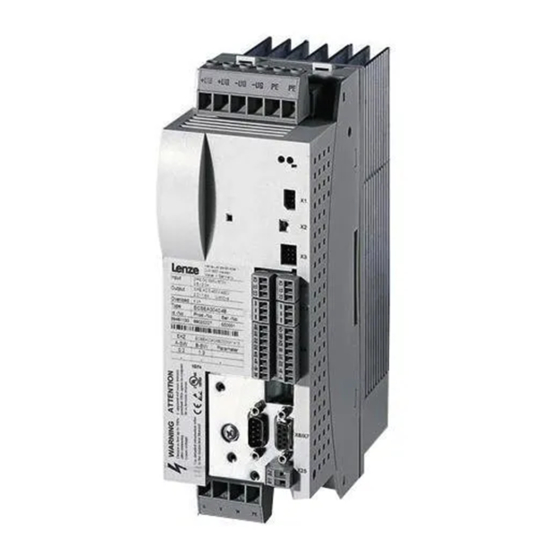
- Page 1 EDBCSXP064 .LKr Operating Instructions ECSEPxxx / ECSDPxxx / ECSCPxxx Axis module ˘ "Posi & Shaft"...
- Page 2 0Fig. 0Tab. 0 © 2013 Lenze Drive Systems GmbH, Hans−Lenze−Straße 1, 31855 Aerzen No part of this documentation may be reproduced or made accessible to third parties without written consent by Lenze Drive Sy- stems GmbH. All information given in this documentation has been selected carefully and complies with the hardware and software described.
- Page 3 ECSEA_003A EDBCSXP064 EN 8.0...
- Page 4 Scope of supply Position Description Quantity ECSLP... axis module Accessory kit with fixing material corresponding to the design (L): "E" − standard panel−mounted unit "D" − push−through technique "C" − cold−plate technique Mounting Instructions Drilling jig Functional earth conductor (only ECSDP...) Note! The ECSZA000X0B connector set must be ordered separately.
-
Page 5: Table Of Contents
............General safety and application notes for Lenze controllers . - Page 6 Contents Electrical installation ............Installation according to EMC (installation of a CE−typical drive system) .
- Page 7 ....... . . Entry of motor data for Lenze motors .
- Page 8 Contents 6.16 Setting of homing parameters ......... . 6.16.1 Setting homing modes .
- Page 9 Contents 6.26 Evaluation of hardware limit switches ........6.27 Controller enable (CINH = 0) .
- Page 10 Contents Monitoring functions ............Fault responses .
- Page 11 Contents Troubleshooting and fault elimination ........11.1 Fault analysis .
-
Page 12: Preface And General Information
Preface and general information About these Operating Instructions Preface and general information About these Operating Instructions These Operating Instructions will assist you in connecting and commissioning the ECSxP... axis modules. They contain safety instructions which must be observed! All persons working on and with the ECSxP... axis modules must have the Operating Instructions available and must observe the information and notes relevant for their work. -
Page 13: Terminology Used
(PLC) or further controllers exclusively via the X4 interface. Interface X14 (CAN−AUX) is exclusively used for parameter setting and diagnostics. Drive PLC Developer Studio (Lenze software for PLC programming acc. to IEC 61131) Global Drive Control (Lenze software for parameter setting and diagnostics) -
Page 14: Code Descriptions
Preface and general information About these Operating Instructions Code descriptions 1.1.2 Code descriptions Lenze codes are described in the form of tables with the following structure: Column Abbreviation Meaning Cxxxx Code no. Cxxxx Subcode 1 of Cxxxx Subcode 2 of Cxxxx... -
Page 15: Features Of The Ecsxp Axis Module
Supported feedback systems: ƒ – Resolver with and without position storage – Encoder (incremental encoder (TTL encoder), sin/cos encoder) Commissioning, parameter setting and diagnostics with the Lenze parameter ƒ setting and operating program "Global Drive Control" (GDC) or the XT EMZ9371BC keypad... -
Page 16: Scope Of Supply
Components for operation and communication ƒ Brake resistors ƒ Mains fuses ƒ Mains chokes ƒ RFI filters ƒ Tip! Information and auxiliary devices related to the Lenze products can be found in the download area at http://www.Lenze.com EDBCSXP064 EN 8.0... -
Page 17: Legal Regulations
Instructions. The specifications, processes, and circuitry described in these Instructions are for guidance only and must be adapted to your own specific application. Lenze does not take responsibility for the suitability of the process and circuit proposals. -
Page 18: Safety Instructions
Lenze Automation GmbH does not accept any liability for the suitability of the procedures and circuit proposals described. Depending on their degree of protection, some parts of the Lenze controllers ƒ (frequency inverters, servo inverters, DC speed controllers) and their accessory components can be live, moving and rotating during operation. - Page 19 Safety instructions General safety and application notes for Lenze controllers Application as directed Controllers are components which are designed for installation in electrical systems or machines. They are not to be used as domestic appliances, but only for industrial purposes according to EN 61000−3−2.
- Page 20 Reduce housing openings and cutouts to a minimum. Lenze controllers may cause a DC current in the PE conductor. If a residual current device (RCD) is used for protection against direct or indirect contact for a controller with three−phase supply, only a residual current device (RCD) of type B is permissible on the...
- Page 21 Safety instructions General safety and application notes for Lenze controllers Safety functions Certain controller versions support safety functions (e.g. "Safe torque off", formerly "Safe standstill") according to the requirements of the EC Directive 2006/42/EC (Machinery Directive). The notes on the integrated safety system provided in this documentation must be observed.
-
Page 22: Thermal Motor Monitoring
179 s in the event of a motor with a thermal motor time constant of 5 minutes (Lenze setting C0128), a motor current of 1.5 x I and a trigger threshold of 100 %. -
Page 23: Forced Ventilated Or Naturally Ventilated Motors
C0120 (OC6) or C0127 (OC8). Read release time in the diagram Diagram for detecting the release times for a motor with a thermal motor time constant of 5 minutes (Lenze setting C0128): = 1 × I L [%] = 3 ×... -
Page 24: Self−Ventilated Motors
C0129/x. Parameter setting The following codes can be set for I x t monitoring: Code Meaning Value range Lenze setting C0066 Display of the I x t load of the motor 0 ... 250 % − C0120 Threshold: Triggering of error "OC6"... - Page 25 Safety instructions Thermal motor monitoring Self−ventilated motors Calculate release time and I x t load Calculate the release time and the I x t load of the motor considering the values in C0129/1 and C0129/2(evaluation coefficient "y"). Formulae for release time Information Release time of the I x t monitoring...
-
Page 26: Residual Hazards
ECSxE supply module and the input current ƒ limitation is activated depending on the DC−bus voltage (C0175 = 1 or 2). the axis module is not supplied via a supply module delivered by Lenze. ƒ the low−voltage supply (24 V) is switched off. - Page 27 Motor protection Only use motors with a minimum insulation resistance of û = 1.5 kV, ƒ min. du/dt = 5 kV/ms. – Lenze motors meet these requirements. When using motors with an unknown insulation resistance, please contact your ƒ motor supplier.
-
Page 28: Safety Instructions For The Installation According To Ul
Safety instructions Safety instructions for the installation according to UL Safety instructions for the installation according to UL Warnings! General markings: Use 60/75 °C or 75 °C copper wire only. ƒ Maximum ambient temperature 55 °C, with reduced output current. ƒ... -
Page 29: Notes Used
Safety instructions Notes used Notes used The following pictographs and signal words are used in this documentation to indicate dangers and important information: Safety instructions Structure of safety instructions: Danger! (characterises the type and severity of danger) Note (describes the danger and gives information about how to prevent dangerous situations) Pictograph and signal word Meaning... -
Page 30: Technical Data
Technical data General data and operating conditions Technical data General data and operating conditions Standards and operating conditions Conformity Low−Voltage Directive (2006/95/EG) Approvals UL 508C Power Conversion Equipment Underwriter Laboratories (File No. E132659) CSA 22.2 No. 14 for USA and Canada Max. - Page 31 Technical data General data and operating conditions General electrical data Compliance with the requirements acc. to EN 61800−3 Noise emission Compliance with the limit class C2 acc. to EN 61800−3 (achieved by using collective filters typical for the application) Noise immunity Requirements acc.
-
Page 32: Rated Data
Technical data Rated data Rated data Axis module Rated data Type ECSxL004 ECSxL008 ECSxL016 Output power 400 V mains [kVA] rated Data for operation with upstream power supply module mains on mains voltage DC−bus voltage 15 ... 770 DC−bus DC−bus current DC−bus Rated output current at 4 kHz (causes a heatsink temperature of 70°C at an ambient... - Page 33 Technical data Rated data Rated data Type Axis module ECSxL032 ECSxL048 ECSxL064 Output power 400 V mains [kVA] 11.2 13.2 rated Data for operation with upstream power supply module mains on mains voltage DC−bus voltage 15 ... 770 DC−bus DC−bus current 15.6 12.5 20.9...
-
Page 34: Current Characteristics
Technical data Current characteristics Increased continuous current depending on the control factor Current characteristics 3.3.1 Increased continuous current depending on the control factor In the lower speed range ˘ the motor does not need the full motor voltage ˘ particularly the more powerful ECS axis modules can be permanently operated with increased output ^ 32). - Page 35 Technical data Current characteristics Increased continuous current depending on the control factor The following table shows the connections between mains voltage, DC−bus voltage and motor voltage: Mains voltage DC−bus voltage Output voltage (motor voltage) nominally achievable for 100 % x 1.35] mains mains modulation...
- Page 36 Technical data Current characteristics Increased continuous current depending on the control factor Example: The ECS axis module suitable for operation in conjunction with a Lenze motor of type MCS 14L32 is to be determined. Rated motor data ƒ – Rated motor torque (M ) = 17.2 Nm...
-
Page 37: Device Protection By Current Derating
Technical data Current characteristics Device protection by current derating 3.3.2 Device protection by current derating The maximum output current is limited. With output frequencies < 5 Hz the limitation depends on the heatsink temperature. ‚ 1.00 1.00 Iout ≤ 70 °C Imax ... -
Page 38: Mechanical Installation
Mechanical installation Important notes Mechanical installation Important notes Axis modules of the ECS series provide IP20 enclosure and can therefore only be ƒ used for installation in control cabinets. If the cooling air contains air pollutants (dust, fluff, grease, aggressive gases): ƒ... -
Page 39: Mounting With Fixing Rails (Standard Installation)
Mechanical installation Mounting with fixing rails (standard installation) Dimensions Mounting with fixing rails (standard installation) 4.2.1 Dimensions Note! Mounting with ECSZS000X0B shield mounting kit: Mounting clearance below the module > 195 mm ƒ ECSxA005 Fig. 4−1 Dimensions for "panel−mounted" design Axis module Dimensions [mm] Type... -
Page 40: Mounting Steps
Mechanical installation Mounting with fixing rails (standard installation) Mounting steps 4.2.2 Mounting steps How to install the axis module: 1. Prepare the fixing holes on the mounting surface. – Use the drilling jig for this purpose. 2. Take the fixing rails from the accessory kit in the cardboard box. 3. -
Page 41: Mounting With Thermal Separation (Push−Through Technique)
Mechanical installation Mounting with thermal separation (push−through technique) Mounting with thermal separation (push−through technique) For the push−through technique the rear panel of the control cabinet must be a steel plate with a thickness of at least 2 mm. The edges of the mounting cutout and the fixing holes for the clamps must be slightly curved inwards (towards the axis module). -
Page 42: Dimensions
Mechanical installation Mounting with thermal separation (push−through technique) Dimensions 4.3.1 Dimensions Note! Mounting with ECSZS000X0B shield mounting kit: Mounting clearance below the module > 195 mm ƒ ECSXA007 Fig. 4−2 Dimensions for "push−through design" Mounting cutout (a1 x b1), ^ 43 Axis module Dimensions [mm] Type... - Page 43 Mechanical installation Mounting with thermal separation (push−through technique) Dimensions Dimensions of mounting cutout Note! Installation with shield mounting ECSZS000X0B: Clearance below the mounting cutout > 220 mm ƒ ECSXA063 Fig. 4−3 Dimensions of mounting cutout Mounting surface Mounting cutout for size 0 Mounting cutout for size 1 Axis module Dimensions [mm]...
-
Page 44: Mounting Steps
Mechanical installation Mounting with thermal separation (push−through technique) Mounting steps 4.3.2 Mounting steps How to mount the axis module: 1. Prepare the fixing holes for the wire clamps on the mounting area. For this purpose, apply a drilling jig. 2. Prepare the mounting cutout. The edges of the mounting cutout and the fixing holes for the wire clamps have to be slightly arched inwardly (to the axis module). -
Page 45: Mounting In Cold−Plate Design
Mechanical installation Mounting in cold−plate design Mounting in cold−plate design The axis modules ECSC... are intended for mounting in cold−plate design (e.g. on collective coolers). Requirements for collective coolers The following requirements must be met to ensure a safe operation of the axis modules: Good thermal contact with the cooler ƒ... -
Page 46: Dimensions
Mechanical installation Mounting in cold−plate design Dimensions 4.4.1 Dimensions Note! Mounting with ECSZS000X0B shield mounting kit: Mounting clearance below the module > 195 mm ƒ ECSXA009 Fig. 4−5 Dimensions for "cold−plate design" Axis module Dimensions [mm] Type Size ECSC ECSC 88,5 ECSC ECSC... -
Page 47: Mounting Steps
Mechanical installation Mounting in cold−plate design Mounting steps 4.4.2 Mounting steps À Á Â ECSXA030 Fig. 4−6 Mounting for "cold−plate design" Proceed as follows to mount the axis module: 1. Prepare the fixing holes on the mounting plate. – Use a drilling jig for this purpose. 2. -
Page 48: Electrical Installation
Electrical installation Installation according to EMC (installation of a CE−typical drive system) Electrical installation Installation according to EMC (installation of a CE−typical drive system) General information The electromagnetic compatibility of a machine depends on the type of installation ƒ and care taken.Especially consider the following: –... - Page 49 Electrical installation Installation according to EMC (installation of a CE−typical drive system) Assembly Connect the ECS modules, RFI filters, and mains choke to the earthed mounting ƒ plate with a surface as large as possible: – Mounting plates with conductive surfaces (zinc−coated or stainless steel) allow for permanent contact.
- Page 50 Electrical installation Installation according to EMC (installation of a CE−typical drive system) Shielding Connect the motor cable shield to the axis module ƒ – with the ECSZS000X0B shield mounting kit. – extensively to the mounting plate below the axis module. –...
-
Page 51: Power Terminals
Electrical installation Power terminals Power terminals ECSXA080 Fig. 5−1 Plug connectors for power terminals Danger! Dangerous voltage The leakage current to earth (PE) is > 3.5 mA AC or > 10 mA DC. Possible consequences: Death or severe injuries when the device is touched in the event of a fault. ƒ... - Page 52 Electrical installation Power terminals All power connections are plug connections and coded. The ECSZA000X0B plug ƒ connector set must be ordered separately. Installation of the cables to EN 60204−1. ƒ The cables used must comply with the approvals required at the site of use (e.g. VDE, ƒ...
- Page 53 Electrical installation Power terminals Shielded cables The following factors decisively determine the effect of the shielded cables: Good shield connection ƒ – Ensure a contact surface as large as possible Low shield resistance ƒ – Only use shields with tin−plated or nickel−plated copper braids (shields with steel braids cannot be used).
-
Page 54: Connection To The Dc Bus (+Ug, −Ug)
Electrical installation Power terminals Connection to the DC bus (+U , −U 5.2.1 Connection to the DC bus (+U , −U Stop! No device protection for DC bus voltage surges In passive axis modules (without 24 V−supply), the charging circuit can be overloaded through DC bus voltage surges. - Page 55 Power terminals Connection to the DC bus (+U , −U Fuses Mains fuses are not included in the Lenze delivery program. Use standard fuses. ƒ When using ECSxE power supply modules which are fused on the supply side the ƒ...
-
Page 56: Connection Plan For Mimimum Wiring With Internal Brake Resistor
Electrical installation Power terminals Connection plan for mimimum wiring with internal brake resistor 5.2.2 Connection plan for mimimum wiring with internal brake resistor Documentation of the ECSxE power supply module Observe the enclosed notes. Stop! Always operate the ECS power supply modules with a brake resistor (internal/external). - Page 57 Electrical installation Power terminals Connection plan for mimimum wiring with internal brake resistor F1...F3 " " L3 PE +UG +UG +UG +UG ECSEE... ECSxS/P/M/A... ECSxS/P/M/A... ECSDE... BD1 BD2 U V W PE BD1 BD2 U V W PE " " "...
-
Page 58: Connection Plan For Mimimum Wiring With External Brake Resistor
Electrical installation Power terminals Connection plan for mimimum wiring with external brake resistor 5.2.3 Connection plan for mimimum wiring with external brake resistor Documentation of the ECSxE power supply module Observe the enclosed notes. Stop! Always operate the ECS power supply modules with a brake resistor. ƒ... - Page 59 Electrical installation Power terminals Connection plan for mimimum wiring with external brake resistor F1...F3 " " L3 PE +UG +UG +UG +UG ECSxE... ECSxS/P/M/A... ECSxS/P/M/A... BD1 BD2 U V W PE BD1 BD2 U V W PE " " " "...
-
Page 60: Motor Connection
) when using synchronous motors or according to the rated motor current ) for asynchronous motors. Length of the unshielded ends: 40 ... 100 mm (depending on the cable cross−section) ƒ Lenze system cables meet these requirements. ƒ Use the ECSZS000X0B shield mounting kit for EMC−compliant wiring. ƒ... -
Page 61: Motor Holding Brake Connection
Electrical installation Power terminals Motor holding brake connection 5.2.5 Motor holding brake connection The motor holding brake is connected to X25/BD1 and X25/BD2. ƒ is supplied with low voltage via the terminals X6/B+ and X6/B−: ƒ +23 ... +30 V DC, max.1.5 A Stop! Protect X6/B+ with an F 1.6 A fuse. - Page 62 1.5 V is produced. The voltage drop can be compensated by a higher voltage at the cable entry. The voltage required at X6/B+ and X6/B− for the Lenze system cables is calculated as follows: [V] + U [V] ) 0.08...
-
Page 63: Connection Of An Ecsxk
Electrical installation Power terminals Connection of an ECSxK... capacitor module (optional) 5.2.6 Connection of an ECSxK... capacitor module (optional) The ECS capacitor modules support the DC−bus voltage for the drive system. These capacitor module types are available: ECSxK001 (705 mF, ±20 %) ƒ... -
Page 64: Control Terminals
Electrical installation Control terminals Control terminals ECSXA070 Fig. 5−7 Plug connectors for control terminals (X6) For the supply of the control electronics an external 24 V DC voltage at terminals X6/+24 and X6/GND is required. Stop! The control cables must always be shielded to prevent interference ƒ... - Page 65 Electrical installation Control terminals Shield connection of control cables and signal cables The plate on the front of the device serves as the mounting place (two threaded holes M4) for the shield connection of the signal cables. The screws used may extend into the inside of the device by up to 10 mm.
- Page 66 (central controller enable) of the power supply module via the relay 0. – In the default Lenze setting of the ECS axis modules, DO1 is set to "ready". "Ready" is only present if a specified DC−bus voltage has been reached.
- Page 67 Electrical installation Control terminals Assignment of the plug connectors Plug connector X6 Terminal Function Electrical data X6/+24 Low−voltage supply of the control electronics 20 ... 30 V DC, 0. A (max. 1 A) for starting current of 24 V: X6/GND Reference potential of low−voltage supply max.
-
Page 68: Digital Inputs And Outputs
Electrical installation Control terminals Digital inputs and outputs 5.3.1 Digital inputs and outputs Stop! If an inductive load is connected to X6/DO1, a spark suppressor with a limiting function to max. 50 V ± 0 % must be provided. GNDext DI1 DI2 DI3 DI4 "... -
Page 69: Analog Input
Electrical installation Control terminals Analog input 5.3.2 Analog input " " ECSXA015 Fig. 5−10 Analog input at X6 " HF−shield termination by large−surface connection to functional earth (see Mounting Instructions for ECSZS000X0B shield mounting kit) Analog input configuration Use C0034 to set whether the input is to be used for a master voltage (±10 V) or a ƒ... -
Page 70: Safe Torque Off
Electrical installation Control terminals Safe torque off 5.3.3 Safe torque off The axis modules support the "safe torque off" safety function (formerly "safe standstill"), "protection against unexpected start−up", in accordance with the requirements of EN ISO 13849−1, Performance Level Pld. For this purpose, the axis modules are equipped with two independent safety paths. - Page 71 Electrical installation Control terminals Safe torque off 5.3.3.2 Functional description The "safe torque off" state can be initiated any time via the input terminals X6/SI1 (controller enable/inhibit) and X6/SI2 (pulse enable/inhibit). For this purpose a LOW level has to be applied at both terminals: X6/SI1 = LOW (controller inhibited): ƒ...
- Page 72 Electrical installation Control terminals Safe torque off 5.3.3.3 Important notes Danger! When using the "safe torque off" function, additional measures are required for "emergency stops"! There is neither an electrical isolation between motor and axis module nor a "service" or "repair switch". Possible consequences: Death or severe injuries ƒ...
- Page 73 Electrical installation Control terminals Safe torque off 5.3.3.4 Technical data Terminal assignment Plug connector X6 Terminal Function Level Electrical data X6/S24 Low−voltage supply 18 ... 30 V DC 0.7 A X6/SO "Safe torque off" feedback During operation 24 V DC output 0.7 A (max.
- Page 74 Electrical installation Control terminals Safe torque off 5.3.3.5 Function check After installation the operator must check the "safe torque off" function. ƒ The function check must be repeated at regular intervals, after one year at the ƒ latest. Stop! If the function check leads to impermissible states at the terminals, commissioning cannot take place! Test specifications Check the circuitry with regard to correct function.
- Page 75 Electrical installation Control terminals Safe torque off 5.3.3.6 Example: Wiring with electronic safety switching device "Pilz PNOZ e1vp" for Performance Level Pl 24V DC Start ECSxS/P/M/A Not-Halt/ Emergency stop Pilz PNOZ e1vp 10s 24V DC Pilz 774195 Pilz 774195 ECSXA034 Fig.
- Page 76 PL in accordance with EN ISO 13849−1 or SIL 2 in accordance with EN 62061 are to be used in all upstream applications! Interconnection examples can be found in the download area (Application Knowledge Base) at: www.Lenze.com EDBCSXP064 EN 8.0...
- Page 77 Electrical installation Control terminals Safe torque off 5.3.3.7 Example: Wiring with electromechanical safety switching device "Siemens 3TK2827" for Performance Level Pl Not-Halt/ Emergency stop 24V DC Siemens 3TK2827 ECSxS/P/M/A Start ECSXA035 Fig. 5−13 Example: Wiring with "Siemens 3TK2827" safety switching device T1 Test key 1 T2 Test key 2 The motor is shut down in accordance with stop category 1 of EN 60204 when the...
- Page 78 PL in accordance with EN ISO 13849−1 or SIL 2 in accordance with EN 62061 are to be used in all upstream applications! Interconnection examples can be found in the download area (Application Knowledge Base) at: www.Lenze.com EDBCSXP064 EN 8.0...
-
Page 79: Automation Interface (Aif)
Electrical installation Automation interface (AIF) Automation interface (AIF) The keypad XT or a communication module can be attached to or removed from the automation interface (X1). This is also possible during operation. The keypad XT serves to enter and visualise parameters and codes. ƒ... -
Page 80: Wiring Of System Bus (Can)
MotionBus (CAN) with master control ECS_COB007 Fig. 5−15 MotionBus (CAN) with controller as master MotionBus (CAN), interface X4 System bus (CAN), interface X14 Master Slave PC with the Lenze parameter setting and operating software (GDC, GDL, GDO) HMI / operating unit EDBCSXP064 EN 8.0... - Page 81 Electrical installation Wiring of system bus (CAN) ECS_COB003 Fig. 5−16 Bus connections on the controller Assignment of the plug connectors X4 (CAN) X14 (CAN−AUX) Description CAN−HIGH CAN−LOW Reference potential Specification of the transmission cable We recommend the use of CAN cables in accordance with ISO 11898−2: CAN cable in accordance with ISO 11898−2 Cable type Paired with shielding...
- Page 82 Electrical installation Wiring of system bus (CAN) System bus (CAN) wiring ECS_COB004 Fig. 5−17 Example: System bus (CAN) wiring via interface X4 ECS axis module Master control, e.g. ETC Note! Connect one bus terminating resistor (120 W) each to the first and last node of the system bus (CAN).
- Page 83 Electrical installation Wiring of system bus (CAN) Bus cable length Note! The permissible cable lengths must be observed. 1. Check the compliance with the total cable length in Tab. 5−1. The baud rate determines the total cable length. CAN baud rate [kbit/s] Max.
- Page 84 It is not possible to use a cable length of 450 m without using a repeater. After 360 m (point 2) a repeater must be installed. Result The Lenze repeater type 2176 is used (cable reduction: 30 m) Calculation of the maximum cable length: First segment: 360 m Second segment: 360 m (according to Tab.
-
Page 85: Wiring Of The Feedback System
(e.g. by using separating webs or separated trailing cables) is not ensured on the entire cable length cable due to an installation on the system side, the encoder cable must be provided with an insulation resistance of 300 V. Lenze encoder cables meet this requirement. -
Page 86: Resolver Connection
Wiring of the feedback system Resolver connection 5.6.1 Resolver connection Note! Use the prefabricated Lenze system cables for the connection of a resolver. ƒ Cable length: max. 50 m ƒ Depending on the cable length and resolver used parameterise the code ƒ... -
Page 87: Encoder Connection
Electrical installation Wiring of the feedback system Encoder connection 5.6.2 Encoder connection Danger! Valid when using an operating software up to and including V7.0: When absolute value encoders are used, uncontrolled movements of the drive are possible! If an absolute value encoder is disconnected from the axis module during operation, the fault OH3−TRIP occurs. - Page 88 Electrical installation Wiring of the feedback system Encoder connection Incremental encoder (TTL encoder) Features Input/output frequency: 0 ... 200 kHz Current consumption: 6 mA per channel Current on output V (X8/pin 4): Max. 200 mA < 50 m R1 (+KTY) R2 (-KTY) ECSXA026 Fig.
- Page 89 Electrical installation Wiring of the feedback system Encoder connection SinCos encoders and SinCos absolute value encoders with Hiperface Features Input/output frequency: 0 ... 200 kHz 221 W Internal resistance (R Offset voltage for signals SIN, COS, Z: 2.5 V The differential voltage between signal track and reference track must not exceed ƒ...
-
Page 90: Digital Frequency Input/Output (Encoder Simulation)
Electrical installation Wiring of the feedback system Digital frequency input/output (encoder simulation) 5.6.3 Digital frequency input/output (encoder simulation) The digital frequency coupling of ECSxS/P/A axis modules basically is effected as a master−slave connection via the interface X8. This interface can either be used as a digital frequency input or as a digital frequency output (e. - Page 91 Electrical installation Wiring of the feedback system Digital frequency input/output (encoder simulation) 2 to 3 slaves connected to the master: ƒ Use the EMF2132IB digital frequency distributor to wire the ECS axis modules with master digital frequency cable EYD0017AxxxxW01W01 and slave digital frequency cable EYD0017AxxxxW01S01.
-
Page 92: Commissioning
Commissioning Basic terms of positioning Positioning Commissioning Basic terms of positioning 6.1.1 Positioning Positioning means to move one or several machine parts from a starting position to a defined target position. ‚ ECSXA405 Fig. 6−1 Example: Positioning of a linear positioning axis with spindle ... -
Page 93: Touch Probe Positioning
Commissioning Basic terms of positioning Touch probe positioning 6.1.2 Touch probe positioning During the touch probe positioning process the drive at first travels towards the selected target position until a mark sensor (touch probe signal) at the digital input X6/DI3 of the axis module responds. -
Page 94: Positioning Profile
Commissioning Basic terms of positioning Positioning profile 6.1.3 Positioning profile A positioning process is described by a "positioning profile ". It includes the following parameters: Positioning profile mode ƒ – "Absolute positioning", "continuous positioning", etc. Additional positioning profile function ƒ –... -
Page 95: Positioning Profile Mode
Commissioning Basic terms of positioning Positioning profile mode 6.1.4 Positioning profile mode You can select the following positioning profile modes via C3095/x: Positioning profile mode Setting Detailed description C3095/x ^ 193 Absolute positioning ^ 193 Relative positioning in continuous measuring system ^ 195 Continuous constant travel ^ 194... -
Page 96: Additional Functions Of The Positioning Profile (C3096/X)
Commissioning Basic terms of positioning Additional functions of the positioning profile (C3096/x) 6.1.5 Additional functions of the positioning profile (C3096/x) Speed override ƒ – The term "Override" refers to the variation of the speed set in the positioning profile via the analog input (10 V º 100 %) and/or by means of the process data object (PDO) via CAN, AIF, C4040. -
Page 97: Positioning Profile Parameters
Commissioning Basic terms of positioning Positioning profile parameters 6.1.6 Positioning profile parameters 6.1.6.1 Target position (C3100/x) The effect of this parameter depends on the type of the positioning carried out. Three basic types of positioning are differentiated: Absolute positioning ƒ –... - Page 98 Commissioning Basic terms of positioning Positioning profile parameters 6.1.6.2 Traversing speed (C3200/x) This parameter defines, with which max. speed the position is to be approached. Depending on the three positioning profile parameters "position", "acceleration" and "deceleration" it may occur that the drive does not reach the max. speed at all: v [m/s] ‚...
- Page 99 The setting of the jerk time under C3600/x serves to change over between L profile and S profile for generating the travel profile. Jerk time = 0, L profile is active (Lenze setting): ƒ The positioning profile is generated with linear ramps. All positioning profile modes (C3095/x) can be used.
- Page 100 Commissioning Basic terms of positioning Positioning profile parameters jerk jerk jerk jerk Jerk ECSXA429 Fig. 6−8 Jerk time C3600/x Process without jerk limitation Process with jerk limitation Standstill Accelerating with increasing acceleration (limited jerk) Accelerating with constant acceleration acc. to positioning profile (Acc, C3300/x) Accelerating with decreasing acceleration (limited jerk) Travelling with traversing speed acc.
-
Page 101: Setting Of Manual Jog (Inching Mode)
Commissioning Basic terms of positioning Setting of manual jog (inching mode) 6.1.7 Setting of manual jog (inching mode) "Manual jog" means running the drive by manual operation. ç è ECSXA419 Fig. 6−9 Manual jog (inching mode) The parameters "traversing speed", "acceleration" and "deceleration" can also be set ƒ... -
Page 102: Measuring System For Positioning
Commissioning Basic terms of positioning Measuring system for positioning 6.1.9 Measuring system for positioning Neg. limit switch Pos. limit switch Target position SW-LimNeg SW-LimPos C3041 C3040 C3011, C3012 Zero position Home position ECSXA404 Fig. 6−11 Measuring system for the positioning The measuring system for positioning has the following features: The zero position of the measuring system has a firm reference to the machine due ƒ... -
Page 103: Machine Parameters
Commissioning Basic terms of positioning Machine parameters 6.1.10 Machine parameters A positioning process requires the machine parameters to convert the entries in the application units into a device−internal incremental representation (inc). The GDC contains the codes for setting the machine parameters in the parameter menu under Positioning W Machine parameters. - Page 104 Commissioning Basic terms of positioning Machine parameters Gearbox ratio (C1202/C1203) The gearbox ratio specifies the number of revolutions of the motor axis at which the spindle revolves exactly once. It is entered into the codes C1202 (gearbox factor numerator) and C1203 (gearbox factor denominator).
- Page 105 Commissioning Basic terms of positioning Machine parameters Feed constant (C1204) The feed constant specifies the path (in units) the load (slide) covers in one revolution of the spindle. It is entered into code C1204: [mm, cm, AAA] C1204 units rev. + Feed [1 rev.] The physical size of a unit is defined in this way via C1204.
- Page 106 Commissioning Basic terms of positioning Machine parameters Maximum target position selection (C4265) The maximum target position selection results from the possible traversing range of 16384 position encoder revolutions converted into real units. C4265 + 16384 [rev.] @ 65536 [incr. rev.] @ 10000 @ C1204 @ C1203 @ C1200 65536 @ C1202 @ C1201 C4265 is limited to ±214000.0000 units.
-
Page 107: Electrical Shaft ("Eshaft")
Commissioning Basic terms of positioning Electrical shaft ("EShaft") Software limit positions (C3040/C3041) As well as defining the zero position it is important to define the limits of travel range to avoid damages of the system, e. g. at manual control. These limits (limit switches/limit positions) can be defined by hardware and software: Hardware limit switches are linked with the digital inputs of the controller;... -
Page 108: Device Structure And Interfaces To The Higher−Level Control
Device structure and interfaces to the higher−level control The ECSxP axis module with the "Posi and Shaft" application program requires a higher−level control (e. g. Lenze Drive PLC) for the coordination of the positioning process. The "Posi and Shaft" application program enables input and storage of individual positioning profiles and the accompanying profile parameters (target position, traversing speed, acceleration, etc.). - Page 109 Commissioning Basic terms of positioning Device structure and interfaces to the higher−level control The following control interfaces are available for the controller under code C4010: Automation interface (AIF) X1 ƒ – 4 process data words (in conjunction with the EMF2192IB EtherCAT communication module, sync−controlled via the terminal X6/DI1) MotionBus (CAN) connection X4 ƒ...
-
Page 110: State Control Of The Positioning Drive
Commissioning State control of the positioning drive State control of the positioning drive Device enable Init Trouble Positioning Init Ok Stat1.PStateTrouble = 1 (TRUE) Stat1.PStatePos = 1 (TRUE) Stand-By ManualJog Homing Stat1.PStateManJog = 1 (TRUE) Stat1.PStateHome = 1 (TRUE) PosFunctions ECSXA403 Fig. -
Page 111: Operating States
Commissioning State control of the positioning drive Operating states 6.2.1 Operating states "PosFunctions" state These functions are permanently active, irrespective of the transitions of the state control. In the states the following "PosFunctions" are carried out: General control functions ƒ Calculation of the monitoring functions (software limit positions, hardware limit ƒ... - Page 112 Commissioning State control of the positioning drive Operating states "ManualJog" state This state enables manual traversing of the drive system (manual jog/inching mode) The following actions are executed in "ManualJog": Creation of motion profiles for the function "ManualJog" (manual control). ƒ...
-
Page 113: Conditions For State Change (Transitions)
Commissioning State control of the positioning drive Conditions for state change (transitions) 6.2.2 Conditions for state change (transitions) The figure below shows the conditions to be fulfilled for the individual state changes in the form of logic operations: Ctrl1.TripSet = 0 (set fault message) ³1 EnterTrouble Fault active... - Page 114 Commissioning State control of the positioning drive Conditions for state change (transitions) Ctrl1.JogCCW = 0 ³1 & ExitManual Ctrl1.JogCW = 0 Ctrl1.RelLimSwitch = 0 (no retracting) HW limit switch_positive= 1 HW limit switch_negative= 1 Speed setpoint = 0 Stat1.GlobalErr = 1 (fault occurred) Ctrl1.Qsp = 1 (user QSP) Ctrl1.Imp = 1 (pulse inhibit) Stat1.GlobalErr = 0 (no fault)
-
Page 115: Before You Start
Commissioning Before you start Before you start Note! The use of a Lenze motor is assumed in this description of the ƒ commissioning steps. For details on the operation with other motors see ^ 244. The operation with the Lenze parameter setting and operating program ƒ... -
Page 116: Commissioning Steps (Overview)
Commissioning Commissioning steps (overview) Commissioning steps (overview) Start Carry out basic settings (^ 117) Operation with continuous positioning Operation with linear positioning axis axis ECSXA452 ECSXA451 Set manual jog Set manual jog (inching mode) (inching mode) (^ 121) (^ 121) Set homing (^ 122) Set positioning... -
Page 117: Basic Settings With Gdc
ð The drive is identified and the parameter menu is opened. ^ 125 Load Lenze setting. Not required for initial commissioning of the axis module. Only recommended if the Lenze setting is unclear. Set communication Comm. parameters − CAN interface: ^ 266... - Page 118 Detailed information ^ 132 Set feedback system. Set Lenze motors with resolvers (standard) in the GDC parameter menu under Short setup W Feedback system. Set other resolvers and encoders in the GDC parameter menu under Motor/feedback systems W Feedback system.
-
Page 119: Set Reference
Commissioning Commissioning steps (overview) Set reference 6.4.2 Set reference Note! Setting the reference (homing) is required ... in the case of initial commissioning of an absolute value encoder ƒ (multi−turn/single−turn); after the replacement of an encoder, controller, or motor; ƒ if modifications regarding the mechanics are carried out. - Page 120 Commissioning Commissioning steps (overview) Set reference Setting sequence Setting Brief description Detailed information Preconditions The axis module is ready for operation (RDY). – Check with C0183, C0168/1 – Green LED is blinking, red LED is off Controller inhibit is active. –...
-
Page 121: Setting Of Manual Jog (Inching Mode)
Commissioning Commissioning steps (overview) Setting of manual jog (inching mode) 6.4.3 Setting of manual jog (inching mode) Stop! Machine parts can be damaged or destroyed! The drive can travel into a mechanical limit during manual jog if no reference is known (status bit Stat1.HomePosAvailable = 0, ^ 161). ƒ... -
Page 122: Setting Of Homing
Commissioning Commissioning steps (overview) Setting of homing 6.4.4 Setting of homing Note! Homing only is necessary when operating with a linear positioning axis. ƒ Comply with the commissioning steps in the given order! ƒ Setting Brief description Detailed information ^ 177 Set homing parameters. -
Page 123: Setting Absolute Positioning/Relative Continuous Positioning
Commissioning Commissioning steps (overview) Setting absolute positioning/relative continuous positioning 6.4.5 Setting absolute positioning/relative continuous positioning Note! Absolute positioning is required for operation with a linear positioning axis. ƒ Relative positioning in the continuous measuring system is required for ƒ operation with a continuous positioning axis. Comply with the commissioning steps in the given order! ƒ... - Page 124 Commissioning Commissioning steps (overview) Setting absolute positioning/relative continuous positioning Operation with a continuous positioning axis Operation with a linear positioning axis Inhibit controller. Press the <F9> key in GDC. X6/SI1 orX6/SI2 must be open (LOW). C4040/bit 9 = 1 (Ctrl1.Rsp) Set the operating mode required for the application via C4010 in the GDC parameter menu under Short setup W Operating mode.
-
Page 125: Loading The Lenze Setting
Loading the Lenze setting Loading the Lenze setting Note! When loading the Lenze setting, all parameters are reset to the basic setting defined by Lenze. Settings that have been adjusted before get lost during this process! In GDC, you can find the parameters and codes to be set in the parameter menu in Load / Save / PLC. -
Page 126: Setting Of Mains Data
Therefore, set C0175 = 3 for the axis modules (charging current limitation inactive, charging resistor short−circuited). If the Lenze setting has been loaded via C0002, C0175 = 3 must be reset. Cyclic switching of the mains voltage at the power supply module can ƒ... -
Page 127: Setting The Voltage Thresholds
[V AC] [V DC] [V DC] yes/no yes/no 400 ... 460 yes/no yes/no C0174 C0174 + 5 V 400 (Lenze setting) yes/no C0174 C0174 + 5 V 400 ... 460 yes/no C0174 C0174 + 5 V C0174 C0174 + 5 V... -
Page 128: Entry Of Motor Data For Lenze Motors
The following only describes the parameter setting for Lenze motors! (If you ƒ use a motor from another manufacturer, see ^ 244.) If the Lenze setting has been loaded via C0002, the motor data must be ƒ re−entered. The freely available "GDC−Easy" does not provide the "Input assistant for ƒ... - Page 129 Commissioning Entry of motor data for Lenze motors ECSXA302 Fig. 6−21 GDC view: Motor selection 3. Select the connected motor from the list (see motor nameplate). – The corresponding motor data is displayed in the "Motor data" fields on the right.
-
Page 130: Holding Brake Configuration
Commissioning Holding brake configuration Holding brake configuration Tip! If you use a motor without a holding brake, you can skip this chapter. v [m/s] C4023 t [s] Bits: Ctrl1.ProfEnable Ctrl1.JogCCW Ctrl1.JogCW Ctrl1.RelLimSwitch t [s] X25 (Relay) t [s] Bit: Stat1.Imp t [s] C4022 C4021... - Page 131 Commissioning Holding brake configuration Code Possible settings IMPORTANT Designation Lenze/ Selection {Appl.} ^ 136 [C0420] Encoder const. Number of increments of the ^ 145 encoder {1 inc/rev} 8192 Sets C0419 = 0 ("common") if the value is altered. ^ 130...
-
Page 132: Setting Of The Feedback System For Position And Speed Control
More parameters or codes for setting the feedback system can be found in the parameter menu under Motor/feedback system W Feedback system. Note! If the Lenze setting has been loaded via C0002, the feedback system must be reset. EDBCSXP064 EN 8.0... -
Page 133: Resolver As Position And Speed Encoder
Resolver as position and speed encoder If a resolver is connected to X7 and used as a position and speed encoder, no settings are necessary. Lenze setting: Resolver as position encoder: C0490 = 0 ƒ Resolver as speed encoder: C0495 = 0 ƒ... - Page 134 Selection {Appl.} ^ 249 C0058 Rotor diff −90.0 Rotor displacement angle (offset angle) Input in case of Lenze motor with resolver: −90° hiperface absolute value encoder: 0° Code value is adapted by the rotor position adjustment function (C0095). Only relevant for the operation of synchronous motors.
-
Page 135: Resolver As Absolute Value Encoder
(number of pole pairs > 1): 180° Max. rotation + " number_of_pole_pairs Code Possible settings IMPORTANT Designation Lenze/ Selection {Appl.} ^ 135 C3002 NoChangeOf Resolver as absolute value encoder ChangeOfPos After "mains off/on", homing has to be carried out. -
Page 136: Ttl/Sincos Encoder As Position And Speed Encoder
Commissioning Setting of the feedback system for position and speed control TTL/SinCos encoder as position and speed encoder 6.9.3 TTL/SinCos encoder as position and speed encoder If an incremental encoder or a SinCos encoder without serial communication is connected to X8 and used for position and speed control, comply with the following setting sequence: 1. - Page 137 Selection {Appl.} ^ 249 C0058 Rotor diff −90.0 Rotor displacement angle (offset angle) Input in case of Lenze motor with resolver: −90° hiperface absolute value encoder: 0° Code value is adapted by the rotor position adjustment function (C0095). Only relevant for the operation of synchronous motors.
- Page 138 Active ^ 136 [C0419] Enc. setup Encoder selection ^ 145 Selection of encoder type indicated on the nameplate of the Lenze motor. The encoder data (C0420, C0421, C0427) is set automatically in accordance with the selection. Common IT512−5V Incremental encoder with TTL level IT1024−5V...
- Page 139 Commissioning Setting of the feedback system for position and speed control TTL/SinCos encoder as position and speed encoder Code Possible settings IMPORTANT Designation Lenze/ Selection {Appl.} ^ 136 [C0427] Enc. signal Function of the master frequency ^ 145 input signals on X8 (DFIN) 2−phase...
-
Page 140: Ttl/Sincos Encoder As Position Encoder And Resolver As Speed Encoder
Commissioning Setting of the feedback system for position and speed control TTL/SinCos encoder as position encoder and resolver as speed encoder 6.9.4 TTL/SinCos encoder as position encoder and resolver as speed encoder A TTL incremental encoder connected to X8 or a SinCos encoder without serial communication can be configured as a position encoder with a resolver connected to X7 being used as a speed encoder. - Page 141 Selection {Appl.} ^ 249 C0058 Rotor diff −90.0 Rotor displacement angle (offset angle) Input in case of Lenze motor with resolver: −90° hiperface absolute value encoder: 0° Code value is adapted by the rotor position adjustment function (C0095). Only relevant for the operation of synchronous motors.
- Page 142 Setting of the feedback system for position and speed control TTL/SinCos encoder as position encoder and resolver as speed encoder Code Possible settings IMPORTANT Designation Lenze/ Selection {Appl.} ^ 249 [C0095] Rotor pos adj Activation of rotor position adjustment for automatic determination of the rotor displacement angle.
- Page 143 {Appl.} ^ 136 [C0419] Enc. setup Encoder selection ^ 145 Selection of encoder type indicated on the nameplate of the Lenze motor. The encoder data (C0420, C0421, C0427) is set automatically in accordance with the selection. Common IT512−5V Incremental encoder with TTL level IT1024−5V...
- Page 144 Commissioning Setting of the feedback system for position and speed control TTL/SinCos encoder as position encoder and resolver as speed encoder Code Possible settings IMPORTANT Designation Lenze/ Selection {Appl.} ^ 132 [C0491] X8 in/out Function of X8 X8 is input...
-
Page 145: Absolute Value Encoder As Position And Speed Encoder
Commissioning Setting of the feedback system for position and speed control Absolute value encoder as position and speed encoder 6.9.5 Absolute value encoder as position and speed encoder Danger! Valid when using an operating software up to and including V7.0: When absolute value encoders are used, uncontrolled movements of the drive are possible! If an absolute value encoder is disconnected from the axis module during... - Page 146 Commissioning Setting of the feedback system for position and speed control Absolute value encoder as position and speed encoder An absolute value encoder mounted on the motor shaft can be used without an additional resolver as position and speed encoder. 1.
- Page 147 Selection {Appl.} ^ 249 C0058 Rotor diff −90.0 Rotor displacement angle (offset angle) Input in case of Lenze motor with resolver: −90° hiperface absolute value encoder: 0° Code value is adapted by the rotor position adjustment function (C0095). Only relevant for the operation of synchronous motors.
- Page 148 Active ^ 136 [C0419] Enc. setup Encoder selection ^ 145 Selection of encoder type indicated on the nameplate of the Lenze motor. The encoder data (C0420, C0421, C0427) is set automatically in accordance with the selection. Common IT512−5V Incremental encoder with TTL level IT1024−5V...
- Page 149 Commissioning Setting of the feedback system for position and speed control Absolute value encoder as position and speed encoder Code Possible settings IMPORTANT Designation Lenze/ Selection {Appl.} ^ 136 [C0427] Enc. signal Function of the master frequency ^ 145 input signals on X8 (DFIN) 2−phase...
-
Page 150: Absolute Value Encoder As Position Encoder And Resolver As Speed Encoder
Commissioning Setting of the feedback system for position and speed control Absolute value encoder as position encoder and resolver as speed encoder 6.9.6 Absolute value encoder as position encoder and resolver as speed encoder Danger! Valid when using an operating software up to and including V7.0: When absolute value encoders are used, uncontrolled movements of the drive are possible! If an absolute value encoder is disconnected from the axis module during... - Page 151 Do not parameterise codes C0420, C0421 and C0427! ƒ 4. Save settings with C0003 = 1. Codes for feedback system selection Code Possible settings IMPORTANT Designation Lenze/ Selection {Appl.} ^ 132 [C0490] Feedback pos Selection of feedback system for positioning control Resolver at X7...
- Page 152 Selection {Appl.} ^ 249 C0058 Rotor diff −90.0 Rotor displacement angle (offset angle) Input in case of Lenze motor with resolver: −90° hiperface absolute value encoder: 0° Code value is adapted by the rotor position adjustment function (C0095). Only relevant for the operation of synchronous motors.
- Page 153 {Appl.} ^ 136 [C0419] Enc. setup Encoder selection ^ 145 Selection of encoder type indicated on the nameplate of the Lenze motor. The encoder data (C0420, C0421, C0427) is set automatically in accordance with the selection. Common IT512−5V Incremental encoder with TTL level IT1024−5V...
- Page 154 Setting of the feedback system for position and speed control Absolute value encoder as position encoder and resolver as speed encoder Code Possible settings IMPORTANT Designation Lenze/ Selection {Appl.} ^ 132 [C0491] X8 in/out Function of X8 X8 is input...
-
Page 155: Select Control Interface (Operating Mode)
Commissioning Select control interface (operating mode) 6.10 Select control interface (operating mode) The control interface between master control (PLC) and ECS drive system serves to... control the drive; ƒ control the positioning sequence; ƒ transfer setpoints and actual values. ƒ Process data are cyclically transmitted from the higher−level control (PLC) to the drive via the control interface and the drive sends process data back to the control. - Page 156 Automation interface (AIF) X1 with EMF2192IB EtherCAT communication module C4040 (control via codes) Control via C4040 CANaux2 (PDO2 cyclic) Lenze I/O modules of the EPM series or Lenze Drive PLC via CAN−AUX (PDO2, cyclically) CAN3 (PDO3 cyclic) MotionBus (CAN) X4 (CAN PDO3, cyclically)
- Page 157 Commissioning Select control interface (operating mode) Control with codes via parameter communication Note! C4010 = 3 (control via C4040), to control the drive for test and commissioning purposes via codes in the GDC. The following codes serve to manually define the process data words for test purposes: C4040 control word Ctrl1 (Word 1) ƒ...
-
Page 158: Process Data To The Axis Module (Control Word Ctrl1 And Setpoints)
Commissioning Process data to the axis module (control word Ctrl1 and setpoints) 6.11 Process data to the axis module (control word Ctrl1 and setpoints) Process data is transmitted cyclically to the drive via the control interface set under C4010 with a data width of 8 bytes or 4 words. The telegram structure of the 8 byte process data to the drive is the same for all selectable control interfaces. -
Page 159: Control Word Ctrl1
Commissioning Process data to the axis module (control word Ctrl1 and setpoints) Control word Ctrl1 6.11.1 Control word Ctrl1 The control word Ctrl1 contains the following control bits: Name Level Meaning Func1 HIGH active Signal selection tx_par1/2, binary coded 2 Func2 HIGH active Signal selection tx_par1/2, binary coded 2... -
Page 160: Setpoint Data Words To The Controller (Veldirect, Posdirect, Rx_Par1
Commissioning Process data to the axis module (control word Ctrl1 and setpoints) Setpoint data words to the controller (VelDirect, PosDirect, rx_par1..3) 6.11.2 Setpoint data words to the controller (VelDirect, PosDirect, rx_par1..3) The data word "rx_par1" is used for speed override with ECS "Posi&Shaft". ƒ... -
Page 161: Process Data From The Axis Module (Status Words And Actual Values)
Commissioning Process data from the axis module (status words and actual values) Status word 1 (Stat1), status word 2 (Stat2) 6.12 Process data from the axis module (status words and actual values) The ECSxP axis module can return process data cyclically to the master via the control interface set under C4010 with a data width of 8 bytes or 4 words. - Page 162 Commissioning Process data from the axis module (status words and actual values) Status word 1 (Stat1), status word 2 (Stat2) The status word 2 (Stat2) consists of the following status bits: Name Level Meaning Mmax HIGH active 1 = "Maximum torque" reached (value: C0057 x C3910) Imax HIGH active 1 = maximum current reached (value: C0022)
-
Page 163: Device Status
"TRIP". A monitoring function returns a "FAIL−QSP". 0 = FALSE 1 = TRUE Code Possible settings IMPORTANT Designation Lenze/ Selection {Appl.} ^ 163 C0150 Status word Device status word for networking via automation interface (AIF) Read only 65535 Controller evaluates information as 16 bits (binary−coded) -
Page 164: Monitor Data Words From The Controller (Tx_Par1 Und Tx_Par2)
Commissioning Process data from the axis module (status words and actual values) Monitor data words from the controller (tx_par1 und tx_par2) 6.12.3 Monitor data words from the controller (tx_par1 und tx_par2) The monitor data words "tx_par1" and "tx_par2" can be assigned with various display values via control bits in the control word Ctrl1: Control bit 0 ("Ctrl1−Func1") ƒ... -
Page 165: Entry Of Machine Parameters
(QSP) or maximum speeds in the parameter menu under Positioning/E−ShaftW Machine parameters. ECSXA443 Fig. 6−27 GDC view: Short setup, entry of machine parameters Code Possible settings IMPORTANT Designation Lenze/ Selection {Appl.} C0011 Nmax 3000 Maximum speed {1 rpm} 16000 Reference value for the absolute and relative setpoint selection for the acceleration and deceleration times. - Page 166 Commissioning Entry of machine parameters Code Possible settings IMPORTANT Designation Lenze/ Selection {Appl.} ^ 103 C1240 Vel_max 18000.0 Max. permissible speed of the load (slide). Note: Enter the motor speed resulting from Vel_max plus 10% reserve in C0011! 0.0001 {0.0001 214000.0000...
- Page 167 Commissioning Entry of machine parameters Code Possible settings IMPORTANT Designation Lenze/ Selection {Appl.} ^ 232 C3035 DwellTime Dwell time after end of profile {1 ms} 65535 Time required from positioning profile end (setpoint generator has reached target position) to the setting of status bit Stat1.DwellTime = 1...
-
Page 168: Configuring The Digital Inputs And Outputs
Commissioning Configuring the digital inputs and outputs 6.14 Configuring the digital inputs and outputs In the GDC parameter menu under Short setup W Digital inputs/outputs you’ll find the codes for setting the signal assignment of the digital inputs X6/DI1 ... DI4 (C4011) and the digital output X6/DO1 (C4012). - Page 169 Commissioning Configuring the digital inputs and outputs Code Possible settings IMPORTANT Designation Lenze/ Selection {Appl.} ^ 168 [C4011] DigIn_map Assignment of the digital inputs X6/DI1 ... DI4 Acceptance only if the controller is inhibited (status word Stat1.Imp = 1). Ix: Input x is not assigned with a function.
-
Page 170: Digital Inputs For Operation With Continuous Positioning Axis
Fig. 6−29 Overview of continuous positioning axis PC system bus adapter (EMF2173IB/2177IB) with connecting cable PC/laptop Lenze parameter program "Global Drive Control" (GDC) ECSxP or ECSxA axis module with "Posi and Shaft" application program Speed / position feedback Motor power connection... -
Page 171: Digital Inputs For Operation With Linear Positioning Axis
Fig. 6−30 Overview − linear positioning axis PC system bus adapter (EMF2173IB/2177IB) with connecting cable PC/laptop Lenze parameterisation program "Global Drive Control" (GDC) ECSxP or ECSxA axis module with "Posi and Shaft" application program Speed / position feedback Motor power connection... -
Page 172: Setting The Polarity Of Digital Inputs And Outputs
Terminal I/O: ECSXA457 Fig. 6−31 GDC view: Setting of the polarity of digital inputs and outputs Code Possible settings IMPORTANT Designation Lenze/ Selection {Appl.} ^ 172 C0114 Polarity of the digital inputs 1 DIGIN pol HIGH level active... -
Page 173: Setting Of Manual Control Parameters
Positioning/E−Shaft W Manual jog. ECSXA446 Fig. 6−32 GDC view: Short setup − entry of manual control parameters Code Possible settings IMPORTANT Designation Lenze/ Selection {Appl.} ^ 173 C3020 ManualVel 360.0 Traversing speed for manual jog (inching mode) 0.0001 {0.0001... - Page 174 Commissioning Setting of manual control parameters Code Possible settings IMPORTANT Designation Lenze/ Selection {Appl.} ^ 173 C3060 Max for Nmax (C0011) converted from C1240 rpm to units/s based on the machine parameters C1202, C1203 and C1204. The speed indicated here is the max.
-
Page 175: Manual Control To Software Limit Position
Commissioning Setting of manual control parameters Manual control to software limit position 6.15.1 Manual control to software limit position When the home position is known (status bit Stat1.HomePosAvailable = 1) and the ƒ positive software limit position C3040 is set to ≠ 0 and the negative software limit position C3041 is set to ≠... -
Page 176: Retracting From Hardware Limit Switches
Commissioning Setting of manual control parameters Retracting from hardware limit switches 6.15.3 Retracting from hardware limit switches Note! Retracting from a hardware limit switch is only possible if the limit switch is still activated. Ensure by the trigger mechanics that an approached hardware limit switch remains activated as long as the drive is outside the permissible travel range. -
Page 177: Setting Of Homing Parameters
Positioning/E−ShaftW Homing. ECSXA444 Fig. 6−33 GDC view: Short setup, entry of homing parameters Code Possible settings IMPORTANT Designation Lenze/ Selection {Appl.} C3008 HomeMlim 10.0 Torque limit value for homing mode C3010 = 14 or 15 (homing to mechanical limit stop) - Page 178 Commissioning Setting of homing parameters Code Possible settings IMPORTANT Designation Lenze/ Selection {Appl.} C3009 TimeHome Time required for detecting the Mlim mechanical limit stop for homing mode C3010 = 14 or 15. {1 ms} 65535 ^ 179 C3010 HomingMode Homing mode >_Rn_MP...
-
Page 179: Setting Homing Modes
Commissioning Setting of homing parameters Setting homing modes Code Possible settings IMPORTANT Designation Lenze/ Selection {Appl.} C3015 HomJerkTime Homing − jerk time 0.000 {0.001 ms} 10.000 6.16.1 Setting homing modes Modes 0 and 1 Travelling to zero pulse (zero position of the position encoder) via the reference switch. - Page 180 Commissioning Setting of homing parameters Setting homing modes Modes 2 and 3 Approaching the hardware limit switch, reversing the direction of travel and travelling to the zero position (zero position of the position encoder) via the reference switch. Note! While reversing, the approached hardware limit switch must be assigned ƒ...
- Page 181 Commissioning Setting of homing parameters Setting homing modes Settings Mode 2 Mode 3 (Homing in positive direction) (Homing in negative direction) Set C0540 = 2. Set C0540 = 2. Set C3010 = 2. Set C3010 = 3. Variant Variant (positive hardware limit switch = reference switch) (negative hardware limit switch = reference switch) Additionally Additionally...
- Page 182 Commissioning Setting of homing parameters Setting homing modes Modes 4 and 5 Approaching the reference switch, reversing, and travelling to the zero pulse (zero position of the position encoder). ECSXA512 Fig. 6−36 Homing in mode 4 Negative hardware limit switch Zero pulse (zero position of the position encoder) Reference switch Positive hardware limit switch...
- Page 183 Commissioning Setting of homing parameters Setting homing modes Modes 8 and 9 Travel to the rising edge of the reference switch. ECSXA523 Fig. 6−37 Homing in mode 8 Negative hardware limit switch Load (e. g. slide) Home position at rising edge of the reference switch Positive hardware limit switch Direction of travel The load (e.g.
- Page 184 Commissioning Setting of homing parameters Setting homing modes Modes 10 and 11 Approach hardware limit switch, reverse and navigate to the rising edge of the reference switch. Note! While reversing, the approached hardware limit switch must be assigned ƒ (mechanics must be designed accordingly). In a 6 ms cycle, it is queried whether the hardware limit switch is assigned.
- Page 185 Commissioning Setting of homing parameters Setting homing modes Modes 12 and 13 Approach hardware limit switch, reverse, and execute "Home offset" (C3011). Note! While reversing, the approached hardware limit switch must continue to be ƒ assigned (mechanics must be designed accordingly). In a 6 ms cycle, it is queried whether the hardware limit switch is assigned.
- Page 186 Commissioning Setting of homing parameters Setting homing modes Modes 14 and 15 Approach mechanical limit stop and set home position. ECSXA521 Fig. 6−40 Homing in mode 14 Mechanical limit stop (negative) Load (e. g. slide) Mechanical limit stop (positive) Direction of travel Home position The load (e.
-
Page 187: Shifting The Zero Position With Regard To The Home Position (Offsets C3011, C3012)
(C3040, C3041) are shifted as well towards the mechanical components. Therefore adapt the software limit positions (^ 237) accordingly. Code Possible settings IMPORTANT Designation Lenze/ Selection {Appl.} ^ 187 C3011 Home offset Offset between home position and standstill position −214000.0000s... -
Page 188: Example: Reference Search With Linear Positioning Axis
Commissioning Setting of homing parameters Example: Reference search with linear positioning axis Code Possible settings IMPORTANT Designation Lenze/ Selection {Appl.} ^ 187 C3012 Measure offs. Offset to shift the zero position compared to the standstill position −214000.0000 {0.0001 214000.0000 units} 6.16.3... -
Page 189: Example: Reference Search With Continuous Positioning Axis
Commissioning Setting of homing parameters Example: Reference search with continuous positioning axis Process 1. Homing is started by activating the positioning profile. 2. During homing the status bit Stat1.HomeBusy is set to TRUE. 3. The drive travels to the negative hardware limit switch (0)and reverses (1). Since the limit switch is also used as reference switch, "Reference known"... - Page 190 Commissioning Setting of homing parameters Example: Reference search with continuous positioning axis Process 1. Homing is started by activating the positioning profile. 2. During homing the status bit Stat1.HomeBusy is set to TRUE. 3. The drive travels in positive direction (0). Mit Erreichen der steigenden Flanke des Referenzschalters (2) Antriebssteuerung die Referenz bekannt.
-
Page 191: Setting The Positioning Profile
Commissioning Setting the positioning profile Selecting a positioning profile mode 6.17 Setting the positioning profile Up to 15 positioning profiles can be set in the ECSxP axis module to execute the different positioning tasks required for a machine. For setting a positioning profile, carry out the following steps: Select the positioning profile mode via C3095. - Page 192 Commissioning Setting the positioning profile Selecting a positioning profile mode You can select the following positioning profile modes via C3095/x: Positioning profile mode Setting Detailed description C3095/x ^ 193 Absolute positioning ^ 193 Relative positioning in continuous measuring system ^ 195 Continuous constant travel ^ 194 Relative positioning with absolute reference...
-
Page 193: Point−To−Point" Positioning
Commissioning Setting the positioning profile "Point−to−point" positioning 6.17.2 "Point−to−point" positioning 6.17.2.1 Absolute positioning Application: axes with a limited traversing range (e. g. palletizers) C3095/x = 0 The drive carries out a "point−to−point" positioning in the absolute measuring ƒ system. The target position is defined as definite absolute position with regard to the zero ƒ... -
Page 194: Touch Probe Positioning
Commissioning Setting the positioning profile Touch probe positioning 6.17.2.3 Relative positioning with absolute reference C3095/x = 3 The drive carries out a relative "point−to−point" positioning in the absolute ƒ measuring system. Application: Feed by a given distance in case of axes with limited traversing range The target position defined via the profile parameters corresponds to the distance to ƒ... -
Page 195: Continuous Constant Travel
Commissioning Setting the positioning profile Continuous constant travel 6.17.3.2 Relative TP positioning in the continuous measuring system C3095/x = 11 or 21 The first TP positioning to the provisional target position is executed the same way ƒ as is the case with relative positioning in the continuous measuring system. The same conditions apply (¶... -
Page 196: Electrical Shaft ("E−Shaft") Per Digital Frequency, Motionbs (Can) Or Ethercat
Commissioning Setting the positioning profile Electrical shaft ("E−shaft") per digital frequency, MotionBs (CAN) or EtherCAT 6.17.5 Electrical shaft ("E−shaft") per digital frequency, MotionBs (CAN) or EtherCAT C3095/x = 30, 31 or 32 The drive performs a ratio synchronisation. ƒ C3095/x = 30: ƒ... -
Page 197: Homing
Commissioning Setting the positioning profile Homing 6.17.6 Homing 6.17.6.1 Homing C3095/x = 100 Homing is carried out according to the selected homing mode (¶ 179). ƒ For homing parameters see ^ 177. ƒ The status bit Stat1.HomePosAvailable is set to "1" after a successful execution ƒ... -
Page 198: Direct Positioning
Commissioning Setting the positioning profile Direct positioning 6.17.7 Direct positioning 6.17.7.1 Absolute positioning (direct) C3095/x = 110 Positioning is executed the same way as it is the case with absolute positioning (¶ 193), with the following differences: The position selection is carried out in the process data telegram via "PosDirect" in ƒ... - Page 199 Commissioning Setting the positioning profile Direct positioning 6.17.7.3 Continuous constant travel (direct) C3095/x = 112 The drive performs a constant travel as long as the function is active. ƒ The target position selection is ignored. ƒ The speed selection is effected in the process data telegram via "VelDirect" in ƒ...
-
Page 200: Positioning Sequence For Controller Optimisation
Commissioning Setting the positioning profile Positioning sequence for controller optimisation 6.17.8 Positioning sequence for controller optimisation C3095/x = 251 The drive carries out a relative "point−to−point" positioning in positive direction in ƒ the continuous measuring system (incremental dimension). (see also mode C3095/x = 1, ^ 193) With Stat1.DwellTime = 1, the target position is inverted internally and traversing is ƒ... -
Page 201: Setting Of Positioning Profile Parameters
The target position, traversing speed, acceleration, deceleration, and jerk time for the positioning profile parameters can be set via the following codes: Code Possible settings IMPORTANT Designation Lenze/ Selection {Appl.} ^ 97 C3100 Parameter "Target position" for positioning profiles 1 ... 15 Note: Input value must be within the range of the ±... -
Page 202: Setting The Profile Parameter Jerk Time For S−Shaped Ramps
The setting of the jerk time under C3600/x serves to change over between L profile and S profile for generating the travel profile. Jerk time = 0, L profile is active (Lenze setting): ƒ The positioning profile is generated with linear ramps. All positioning profile modes (C3095/x) can be used. - Page 203 Commissioning Setting the positioning profile Setting the profile parameter jerk time for S−shaped ramps jerk jerk jerk jerk Jerk ECSXA429 Fig. 6−46 Jerk time C3600/x Process without jerk limitation Process with jerk limitation Standstill Accelerating with increasing acceleration (limited jerk) Accelerating with constant acceleration acc.
-
Page 204: Additional Functions Of The Positioning Profile (C3096/X)
Activate profile continuation after a profile stop. (¶ 209) ƒ Activate immediate profile change during positioning. (¶ 210) ƒ Code Possible settings IMPORTANT Designation Lenze/ Selection {Appl.} ^ 204 C3096 Additional function for positioning profile 1 ... 15 1 Prof.Func1... -
Page 205: Activating The Speed Override
Commissioning Setting the positioning profile Activating the speed override 6.17.12 Activating the speed override The term "override" is used for the changing of the traversing speed set in the positioning profile. Changing override values are accepted even during positioning. The profile generator automatically adapts the travel profile, taking into account the adjusted acceleration/deceleration. - Page 206 Commissioning Setting the positioning profile Activating the speed override 6.17.12.1 Override via analog input (override−AIN) Activation of the override AIN: C3096/x.Bit0 = 1 (xxxx.xxxx.xxxx.xxx1) ƒ Scaling: 10 V = 16384 = 100 % ƒ Example: Calculation of the effective speed (v real Profile traversing speed (v ) = 5000 mm/s...
- Page 207 Commissioning Setting the positioning profile Activating the speed override Override−AIN and override−PDO are activated simultaneously If override−AIN and override−PDO are activated at the same time, both override inputs are effective (also for direct positioning). Setting: C3096/x.Bit0 = 1 (xxxx.xxxx.xxxx.xxx1) und C3096/x.Bit3 = 1 ƒ...
-
Page 208: Activating The Torque Limitation After Positioning
Commissioning Setting the positioning profile Activating the torque limitation after positioning 6.17.13 Activating the torque limitation after positioning v [m/s] t [s] Stat1.ProfileBusy t [s] MLim C4018 C3098/x t [s] C3097/x ECSXA431 Fig. 6−49 Profile of torque limitation after positioning Note! The additional positioning profile function "Activate torque limitation after positioning"... -
Page 209: Activating The Profile Continuation Function
Commissioning Setting the positioning profile Activating the profile continuation function 6.17.14 Activating the profile continuation function This function can be activated by setting C3096/x.Bit2 = 1 (xxxx.xxxx.xxxx.x1xx). Profile continuation function is not active (default): After a running positioning process is interrupted, e.g. by a fault, this positioning process is considered to be completed with regard to a restart of the same positioning profile. -
Page 210: Activate Immediate Profile Change During Positioning (Direct Change)
Commissioning Setting the positioning profile Activate immediate profile change during positioning (Direct Change) 6.17.15 Activate immediate profile change during positioning (Direct Change) By setting C3096/x.Bit4 = 1 (xxxx.xxxx.xxx1.xxxx), the direct change function is activated individually for each positioning profile. If a new profile number is defined during a positioning process, the new positioning profile is started immediately without completing the previous positioning process. -
Page 211: Configuring The Electrical Shaft ("E−Shaft")
Commissioning Configuring the electrical shaft ("E−Shaft") 6.18 Configuring the electrical shaft ("E−Shaft") The "Electrical shaft" drive function is used with linear drives if several drives are to be traversed with angular and speed synchronism, e.g. because they affect the same web. The coupling is executed via a digital frequency signal which contains information on the setpoint angle (setpoint position) and the setpoint speed. -
Page 212: Setting The Stretch Factor (C3097 / C3098)
Commissioning Configuring the electrical shaft ("E−Shaft") Setting the stretch factor (C3097 / C3098) 6.18.1 Setting the stretch factor (C3097 / C3098) With the electrical shaft function, the setpoint speed can be adapted in the slave drive via the stretch factor under C3097/C3098. The required stretch factor results from the following factors: Mechanical ratio of the master drive in proportion to the mechanical ratio of the ƒ... - Page 213 Commissioning Configuring the electrical shaft ("E−Shaft") Setting the stretch factor (C3097 / C3098) Formulas for setting the stretch factor Requirements: The circumferential speeds of both rolls are to be the same. ƒ Both rolls have the same diameter so that they must have the same speed too. ƒ...
- Page 214 Commissioning Configuring the electrical shaft ("E−Shaft") Setting the stretch factor (C3097 / C3098) Arithmetic example: The following is given ... Roll diameter − master (d1) = 175 mm ƒ Gearbox ration − master (i1) = 7,21 ƒ Roll diameter − slave (d2) = 225 mm ƒ...
-
Page 215: Electrical Shaft Via Classical Digital Frequency Coupling (Digital Frequency Input X8)
Commissioning Configuring the electrical shaft ("E−Shaft") Electrical shaft via classical digital frequency coupling (digital frequency input X8) 6.18.2 Electrical shaft via classical digital frequency coupling (digital frequency input X8) E-Shaft Master Slave 1 Slave 2 Slave 3 EMF2132IB X2 X3 X4 ECSXP001 Fig. - Page 216 Brief description Settings for the slave drive Configure digital The recommended setting value has been checked metrologically by Lenze. frequency input X8. C0491 = 0; Configuration of signal direction at X8 = digital frequency input C0421 = 5 V; set voltage supply encoder at X8.
-
Page 217: Electrical Shaft Via Motionbus (Can) With Ecsxp As Electrical Shaft Master
Commissioning Configuring the electrical shaft ("E−Shaft") Electrical shaft via MotionBus (CAN) with ECSxP as electrical shaft master 6.18.3 Electrical shaft via MotionBus (CAN) with ECSxP as electrical shaft master E-Shaft Master Slave 1 Slave 2 Slave 3 ECSXP002 Fig. 6−52 Electrical shaft via MotionBus (CAN), control via system bus (CAN) Master control (PLC) or a PLC device to control the drive system E−shaft master Master value master (axis module ECSxP) - Page 218 Commissioning Configuring the electrical shaft ("E−Shaft") Electrical shaft via MotionBus (CAN) with ECSxP as electrical shaft master Setting Brief description Preconditions Wiring of the MotionBus (CAN) X4 for the master value transmission Wiring of the system bus (CAN) X14 for the control and coordination of the drive system by the master control (PLC) A PC with the "Global Drive Control"...
- Page 219 Commissioning Configuring the electrical shaft ("E−Shaft") Electrical shaft via MotionBus (CAN) with ECSxP as electrical shaft master Setting Brief description 11. Set electrical shaft C4060 = (−)16400 inc; set the speed−proportional angular offset of the speed−proportional electrical shaft. angular offset. –...
-
Page 220: Electrical Shaft Via Motionbus (Can) With Plc As Electrical Shaft Master
Commissioning Configuring the electrical shaft ("E−Shaft") Electrical shaft via MotionBus (CAN) with PLC as electrical shaft master 6.18.4 Electrical shaft via MotionBus (CAN) with PLC as electrical shaft master In this operating mode, control information and master value are comprised in a telegram and individually transmitted to each slave. - Page 221 Commissioning Configuring the electrical shaft ("E−Shaft") Electrical shaft via MotionBus (CAN) with PLC as electrical shaft master Commissioning steps for a mimimum configuration The codes can be found in the GDC in the "Positioning/E−shaft" menu item. Setting Brief description Preconditions Wiring of the MotionBus (CAN) X4 with the master control (PLC) which acts as electrical shaft master.
- Page 222 Commissioning Configuring the electrical shaft ("E−Shaft") Electrical shaft via MotionBus (CAN) with PLC as electrical shaft master Setting Brief description Set the synchronisation C1120 = 1; set the source of the sync signal to "CAN Sync MotionBus X4" (the of the program cycles by synchronisation function will be activated).
- Page 223 Commissioning Configuring the electrical shaft ("E−Shaft") Electrical shaft via MotionBus (CAN) with PLC as electrical shaft master Setting Brief description Set the positioning C3095 = 31; set the positioning profile mode to "E−shaft via CAN (X4)". profile for electrical shaft C3097 = 1000 / C3098 = 1000 ;...
-
Page 224: Electrical Shaft Via Ethercat With Plc As Electrical Shaft Master
Commissioning Configuring the electrical shaft ("E−Shaft") Electrical shaft via EtherCAT with PLC as electrical shaft master 6.18.5 Electrical shaft via EtherCAT with PLC as electrical shaft master The following special features apply for the master value transmission via EtherCAT between master and slave(s): The master control (PLC) undertakes the function of the E−shaft master as digital ƒ... - Page 225 Commissioning Configuring the electrical shaft ("E−Shaft") Electrical shaft via EtherCAT with PLC as electrical shaft master Setting Brief description Preconditions The EtherCAT communication module (EMF2192IB) is connected to the AIF interface (X1). Wiring of the EtherCAT fieldbus at the EtherCAT communication module (EMF2192IB) and to the master control (PLC) which acts as electrical shaft master.
-
Page 226: Starting Positioning Profiles (Profenable, Profile Number)
Commissioning Starting positioning profiles (ProfEnable, profile number) 6.19 Starting positioning profiles (ProfEnable, profile number) There are two possibilities for starting positioning profiles via the higher−level control (PLC): 1. Start via the control bit Ctrl1.ProfEnable – Activation time until execution: up to 30 ms –... -
Page 227: Start Of Positioning Profile Via The "Profenable" Control Bit
Commissioning Starting positioning profiles (ProfEnable, profile number) Start of positioning profile via the "ProfEnable" control bit 6.19.1 Start of positioning profile via the "ProfEnable" control bit Preconditions The ECSxP axis module must be ready for starting. ( Controller is enabled, "Stand−by" ƒ... -
Page 228: Start Of Positioning Profile By Selecting A New Profile Number "Pnoset_X
Commissioning Starting positioning profiles (ProfEnable, profile number) Start of positioning profile by selecting a new profile number "PNoSet_x" 6.19.2 Start of positioning profile by selecting a new profile number "PNoSet_x" Precondition The ECSxP axis module must be in the "positioning" mode and thus ready to start. The axis module is in the "positioning"... -
Page 229: Setting The Target Position Window (Intarget)
40 [unit] Target position ECSXA414 Fig. 6−56 Symmetrical structure of the target position window Code Possible settings IMPORTANT Designation Lenze/ Selection {Appl.} ^ 229 C3034 Target 360.0 Total width of the target position Window window Layout: Half of the window... - Page 230 Commissioning Setting the target position window (InTarget) Tip! The target window for the status bit Stat1.InTarget is evaluated independent of the position setpoint of the profile generator. This means, depending on the setting of the target window and the drive properties, it may happen that the status bit Stat1.InTarget is already set before the position setpoint of the profile generator has reached the target position.
-
Page 231: Defining The Window For Standstill Message
Only when the current speed exceeds the value of C3017 + C3018 again, status bit ƒ Stat2.Nmin is reset to "0". Code Possible settings IMPORTANT Designation Lenze/ Selection {Appl.} ^ 231 C3017 Lim.n=0−Flag 0.10 Limit value for speed, (n signal) 0.01... -
Page 232: Defining The Dwell Time
Fig. 6−57 Definition of the dwell time Actual value profile ‚ Setpoint profile Code Possible settings IMPORTANT Designation Lenze/ Selection {Appl.} ^ 232 C3035 DwellTime Dwell time after end of profile {1 ms} 65535 Time required from positioning profile end (setpoint generator... -
Page 233: Following Error Monitoring (C3030, C3031)
Commissioning Following error monitoring (C3030, C3031) 6.23 Following error monitoring (C3030, C3031) The following error monitoring function is triggered if the drive cannot follow the defined position setpoint within the tolerances to be set. Mechanical stiffness may be the reason or the setpoint selection comprises an acceleration which is too high for the drive power. - Page 234 "FAIL−QSP" cannot be changed or switched off for following error monitoring. However, it is possible to set the following error tolerances to the maximum value which practically switches off the following error monitoring. Code Possible settings IMPORTANT Designation Lenze/ Selection {Appl.} ^ 233 C3030 FollErrWarn 360.0 Following error tolerance (warning) 0.0000...
-
Page 235: E−Shaft: Speed−Dependent Angular Trimming
Commissioning E−Shaft: Speed−dependent angular trimming 6.24 E−Shaft: Speed−dependent angular trimming Application The transmission of the master angle from the digital frequency master to the slave drives causes an offset over time (dead time) between master and slave drives. With increasing speed, this dead time causes an increasing angular offset of the slaves compared to the master. - Page 236 Commissioning E−Shaft: Speed−dependent angular trimming Code Possible settings IMPORTANT Designation Lenze/ Selection {Appl.} ^ 235 C4060 ES_NOffs Only for "electrical shaft" function: default value (in increments) for speed−proportional angular trimming relating to 15000 rev./min. Note: Only change value when the controller is at standstill! −655360...
-
Page 237: Software Limit Positions, Limitation Of The Travel Range
Commissioning Software limit positions, limitation of the travel range 6.25 Software limit positions, limitation of the travel range Software limit positions are position marks which limit the traversing range of the tool to ensure that the hardware limit switches are not reached. SW-LimNeg SW-LimPos C3040... - Page 238 2402, 2403) is actuated.) If the software limit positions are overtravelled, status bit Stat2.SWLimErr is set to 1 ƒ in C4046. Code Possible settings IMPORTANT Designation Lenze/ Selection {Appl.} ^ 237 C3040 SW−LimPos 3600.0 Positive software limit position 0.0000 {0.0001 214000.0000...
- Page 239 Commissioning Software limit positions, limitation of the travel range Operating mode of the software limit position monitoring Before positioning is started, the software limit position monitoring checks if the target position is within the valid traversing range defined by the software limit positions. If this is not the case, positioning is not started and a fault message is indicated.
-
Page 240: Evaluation Of Hardware Limit Switches
Commissioning Evaluation of hardware limit switches 6.26 Evaluation of hardware limit switches Ensure a fail−safe design of the hardware limit switches (NC contact, LOW active). ƒ The active level is set via C0114/x (polarity of the digital inputs). ƒ If a hardware limit switch is approached, the drive brakes to standstill via the quick ƒ... -
Page 241: Controller Enable (Cinh = 0)
Commissioning Controller enable (CINH = 0) 6.27 Controller enable (CINH = 0) The controller will only be enabled internally if no signal sources relevant for the controller inhibit (CINH) are activated (i.e. CINH−signal sources = 0). The following table describes the signal sources for the controller inhibit (CINH) / controller enable: Source of the Controller... - Page 242 Commissioning Controller enable (CINH = 0) The following table describes the status displays for the controller inhibit (Cinh) / controller enable: Status display Controller inhibited Enable controller Comment Green LED Blinking Constantly ON C0183 drive Display of the signal Display "OK" See GDC menu "Diagnostics / Device diagnostics source for controller...
-
Page 243: Quick Stop (Qsp)
(C0105) and a change to the "Stand−by" state is effected (status bit Stat2.QspIn = 1). The quick stop deceleration time is set with C0105 in the GDC parameter menu under Positioning/E−ShaftW Positioning behaviour. Code Possible settings IMPORTANT Designation Lenze/ Selection {Appl.} ^ 243 C0042 DIS: QSP Quick stop status (QSP) Only display... -
Page 244: Operation With Motors From Other Manufacturers
GDC view: Manual setting of the motor data Tip! First, select a Lenze motor with similar motor data via the motor data input assistant in the GDC (button with motor symbol). Then enter the exact nameplate data via the corresponding codes. - Page 245 Commissioning Operation with motors from other manufacturers Entering motor data manually Code Possible settings IMPORTANT Designation Lenze/ Selection {Appl.} C0018 fchop Switching frequency 4 kHz sin 4 kHz permanent PWM frequency 8/4 kHz sin 8 kHz PWM frequency with automatic derating to 4 kHz at high load à...
-
Page 246: Checking The Direction Of Rotation Of The Motor Feedback System
CW direction (view on the front of the motor shaft), the numerical value must rise. If the values are falling, reverse the Sin+ and Sin− connections. Code Possible settings IMPORTANT Designation Lenze/ Selection {Appl.} ^ 246 C0060 Rotor pos Current rotor position; value is derived from position encoder. -
Page 247: Adjusting Current Controller
This is why the default current controller settings of the "GDC motor data input assistant" can usually be used. A current controller adjustment is only required for third−party motors and for Lenze motors only in special cases. - Page 248 Commissioning Operation with motors from other manufacturers Adjusting current controller Leakage inductance and stator resistance of the motor are not known: The current controller can be optimised metrologically with a current probe and an oscilloscope. For this, a test mode is available in which the current C0022 x Ö2 flows in phase U after controller enable.
-
Page 249: Effecting Rotor Position Adjustment
Commissioning Operation with motors from other manufacturers Effecting rotor position adjustment 6.29.4 Effecting rotor position adjustment Note! Resolver / absolute value encoder with Hiperface® interface If the rotor zero phase is not known, the rotor position only has to be ƒ... - Page 250 Commissioning Operation with motors from other manufacturers Effecting rotor position adjustment Setting sequence 1. Inhibit controller. (^ 241) – Press the <F9> key in GDC. – Green LED is blinking, red LED is off 2. Unload motor mechanically. – Separate the motor from the gearbox or machine so that it can rotate freely. 3.
- Page 251 Selection {Appl.} ^ 249 C0058 Rotor diff −90.0 Rotor displacement angle (offset angle) Input in case of Lenze motor with resolver: −90° hiperface absolute value encoder: 0° Code value is adapted by the rotor position adjustment function (C0095). Only relevant for the operation of synchronous motors.
-
Page 252: Optimising The Drive Behaviour After Start
The speed controller can only be set correctly when the system constellation has ƒ been completed. The current controller is set correctly (given with a Lenze motor and setting via ƒ motor data input assistant in the GDC) . The PE connection of the axis module is sufficient so that the actual values are not ƒ... - Page 253 – Increase C0070 until the drive becomes instable (pay attention to engine noises). – Reduce C0070 until the drive runs stable again. – Reduce C0070 to approx. half the value. Code Possible settings IMPORTANT Designation Lenze/ Selection {Appl.} ^ 252 C0070 Vp speedCTRL Proportional gain of speed controller (V 0.00...
-
Page 254: Adjustment Of Field Controller And Field Weakening Controller
Commissioning Optimising the drive behaviour after start Adjustment of field controller and field weakening controller 6.30.2 Adjustment of field controller and field weakening controller Stop! Field weakening operation is only possible with asynchronous motors. ƒ The available torque is reduced by the field weakening. ƒ... - Page 255 Commissioning Optimising the drive behaviour after start Adjustment of field controller and field weakening controller 6.30.2.1 Adjusting the field controller The field controller settings depend on the motor data. Setting sequence 1. Stop the PLC program: C2108 = 2 – As of operating system version 7.0 (see nameplate), this is no longer necessary, because C0006 (see 2.) can also be written when the PLC program is running! 2.
- Page 256 Commissioning Optimising the drive behaviour after start Adjustment of field controller and field weakening controller 6.30.2.2 Field weakening controller adjustment The field weakening controller determines the speed performance of the ƒ asynchronous motor in the field weakening range. The field weakening controller can only be set correctly when the system ƒ...
-
Page 257: Resolver Adjustment
Commissioning Optimising the drive behaviour after start Resolver adjustment 6.30.3 Resolver adjustment When adjusting the resolver, mainly component tolerances of the resolver evaluation are compensated in the device. No resolver error characteristic is accepted. The resolver adjustment is only required if the speed behaviour is irregular despite optimised settings of the speed and position control loop. -
Page 258: Parameter Setting
Parameter setting General information Parameter setting General information Controllers and power supply modules can be adapted to your application by setting ƒ the parameters. A detailed description of the functions can be found in the chapter "Commissioning" (¶ 92). The parameters for the functions are stored in numbered codes: ƒ... -
Page 259: Parameter Setting With "Global Drive Control" (Gdc)
Parameter setting with "Global Drive Control" (GDC) Parameter setting with "Global Drive Control" (GDC) With the "Global Drive Control" (GDC) parameterisation and operating program, Lenze provides a plain, concise and compatible tool for the configuration of your application−specific drive task with the PC or laptop: The GDC input assistant offers a comfortable motor selection. -
Page 260: Parameter Setting With The Xt Emz9371Bc Keypad
Parameter setting Parameter setting with the XT EMZ9371BC keypad Connecting the keypad Parameter setting with the XT EMZ9371BC keypad The keypad is available as accessories. A complete description is given in the documentation on the keypad. 7.3.1 Connecting the keypad ... -
Page 261: Description Of The Display Elements
Power outputs inhibited Adjusted current limitation is exceeded in motor mode or generator mode Speed controller 1 within its limitation Drive is torque−controlled Only active for operation with Lenze devices of the 9300 series! Active fault 1 Parameter acceptance Display... - Page 262 4 Number Active level Meaning Explanation Menu level Menu number Display is only active when operating Lenze devices of the 8200 vector or 8200 motec series. No menu for ECSxE power supply module Code level Four−digit code number 5 Number...
-
Page 263: Description Of The Function Keys
Inhibit the controller, LED in the key lights up. Reset fault (TRIP reset): 1. Remove cause of malfunction 2. Press S 3. Press U No menu for ECSxE power supply module Only active when operating Lenze devices of the 8200 vector or 8200 motec series. EDBCSXP064 EN 8.0... -
Page 264: Changing And Saving Parameters
Parameter setting Parameter setting with the XT EMZ9371BC keypad Changing and saving parameters 7.3.4 Changing and saving parameters All parameters for the axis module/power supply module parameterisation or monitoring are stored in codes. The codes are numbered and marked with a "C" in the documentation. Some codes store the parameters in numbered "subcodes"... -
Page 265: Configuration
X14 ˘ system bus interface (CAN−AUX) ƒ – PC interface/HMI for parameter setting and diagnostics (e.g. with the Lenze parameter setting and operating program "Global Drive Control") – Interface to a decentralised I/O system Systembus (CAN) -
Page 266: Configuring Motionbus/System Bus (Can)
Configuration Configuring MotionBus/system bus (CAN) Setting CAN node address and baud rate Configuring MotionBus/system bus (CAN) Note! System bus (CAN) The ECSxA... axis module can communicate with a higher−level host system (PLC) or further controllers via both CAN interfaces (X4 or X14). MotionBus (CAN) The "MotionBus (CAN)"... - Page 267 Configuration Configuring MotionBus/system bus (CAN) Setting CAN node address and baud rate 8.1.1.1 Settings via DIP switch ECS_COB005 Fig. 8−2 DIP switch for node address and baud rate (all switches: OFF) Node address setting The node address is set by means of switches 2 ... 7 of the DIP switch. Specific values are assigned to the switches.
- Page 268 Configuration Configuring MotionBus/system bus (CAN) Setting CAN node address and baud rate Baud rate setting Note! The baud rate must be set identically for all CAN nodes. Switch Baud rate [kbit/s] 1000 EDBCSXP064 EN 8.0...
- Page 269 S1 usually apply. The baud rate (C0351/C2451) must be set identically for all CAN bus nodes. ƒ If the Lenze setting has been loaded via C0002, ƒ – C0351/C2451 is set = 0 (500 kbits; – you have to reset the baud rate (C0351/C2451) and the CAN node address (C0350/C2450).
- Page 270 Configuration Configuring MotionBus/system bus (CAN) Setting CAN node address and baud rate Code Possible settings IMPORTANT Designation Lenze/ Selection {Appl.} ^ 266 C2451 CANa baud Baud rate for CAN bus interface rate X14 (CAN−AUX) 500 kBit/s 250 kBit/s 125 kBit/s...
-
Page 271: Individual Addressing
To make the alternative node address valid, set the corresponding subcode of C0353/C2453 = 1. CAN interface Code Value The addresses are defined by C0353/1 C0350 (Lenze setting) C0354/1 for CAN1_IN C0354/2 for CAN1_OUT C0353/2 C0350 (Lenze setting) X4 (CAN) C0354/3 for CAN2_IN... - Page 272 Configuration Configuring MotionBus/system bus (CAN) Individual addressing Code Possible settings IMPORTANT Designation Lenze/ Selection {Appl.} ^ 271 C0354 Alternative node address for CAN_IN/CAN_OUT (CAN bus interface X4) 1 CAN addr. 512 Address 2 CAN1_IN 2 CAN addr. Address 2 CAN1_OUT 3 CAN addr.
-
Page 273: Defining Boot−Up Master In The Drive System
NMT−state "Operational" by the master. A data exchange via the process data objects can only be effected in this state. Use C0352/C2452 for configuration. Code Possible settings IMPORTANT Designation Lenze/ Selection {Appl.} ^ 273 C0352 CAN mst Boot−up master/slave configuration for CAN bus... -
Page 274: Setting Of Boot−Up Time/Cycle Time
After the boot−up time has elapsed, the NMT telegram for initialising the CAN network is sent by the boot−up master and the process data transfer is started. Only valid if C0352/C2452 = 1 (master). ƒ Normally the Lenze setting (3000 ms) is sufficient. ƒ State change from "Pre−operational" to "Operational" ƒ... - Page 275 Configuration Configuring MotionBus/system bus (CAN) Setting of boot−up time/cycle time Code Possible settings IMPORTANT Designation Lenze/ Selection {Appl.} ^ 274 C2456 CAN time settings for CAN bus interface X14 (CAN−AUX) 1 CANa times 3000 {1 ms} 65000 CAN−AUX boot−up time:...
-
Page 276: Executing A Reset Node
(fieldbus scan). Code Possible settings IMPORTANT Designation Lenze/ Selection {Appl.} ^ 276 C0358 Reset node Make a reset node for the CAN bus node. -
Page 277: Guiding Angle Selection And Synchronisation Via Motionbus (Can)
Configuration Configuring MotionBus/system bus (CAN) Guiding angle selection and synchronisation via MotionBus (CAN) 8.1.6 Guiding angle selection and synchronisation via MotionBus (CAN) Note! This function is activated by C3095/x = 31 (electrical shaft ("E−shaft") via ƒ MotionBus (CAN)) in the positioning profile. An external control master is required for selecting the setpoint telegrams! ƒ... -
Page 278: Axis Synchronisation (Can Synchronisation)
By this, the start of cyclic internal processes of all drives involved in the synchronisation is synchronous. Sync signal source The sync signal source is set via C1120: Code Possible settings IMPORTANT Designation Lenze/ Selection {Appl.} ^ 278 C1120 Sync mode Sync signal source ^ 282 CAN sync... - Page 279 CAN sync correction increment so that the value in C4264 is reduced to a minimum. Apart from that, a prolongation has a more negative effect on the drive characteristics. Code Possible settings IMPORTANT Designation Lenze/ Selection {Appl.} ^ 279 C0363 Sync correct. Sync correction increment (for CAN and EtherCAT) Change correction value until C4264 reaches the minimum.
- Page 280 Configuration Configuring MotionBus/system bus (CAN) Axis synchronisation (CAN synchronisation) Code Possible settings IMPORTANT Designation Lenze/ Selection {Appl.} ^ 279 C4264 CanSync_Dev Deviation of the control program synchronisation This also applies to synchronisation via the digital input X6/DI1. Read only −32767...
-
Page 281: Monitoring Of The Synchronisation (Sync Time Slot)
A jitter (¶ 278) up to ±200 ms on the LOW−HIGH edges of the sync signal is permissible. The amount of the jitter has an impact on the parameterisation of the "time slot". Code Possible settings IMPORTANT Designation Lenze/ Selection {Appl.} ^ 281 C1123 Sync window 0.010 Synchronisation window 0.000... -
Page 282: Axis Synchronisation Via Can
Connect "CANSync−InsideWindow" with digital output. C1120 = 1 Active synchronisation by sync telegram via CAN bus. C0366 = 1 (Lenze setting) CAN sync reaction: Slaves respond to sync telegram. Master Define the telegram (identifier) sequence: A . Send new setpoint to all slaves. -
Page 283: Axis Synchronisation Via Terminal X6/Di1
X6/DI1. Slaves C1120 = 2 Synchronisation through sync signal via terminal X6/DI1 (DigIn_bIn1_b) is active. Slaves C0366 = 1 (Lenze setting) CAN sync reaction: Slaves respond to sync telegram. Master Start communication/send sync signals. Slaves Read C0362 from the master. -
Page 284: Node Guarding
Node Life Time + Node Guard Time (C0382) @ Node Life Time Factor (C0383) 4. Set the response to a "Life Guarding Event" via C0384. Code Possible settings IMPORTANT Designation Lenze/ Selection {Appl.} ^ 273 C0352 CAN mst Boot−up master/slave... - Page 285 Configuration Node guarding Code Possible settings IMPORTANT Designation Lenze/ Selection {Appl.} ^ 284 C0384 Err Node Guarding (slave) NodeGuard Response for the occurrence of a NodeGuard−Event Only relevant for setting C0352 = 4. TRIP Message Warning FAIL−QSP EDBCSXP064 EN 8.0...
-
Page 286: Diagnostics Codes
Configuration Diagnostics codes CAN bus status (C0359/C2459) Diagnostics codes The following diagnostic codes serves to follow the process of the CAN communication via the interfaces X4 (CAN, C03xx) and X14 (CAN−AUX, C24xx): C0359/C2459: Bus state ƒ C0360/C2460: Telegram counter ƒ C0361/C2461: Bus load ƒ... -
Page 287: Can Telegram Counter (C0360/2460)
Configuration Diagnostics codes CAN telegram counter (C0360/2460) 8.3.2 CAN telegram counter (C0360/2460) C0360/2460 counts for all parameter data channel the telegrams which are valid for the controller. The counters have a width of 16 bits. If the value "65535" is exceeded, counting restarts with "0". -
Page 288: Can Bus Load (C0361/2461)
Configuration Diagnostics codes CAN bus load (C0361/2461) 8.3.3 CAN bus load (C0361/2461) Use C0361/C2461 to determine the bus load through the controller or the individual data channels in percent. Faulty telegrams are not considered. Bus load of the individual subcodes: C0361/C2461 Meaning Subcode 1... -
Page 289: Remote Parameterisation (Gateway Function)
A timeout during remote parameterisation activates the system error message ƒ "CE5" (CAN) or "CE15" (CAN−AUX). The corresponding response can be configured under C0603/C2485 (¶ 299). Code Possible settings IMPORTANT Designation Lenze/ Selection {Appl.} ^ 289 [C0370] SDO gateway Activate address gateway/remote parameterisation C0370 ¹... - Page 290 Configuration Remote parameterisation (gateway function) Code Possible settings IMPORTANT Designation Lenze/ Selection {Appl.} ^ 289 C2118 ParWriteChan CAN object for L_ParRead and L_ParWrite (byComChannel = 10) Unused PDO channel free for reconfiguration (CAN1...3_IN/CAN1...3_OUT) Parameter data channel 2 ^ 289 C2470 ParWrite...
-
Page 291: Monitoring Functions
Monitoring functions Monitoring functions Different monitoring functions (¶ 293) protect the drive system from impermissible operating conditions. If a monitoring function responds, the set fault response is triggered to protect the drive and ƒ the fault message is entered position 1 in the fault history buffer (C0168/x, in case ƒ... -
Page 292: Fault Responses
Monitoring functions Fault responses Fault responses ð Consequence Response Display Keypad XT Fail TRIP TRIP active: ð The power outputs U, V, W are switched to high resistance. ð The drive is coasting (no control). TRIP reset: ð The drive decelerates to its setpoint within the set deceleration times. -
Page 293: Overview Of Monitoring Functions
Overview of monitoring functions Monitoring Possible fault responses l Lenze setting ü Can be set Fault message Description Source Code TRIP Message Warning Fail−QSP x071 System fault Internal ü ü ü ü x091 External monitoring (activated via DCTRL) C0581 x191... - Page 294 Monitoring Possible fault responses l Lenze setting ü Can be set Fault message Description Source Code TRIP Message Warning Fail−QSP ü ü x126 CE15 Communication error of the gateway function via CAN bus at interface X14 CANaux C2485 (CAN−AUX) C0371 = 1: Gateway channel X14 (CAN−AUX) C2470: Selection of the CANaux object for L_ParRead and L_ParWrite ü...
- Page 295 Monitoring Possible fault responses l Lenze setting ü Can be set Fault message Description Source Code TRIP Message Warning Fail−QSP ü ü x085 Master current value encoder error on analog input X6/AI+, AI− (C0034 = 1) MCTRL C0598 x087 Absolute value encoder initialisation error at X8 MCTRL ü...
- Page 296 Monitoring Possible fault responses l Lenze setting ü Can be set Fault message Description Source Code TRIP Message Warning Fail−QSP 0072 Check sum error in parameter set 1 Internal 0074 Program error Internal 0075 Error in the parameter sets Internal...
-
Page 297: Configuring Monitoring Functions
Each process data input object can monitor whether a telegram has been received within a specified time. As soon as a telegram arrives, the corresponding monitoring time (C0357/C02457) is restarted ("retriggerable monoflop" function). Code Possible settings IMPORTANT Designation Lenze/ Selection {Appl.} ^ 297 C0357 Monitoring time for CAN1...3_IN (CAN bus interface X4) - Page 298 Monitoring functions Configuring monitoring functions Monitoring times for process data input objects Code Possible settings IMPORTANT Designation Lenze/ Selection {Appl.} ^ 297 C2457 Monitoring time for CANaux1...3_IN (CAN bus interface X14) 1 CE monit time 3000 {1 ms} 65000 CE11 monitoring time...
-
Page 299: Time−Out Monitoring For Activated Remote Parameterisation
If remote parameterisation is activated (gateway function (¶ 289)) and a timeout occurs, the system error message CE5/CE15 is output. The response to this can be configured via C0603/C2485. Code Possible settings IMPORTANT Designation Lenze/ Selection {Appl.} ^ 297 C0603 MONIT CE5 Fault response − gateway ^ 289 function monitoring (CE5) "Timeout"... -
Page 300: Short Circuit Monitoring (Oc1)
Monitoring functions Configuring monitoring functions Short circuit monitoring (OC1) 9.3.3 Short circuit monitoring (OC1) Fault message Monitoring function System variable Possible response TRIP Messag Warnin · Short circuit MCTRL_bShortCircuit_b · Default setting üSetting possible The monitoring process is activated if a short circuit occurs in the motor phases. This can also be caused by an interturn fault in the machine. -
Page 301: Motor Temperature Monitoring (Oh3, Oh7)
Note! This monitoring function only applies to temperature sensors specified by Lenze like the ones used on standard Lenze servo motors. With regard to default setting, this monitoring is switched actively and is actuated when no Lenze servo motor is used! The motor temperature is monitored by means of a continuous KTY temperature sensor. - Page 302 Monitoring functions Configuring monitoring functions Motor temperature monitoring (OH3, OH7) Code Possible settings IMPORTANT Designation Lenze/ Selection {Appl.} ^ 301 C0583 MONIT OH3 Fault response − monitoring of motor temperature (fixed temperature threshold). Detection through KTY thermal sensor via resolver input X7 or encoder input X8.
-
Page 303: Heatsink Temperature Monitoring (Oh, Oh4)
Furthermore, it is possible to activate e.g. additional fans which would generate an unacceptable noise nuisance when operated continuously. Code Possible settings IMPORTANT Designation Lenze/ Selection {Appl.} ^ 303 C0122 OH4 limit Threshold for heatsink temperature monitoring {1 °C}... -
Page 304: Monitoring Of Internal Device Temperature (Oh1, Oh5)
Furthermore, for instance, additional fans can be activated, generating a noise load when switched to continuous operation. Code Possible settings IMPORTANT Designation Lenze/ Selection {Appl.} ^ 304 C0124 OH5 limit Threshold for temperature monitoring inside the device 90 C0062 >... -
Page 305: Function Monitoring Of Thermal Sensors (H10, H11)
If the thermal sensors report values outside the measuring range, fault H10 (heatsink) or H11 (interior) is reported. The response to these faults can be defined under C0588. Code Possible settings IMPORTANT Designation Lenze/ Selection {Appl.} ^ 305 C0588 MONIT Fault response − monitoring H10/H11 Thermal sensors in the controller. -
Page 306: Current Load Of Controller (I X T Monitoring: Oc5, Oc7)
(^ 307). The response to exceeding the adjustable threshold can be defined under C0604. Code Possible settings IMPORTANT Designation Lenze/ Selection {Appl.} ^ 300 C0123 OC7 limit Threshold for I x t warning (axis module) 100 C0064 > C0123 ð fault message... - Page 307 Monitoring functions Configuring monitoring functions Current load of controller (I x t monitoring: OC5, OC7) Overcurrent characteristic TRIP ECSxS/P/M/A064 ECSxS/P/M/A048 ECSxS/P/M/A004, -008, -016, -032 I / I ECSXA025 Overcurrent characteristic ECSxP..., see also Rated data ^ 32 Fig. 9−1 The overcurrent characteristic shows the maximum time t till the axis module TRIP generates an I x t error.
- Page 308 10 s @ 200 % ) 50 s @ 44 % + 70 % 60 s The current device utilisation is displayed in C0064: Code Possible settings IMPORTANT Designation Lenze/ Selection {Appl.} C0064 Utilization Device utilisation (I x t) over the last 180 s Only display {1 %} C0064 >...
-
Page 309: Current Load Of Motor (I2 X T Monitoring: Oc6, Oc8)
179 s in the event of a motor with a thermal motor time constant of 5 minutes (Lenze setting C0128), a motor current of 1.5 x I and a trigger threshold of 100 %. - Page 310 C0120 (OC6) or C0127 (OC8). Read release time in the diagram Diagram for detecting the release times for a motor with a thermal motor time constant of 5 minutes (Lenze setting C0128): = 1 × I L [%] = 3 ×...
- Page 311 C0129/x. Parameter setting The following codes can be set for I x t monitoring: Code Meaning Value range Lenze setting C0066 Display of the I x t load of the motor 0 ... 250 % − C0120 Threshold: Triggering of error "OC6"...
- Page 312 Monitoring functions Configuring monitoring functions Current load of motor (I x t monitoring: OC6, OC8) Calculate release time and I x t load Calculate the release time and the I x t load of the motor considering the values in C0129/1 and C0129/2(evaluation coefficient "y").
-
Page 313: Dc−Bus Voltage Monitoring (Ou, Lu)
Monitoring functions Configuring monitoring functions DC−bus voltage monitoring (OU, LU) 9.3.11 DC−bus voltage monitoring (OU, LU) Fault message Monitoring function System variable Possible response TRIP Messag Warnin · Overvoltage MCTRL_bOvervoltage_b · Undervoltage MCTRL_bUndervoltage_b · Default setting üSetting possible These monitoring functions monitor the DC bus and protect the controller. If the DC−bus voltage at terminals +U and −U exceeds the upper switch−off... - Page 314 [V AC] [V DC] [V DC] yes/no yes/no 400 ... 460 yes/no yes/no C0174 C0174 + 5 V 400 (Lenze setting) yes/no C0174 C0174 + 5 V 400 ... 460 yes/no C0174 C0174 + 5 V C0174 C0174 + 5 V...
- Page 315 Monitoring functions Configuring monitoring functions DC−bus voltage monitoring (OU, LU) Code Possible settings IMPORTANT Designation Lenze/ Selection {Appl.} ^ 126 C0173 UG limit Adaptation of the DC−bus voltage thresholds: Check during commissioning and adapt, if necessary. All drive components in DC bus connections must have the same thresholds.
-
Page 316: Voltage Supply Monitoring − Control Electronics (U15)
ƒ Reset fault message 1. Check motor cables. 2. Carry out TRIP−RESET. Code Possible settings IMPORTANT Designation Lenze/ Selection {Appl.} ^ 316 C0597 MONIT LP1 Fault response − monitoring of motor phase failure (LP1) When this function is activated, the calculating time provided for... -
Page 317: Monitoring Of The Resolver Cable (Sd2)
The same applies if "warning" is set as a response. For commissioning C0586, always use the Lenze setting (TRIP). ƒ Only use the possibility of disconnection via C0586 if the monitoring is ƒ... -
Page 318: Motor Temperature Sensor Monitoring (Sd6)
−50 ... +250 °C. If the values are outside this measuring range, monitoring is activated. The response is set via C0594. Code Possible settings IMPORTANT Designation Lenze/ Selection {Appl.} ^ 318 C0594 MONIT SD6 Fault response − monitoring KTY sensor for the motor temperature. -
Page 319: Monitoring Of The Absolute Value Encoder Initialisation (Sd7)
Monitoring functions Configuring monitoring functions Monitoring of the absolute value encoder initialisation (Sd7) 9.3.16 Monitoring of the absolute value encoder initialisation (Sd7) Fault message Monitoring function System variable Possible response TRIP Messag Warnin · Absolute value encoder MCTRL_bEncoderFault_b initialisation error ·... -
Page 320: Sin/Cos Signal Monitoring (Sd8)
SD8 trip being released immediately. The "Sd8" fault message can only be reset by mains switching. ƒ Code Possible settings IMPORTANT Designation Lenze/ Selection {Appl.} ^ 320 C0580 Monit SD8 Fault response − monitoring of SinCos signals at X8... -
Page 321: Monitoring Of The Speed System Deviation (Nerr)
Please observe that the system deviation reaches higher values under ƒ normal operating conditions with short ramp times. Code Possible settings IMPORTANT Designation Lenze/ Selection {Appl.} ^ 321 C0576 nErr tolerance Tolerance window for the speed system deviation referring to... -
Page 322: Monitoring Of Max. System Speed (Nmax)
If the actual speed value encoder fails, it is not provided that this monitoring ƒ will be activated. The max. system speed can be set via C0596. Code Possible settings IMPORTANT Designation Lenze/ Selection {Appl.} ^ 322 C0596 NMAX limit 5500 Maximum system speed {1 rpm} 16000 EDBCSXP064 EN 8.0... -
Page 323: Monitoring Of The Rotor Position Adjustment (Pl)
Monitoring functions Configuring monitoring functions Monitoring of the rotor position adjustment (PL) 9.3.20 Monitoring of the rotor position adjustment (PL) Fault message Monitoring function System variable Possible response TRIP Messag Warnin · Fault during rotor position MCTRL_bRotorPositionFault_b adjustment · Default setting üSetting possible This monitoring function observes the correct execution of the rotor position adjustment. -
Page 324: Diagnostics
Diagnostics Diagnostics with Global Drive Control (GDC) Diagnostics 10.1 Diagnostics with Global Drive Control (GDC) The GDC diagnostics parameter menu contains the codes for diagnosing the drive system. ECSXA460 Fig. 10−1 GDC view: Diagnostics − Device − current status The table in the GDC parameter menu under Diagnostics W Positioning − actual values shows the most important operating values: ECSXA461 Fig. - Page 325 Diagnostics Diagnostics with Global Drive Control (GDC) Information on the fault history are displayed under Diagnostics W Faults: ECSXA462 Fig. 10−3 GDC view: Fault diagnostics EDBCSXP064 EN 8.0...
-
Page 326: Diagnostics With Global Drive Oscilloscope (Gdo)
10.2 Diagnostics with Global Drive Oscilloscope (GDO) The "Global Drive Oscilloscope" (GDO) is included in the scope of supply of the Lenze parameter setting and operating program "Global Drive Control" (GDC) and the "Drive PLC Developer Studio" (DDS) and can be used as an additional diagnostic program. -
Page 327: Gdo Buttons
Diagnostics Diagnostics with Global Drive Oscilloscope (GDO) GDO buttons 10.2.1 GDO buttons Clicking on the corresponding button executes the respective function. Press the <F1> key to call the HTML online help. Symbol bar at the top (‚, Fig. 10−4) Symbol Function (button) Connect device... -
Page 328: Diagnostics With Gdo
Diagnostics Diagnostics with Global Drive Oscilloscope (GDO) Diagnostics with GDO 10.2.2 Diagnostics with GDO 1. Connect controller via terminal X4 (CAN) or X14 (CAN−AUX) with PC system bus adapter to PC/laptop. 2. Supply controller with a control voltage of 24 V (^ 64). 3. - Page 329 Diagnostics Diagnostics with Global Drive Oscilloscope (GDO) Diagnostics with GDO 7. Select the file ECSPos_ModCycle.los in the menu list under File W Open Online Set and press the button OK. ECSXA483 Fig. 10−7 GDO view: dialog "File open (*.los)" 8. Press Start button. 9.
- Page 330 Diagnostics Diagnostics with Global Drive Oscilloscope (GDO) Diagnostics with GDO System variables The meaning of the most important variables is shown in the following table: Variable Data type Signal Display Display Description type format designation Code g_MCTRL_nNSet_a C0906/1 dec [%] Speed setpoint integer analog...
- Page 331 Diagnostics Diagnostics with Global Drive Oscilloscope (GDO) Diagnostics with GDO Variable Data type Signal Display Display Description type format designation Code g_DCTRL_bRdy_b TRUE = ready for operation − − TRUE = counter−clockwise rotation, g_DCTRL_bCwCCw_b FALSE = clockwise rotation g_DCTRL_bNActEq0_b TRUE = motor speed < C0019 g_DCTRL_bCInh_b TRUE = controller inhibit active g_DCTRL_bExternalFault_b...
- Page 332 Diagnostics Diagnostics with Global Drive Oscilloscope (GDO) Diagnostics with GDO Variable Data type Signal Display Display Description type format designation Code g_MCTRL_bMotorTempGrea Monitoring: Motor terSetValue_b temperature > 150 °C g_MCTRL_bMotorTempGrea Monitoring: Motor Bool binary − − terC0121_b temperature > C0121 g_MCTRL_bPtcOverTemp_b Monitoring: Motor overtemperature (PTC)
-
Page 333: Diagnostics With The Xt Emz9371Bc Keypad
Diagnostics Diagnostics with the XT EMZ9371BC keypad 10.3 Diagnostics with the XT EMZ9371BC keypad In the "Diagnostic" menu the two submenus "Actual info" and "History" contain all codes monitoring the drive ƒ fault/error diagnosis ƒ In the operating level, more status messages are displayed. If several status messages are active, the message with the highest priority is displayed. -
Page 334: Diagnostics With Pcan−View
Diagnostics Diagnostics with PCAN−View Monitoring of telegram traffic on the CAN bus 10.4 Diagnostics with PCAN−View "PCAN−View" is the basic version of the "PCAN−Explorer" program for Windows® of PEAK System Technik GmbH. The program permits a simultaneous transmission and reception of CAN messages which can be transmitted manually and periodically. - Page 335 Diagnostics Diagnostics with PCAN−View Monitoring of telegram traffic on the CAN bus On the basis of the IDs displayed, you can assign the telegrams to the devices. If no telegrams are displayed, this may be caused by various factors: Is your Engineering PC connected to the correct CAN bus? ƒ...
-
Page 336: Setting All Can Nodes To The "Operational" Status
Diagnostics Diagnostics with PCAN−View Setting all CAN nodes to the "Operational" status 10.4.2 Setting all CAN nodes to the "Operational" status How to set all CAN nodes to the "Operational" status: 1. Create the following CAN message under "New transmit message": 2. - Page 337 Troubleshooting and fault elimination Fault analysis Fault analysis via the LED display Troubleshooting and fault elimination Failures can be quickly detected and classified by means of display elements or status messages via the MotionBus (CAN). Display elements and status messages provide a rough classification of the trouble. The chapter "11.3 Fault messages"...
-
Page 338: Fault Analysis With The History Buffer
Troubleshooting and fault elimination Fault analysis Fault analysis with the history buffer 11.1.3 Fault analysis with the history buffer The history buffer enables you to retrace faults. Fault messages are stored in the five memory locations in the order of their occurrence. The memory locations can be retrieved via codes C4168/1...5 and C4169/1...5. - Page 339 The entries in the history buffer can be deleted with C4167 = 1. This function only works when no trouble is active. ƒ Code Possible settings IMPORTANT Designation Lenze/ Selection {Appl.} ^ 338 C4166 TripAppReset Application fault message reset. Fault message active...
- Page 340 Fault analysis via LECOM status words (C0150/C0155) 11.1.4 Fault analysis via LECOM status words (C0150/C0155) The LECOM status words (C0150/C0155) are coded as follows: Code Possible settings IMPORTANT Designation Lenze/ Selection {Appl.} ^ 163 C0150 Status word Device status word for ^ 340 networking via automation...
-
Page 341: Troubleshooting And Fault Elimination
Troubleshooting and fault elimination Fault analysis Fault analysis via LECOM status words (C0150/C0155) Code Possible settings IMPORTANT Designation Lenze/ Selection {Appl.} C0155 Status word 2 Status word 2 (advanced status word) Display only 65535 Controller interprets information as 16 bit (binary coded) -
Page 342: Malfunction Of The Drive
Troubleshooting and fault elimination Malfunction of the drive 11.2 Malfunction of the drive Maloperation/fault Cause Remedy Feedback system Motor rotates CCW when viewed Feedback system is not connected in Connect feedback system in correct to the motor shaft. correct phase relation. phase relation. -
Page 343: Fault Messages
Switch off monitoring (C0597 = 3). The current limit value is set too Set higher current limit value low. via C0599. x041 Internal fault Contact Lenze. x: 0 = TRIP, 1 = Message, 2 = Warning, 3 = FAIL−QSP EDBCSXP064 EN 8.0... - Page 344 Troubleshooting and fault elimination Fault messages Causes and remedies Fault message Description Description Cause Cause Remedy Remedy Display Heatsink temperature > +90 °C 0050 Ambient temperature Allow module to cool and > +40 °C or > +50 °C ensure better ventilation. Check ambient temperature in the control cabinet.
- Page 345 Checksum error in parameter Fault when loading a Set the required parameters set 1 parameter set. and store them under C0003 = CAUTION: The Lenze setting is Interruption while loaded automatically! transmitting the parameter set As to PLC devices, check the via keypad.
- Page 346 Lenze (on floppy disk/CD−ROM). 0075 Error in parameter set. The operating system software Storage of the Lenze setting has been updated. C0003 = 1. After troubleshooting: Deenergise the device completely (disconnect 24 V supply, discharge DC bus)!
- Page 347 Troubleshooting and fault elimination Fault messages Causes and remedies Fault message Description Description Cause Cause Remedy Remedy Display x087 Selection of the feedback in The absolute value encoder must Save parameter set, then C0025 as absolute value encoder be initialised. completely deenergise the device, or alteration of the encoder and afterwards switch it on again.
- Page 348 Fan monitoring Heatsink fan is locked, dirty or Clean or exchange heatsink fan. defect. (for built−in units) 0105 Internal fault (memory) Contact Lenze. 0107 Internal fault (power stage) During initialisation of the Contact Lenze. controller, an incorrect power stage was detected.
- Page 349 A program with technology Use technology variant of the available. functions has been tried to be controller. Credit loaded to a controller not Contact Lenze, if necessary. providing the corresponding units. 0230 Missing PLC program No PLC program loaded. Load PLC program.
- Page 350 Troubleshooting and fault elimination Fault messages Causes and remedies Fault message Description Description Cause Cause Remedy Remedy Display x260 Err Node "Life guarding event" The controller configured as CAN Check wiring at X4. slave does not receive a "Node Guard Check CAN configuration.
- Page 351 Troubleshooting and fault elimination Fault messages Causes and remedies Fault message Description Description Cause Cause Remedy Remedy Display 3405 FollowErrFai Following error tolerance (C3030) The drive cannot follow the Reduce acceleration. reached. setpoint. Increase the limit value C3030. Increase current limit C0022 (observe max.
-
Page 352: Reset Fault Messages (Trip−Reset)
Troubleshooting and fault elimination Fault messages Reset fault messages (TRIP−RESET) 11.3.2 Reset fault messages (TRIP−RESET) Response Measures to reset the fault message TRIP/FAIL−QSP Note! As long as a TRIP/FAIL−QSP source is active, the TRIP/FAIL−QSP cannot be reset. The TRIP/FAIL−QSP can be reset by: Press keypad XT EMZ9371 BC ð... -
Page 353: Appendix
T V when the controller is inhibited. Name LCD display of the keypad XT EMZ9371BC Lenze/{Appl.} Lenze setting: Value at the time of delivery or after loading the Lenze setting using C0002. {xxx...} Different application initialisation value Value at the time of delivery After loading the Lenze setting using C0002, the application initialisation value is overwritten with the Lenze setting. - Page 354 Appendix Code table Code Possible settings IMPORTANT Designation Lenze/ Selection {Appl.} [C0006] Op mode Operating mode of the motor control If the master pulse (via MCTRL: C0911 = 0 or DfIn: C0428 = 0) is used, the voltage supply has to be...
- Page 355 Appendix Code table Code Possible settings IMPORTANT Designation Lenze/ Selection {Appl.} C0027 Gain for relative analog signals (AIN) 1 FCODE(gain) 100,0 −199,99 {0.01 %} 199,99 FCODE_nC27_1_a 2 FCODE(gain) 100,0 FCODE_nC27_2_a ^ 136 C0030 DFOUT const Constant for the digital ^ 145...
- Page 356 {0.1 Nm} 500,0 ^ 249 C0058 Rotor diff −90.0 Rotor displacement angle (offset angle) Input in case of Lenze motor with resolver: −90° hiperface absolute value encoder: 0° Code value is adapted by the rotor position adjustment function (C0095). Only relevant for the operation of synchronous motors.
- Page 357 Appendix Code table Code Possible settings IMPORTANT Designation Lenze/ Selection {Appl.} ^ 304 C0062 Interior temp Interior device temperature Read only {1 °C} −200 ^ 301 C0063 Mot temp Motor temperature Read only {1 °C} C0064 Utilization Device utilisation (I x t) over the...
- Page 358 Appendix Code table Code Possible settings IMPORTANT Designation Lenze/ Selection {Appl.} ^ 254 C0078 Tn fieldCTRL 20.0 Field controller reset time (T {0.5 ms} 6000.0 C0079 DIS:Lh Mutual inductance of the asynchronous motor Read only {0.1 mH} 3276.7 [C0080] Res pole no.
- Page 359 Appendix Code table Code Possible settings IMPORTANT Designation Lenze/ Selection {Appl.} C0093 Drive ident Device identification of the ECS axis module Read only Defective power section No power section recognised ECSxS/P/M/A004C4 ECSxS/P/M/A008C4 ECSxS/P/M/A016C4 ECSxS/P/M/A032C4 ECSxS/P/M/A048C4 ECSxS/P/M/A064C4 ECSxS/P/M/A064C2 C0094 Password Keypad password...
- Page 360 Appendix Code table Code Possible settings IMPORTANT Designation Lenze/ Selection {Appl.} C0108 Gain for relative analog signals (AOUT) 1 FCODE(gain) 100.0 −199.99 {0.01 %} 199.99 FCODE_nC108_1_a 2 FCODE(gain) 100.0 FCODE_nC108_2_a C0109 Offset for relative analog signals (AOUT) 1 FCODE(offset) −199.99 {0.01 %}...
- Page 361 Appendix Code table Code Possible settings IMPORTANT Designation Lenze/ Selection {Appl.} ^ 300 C0123 OC7 limit Threshold for I x t warning (axis module) 100 C0064 > C0123 ð fault message {1 %} OC7 (C0604) ^ 304 C0124 OH5 limit...
- Page 362 Appendix Code table Code Possible settings IMPORTANT Designation Lenze/ Selection {Appl.} C0135 Control word System control word DCTRL 65535 Controller evaluates information as 16 bits (binary−coded) Bit 0 Not assigned Bit 1 Not assigned Bit 2 Not assigned Bit 3...
- Page 363 Appendix Code table Code Possible settings IMPORTANT Designation Lenze/ Selection {Appl.} ^ 163 C0150 Status word Device status word for networking via automation interface (AIF) Read only 65535 Controller evaluates information as 16 bits (binary−coded) Bit 0 Not assigned Bit 1...
- Page 364 Appendix Code table Code Possible settings IMPORTANT Designation Lenze/ Selection {Appl.} C0157 Status of free bits of DCTRL status word 1 (C0150) Only display 1 Stat. FreeBit {1 bit} 1 Bit 0 (DCTRL_bStat_B0_b) 2 Stat. FreeBit Bit 2 (DCTRL_bStat_B2_b) 3 Stat. FreeBit Bit 3 (DCTRL_bStat_B3_b) 4 Stat.
- Page 365 Appendix Code table Code Possible settings IMPORTANT Designation Lenze/ Selection {Appl.} ^ 338 C0170 Frequency of successive occurrence of the fault messages entered in the history buffer (C0168) Read only 65535 1 Counter Frequency of the fault message currently active...
- Page 366 Appendix Code table Code Possible settings IMPORTANT Designation Lenze/ Selection {Appl.} ^ 126 C0173 UG limit Adaptation of the DC−bus voltage thresholds: Check during commissioning and adapt, if necessary. All drive components in DC bus connections must have the same thresholds.
- Page 367 Appendix Code table Code Possible settings IMPORTANT Designation Lenze/ Selection {Appl.} C0178 Op timer Running time meter Read only {1 sec} 4294967295 Time when the controller was enabled C0179 Mains timer Power−on time meter Only display {1 sec} 4294967295 Time when the mains was...
- Page 368 C0254 Vp angle CTRL 0.4000 Phase controller gain (V 0.0000 { 0.0001} 3.9999 C0300 Service Codes Only the Lenze service is allowed to make changes! C0302 C0349 Status of the DIP switch for CAN bus interface X4 Read only 1 CAN DIP−SW...
- Page 369 Appendix Code table Code Possible settings IMPORTANT Designation Lenze/ Selection {Appl.} ^ 273 C0352 CAN mst Boot−up master/slave configuration for CAN bus interface X4 Slave Master boot−up Device is active as CAN boot−up master. Master node guarding Slave heartbeat producer...
- Page 370 Appendix Code table Code Possible settings IMPORTANT Designation Lenze/ Selection {Appl.} ^ 297 C0357 Monitoring time for CAN1...3_IN (CAN bus interface X4) 1 CE monit time 3000 {1 ms} 65000 CE1 monitoring time 2 CE monit time 3000 CE2 monitoring time...
- Page 371 Appendix Code table Code Possible settings IMPORTANT Designation Lenze/ Selection {Appl.} ^ 288 C0361 Detected load CAN_IN/CAN_OUT (CAN bus interface X4) Read only A faultless operation is only guaranteed if the total bus load of all connected nodes amounts to a value £ 80 %.
- Page 372 Appendix Code table Code Possible settings IMPORTANT Designation Lenze/ Selection {Appl.} ^ 280 C0367 Sync Rx ID CAN sync receipt ID for CAN bus interface X4 ^ 414 C0368 Sync Tx Id CAN Sync transmission ID for ^ 278 CAN bus interface X4...
- Page 373 Appendix Code table Code Possible settings IMPORTANT Designation Lenze/ Selection {Appl.} ^ 284 C0384 Err Node Guarding (slave) NodeGuard Response for the occurrence of a NodeGuard−Event Only relevant for setting C0352 = 4. TRIP Message Warning FAIL−QSP C0400 DIS: AnalogIn...
- Page 374 {Appl.} ^ 136 [C0419] Enc. setup Encoder selection ^ 145 Selection of encoder type indicated on the nameplate of the Lenze motor. The encoder data (C0420, C0421, C0427) is set automatically in accordance with the selection. Common IT512−5V Incremental encoder with TTL level IT1024−5V...
- Page 375 Appendix Code table Code Possible settings IMPORTANT Designation Lenze/ Selection {Appl.} C0428 DFIN TP sel. DFIN touch probe signal source Zero pulse of position encoder (C0490) X7/X8 Touch probe input TP1 X6/DI1 Zero pulse of digital frequency input C0429 TP1 delay...
- Page 376 Appendix Code table Code Possible settings IMPORTANT Designation Lenze/ Selection {Appl.} C0470 Freely configurable code for digital signals Hexadecimal value is bit−coded. 1 FCODE 8bit {hex} FF C0470/1 = C0471, bit 0 ... 7 2 FCODE 8bit C0470/2 = C0471, bit 8 ... 15 3 FCODE 8bit C0470/3 = C0471, bit 16 ...
- Page 377 Absolute value encoder (multi−turn) at C0497 Nact filter Time constant of actual speed value {0.1 ms} 50.0 0.0 ms = switched off C0504 Service codes Only the Lenze service is allowed to make changes! C0509 C0510 ProtAppFlash Write−protection application FLASH No write protection...
- Page 378 Appendix Code table Code Possible settings IMPORTANT Designation Lenze/ Selection {Appl.} 13 User menu Not assigned 14 User menu 105.0 C0105 QSP Tif Entry of deceleration time for quick stop (QSP) 15 User menu Not assigned 16 User menu 70.0...
- Page 379 Appendix Code table Code Possible settings IMPORTANT Designation Lenze/ Selection {Appl.} C0559 SD8 filter t Filter time constant (SD8) {1 ms} 200 Example: If the setting is "10 ms", a SD8−TRIP is actuated after 10 ms. ^ 321 C0576 nErr tolerance...
- Page 380 Appendix Code table Code Possible settings IMPORTANT Designation Lenze/ Selection {Appl.} ^ 301 C0584 MONIT OH7 Fault response − motor temperature monitoring Temperature threshold can be set under C0121. Detection through KTY thermal sensor via resolver input X7 or encoder input X8.
- Page 381 Appendix Code table Code Possible settings IMPORTANT Designation Lenze/ Selection {Appl.} ^ 297 C0595 MONIT CE4 Fault response − system bus (CAN) monitoring "Bus−off" at X4 "BusOffState" (CE4) TRIP Warning ^ 322 C0596 NMAX limit 5500 Maximum system speed {1 rpm}...
- Page 382 Appendix Code table Code Possible settings IMPORTANT Designation Lenze/ Selection {Appl.} ^ 304 C0605 MONIT OH5 Fault response − monitoring of temperature inside the controller. Temperature threshold can be set under C0124. TRIP Warning ^ 309 C0606 MONIT OC8 Fault response − monitoring of x t motor utilisation.
- Page 383 Appendix Code table Code Possible settings IMPORTANT Designation Lenze/ Selection {Appl.} C0858 Analog process data output words are indicated decimally on the AIF interface (AIF1_OUT) 100.00% = 16384 Read only 1 AIF1 OUT −199.99 {0.01 %} 199.99 Output word 1...
- Page 384 Appendix Code table Code Possible settings IMPORTANT Designation Lenze/ Selection {Appl.} C0868 DIS:OUTx.Wx Analog process data output words (decimal) for CAN bus interface X4 100.00% = 16384 Read only 1 CAN OUT −32768 {1 %} 32768 CAN1_OUT word 1 words...
- Page 385 Appendix Code table Code Possible settings IMPORTANT Designation Lenze/ Selection {Appl.} C0906 Analog input signals to MCTRL Read only 1 MCTRL analog −199.99 {0.01 %} 199.99 Speed controller input 2 MCTRL analog Torque setpoint 3 MCTRL analog Lower torque limit...
- Page 386 6.500 C1190 MPTC mode Selection of PTC motor temperature sensor characteristic Characteristic for PTC 83−110 (Lenze standard) Can be specifically set by the user under C1191 and C1192 Characteristic for PTC 83−110 and 2 x This selection is only available as PTC150 (e.g.
- Page 387 Appendix Code table Code Possible settings IMPORTANT Designation Lenze/ Selection {Appl.} ^ 103 C1202 Gear num Gearbox factor numerator The gearbox ratio specifies the number of revolutions of the motor axis at which the load revolves exactly once. i = Z2 / Z1 (ratio of the...
- Page 388 Name of PLC program Name Read only C2115 T−Fkt Credit Number of technology units C2116 CreditPinCode Code for technology units if service is required (please consult Lenze) 4294967295 C2117 Full Credit Service code ^ 289 C2118 ParWriteChan CAN object for L_ParRead and L_ParWrite...
- Page 389 Appendix Code table Code Possible settings IMPORTANT Designation Lenze/ Selection {Appl.} C2121 AIF:State AIF status More detailed information can be found in the documentation of the plugged−in fieldbus module. Read only 255 Binary interpretation reflects bit states. Bit 0 XCAN1_IN monitoring time...
- Page 390 Appendix Code table Code Possible settings IMPORTANT Designation Lenze/ Selection {Appl.} C2354 Alternative node addresses for XCAN_IN/XCAN_OUT (AIF interface X1) 1 XCAN addr. 512 XCAN1_INaddress 2 2 XCAN addr. XCAN1_OUTaddress 2 3 XCAN addr. XCAN2_INaddress 2 4 XCAN addr. XCAN2_OUTaddress 2 5 XCAN addr.
- Page 391 Appendix Code table Code Possible settings IMPORTANT Designation Lenze/ Selection {Appl.} C2367 Sync Rx Id XCAN receive identifier of the sync telegram(AIF interface X1) 2047 C2368 Sync Tx Id XCAN send identifier of the sync telegram (AIF interface X1) 2047...
- Page 392 Appendix Code table Code Possible settings IMPORTANT Designation Lenze/ Selection {Appl.} C2378 XCAN3_OUT mask (AIF interface X1) 1 XCAN3 Mask FFFF 0000 {hex} FFFF Mask for process data output word 1 2 XCAN3 Mask FFFF Mask for process data output...
- Page 393 Appendix Code table Code Possible settings IMPORTANT Designation Lenze/ Selection {Appl.} ^ 271 C2454 Alternative node addresses for CANaux_IN/CANaux_OUT (CAN bus interface X14) 1 CANa addr. 512 CANaux1_INaddress 2 2 CANa addr. CANaux1_OUTaddress 2 3 CANa addr. CANaux2_INaddress 2 4 CANa addr.
- Page 394 Appendix Code table Code Possible settings IMPORTANT Designation Lenze/ Selection {Appl.} ^ 287 C2460 Telegram counter CANaux_IN/CANaux_OUT (CAN bus interface X14), number of telegrams Read only 1 CANa 65535 All sent telegrams Messages With a count value > 65535 the counter restarts...
- Page 395 Appendix Code table Code Possible settings IMPORTANT Designation Lenze/ Selection {Appl.} C2466 Sync Response CAN sync response for interface X14 (CAN−AUX) The value "1" should always be set! No response Response ^ 280 C2467 Sync Rx ID CAN−AUX sync receipt ID for CAN...
- Page 396 Appendix Code table Code Possible settings IMPORTANT Designation Lenze/ Selection {Appl.} ^ 297 C2485 MONIT CE15 Fault response − gate function ^ 289 monitoring (CE15) "Timeout" when remote parameterisation (C0370) is activated via interface X14 (CAN−AUX) TRIP Warning C2491 Process data input words...
- Page 397 Appendix Code table Code Possible settings IMPORTANT Designation Lenze/ Selection {Appl.} C2493 Process data output words (decimal) for CAN bus interface 100.00% = 16384 Read only 1 CANa OUT −199.99 {0.01 %} 199.99 CANaux1_OUT word 1 words 2 CANa OUT...
- Page 398 Appendix Code table Code Possible settings IMPORTANT Designation Lenze/ Selection {Appl.} C3008 HomeMlim 10.0 Torque limit value for homing mode C3010 = 14 or 15 (homing to mechanical limit stop) 100 % = maximum torque from C0057 0.00 {0.01 %} 100.00...
- Page 399 Appendix Code table Code Possible settings IMPORTANT Designation Lenze/ Selection {Appl.} C3013 Homing Vel 720.0 Homing speed 1.0000 {0.0001 214000.0000 units/s} C3014 Homing Acc 720.0 Homing acceleration 1.0000 {0.0001 214000.0000 units/s C3015 HomJerkTime Homing − jerk time 0.000 {0.001 ms} 10.000...
- Page 400 Appendix Code table Code Possible settings IMPORTANT Designation Lenze/ Selection {Appl.} ^ 232 C3035 DwellTime Dwell time after end of profile {1 ms} 65535 Time required from positioning profile end (setpoint generator has reached target position) to the setting of status bit Stat1.DwellTime = 1...
- Page 401 Appendix Code table Code Possible settings IMPORTANT Designation Lenze/ Selection {Appl.} ^ 173 C3060 Max for Nmax (C0011) converted from C1240 rpm to units/s based on the machine parameters C1202, C1203 and C1204. The speed indicated here is the max. possible machine speed...
- Page 402 Appendix Code table Code Possible settings IMPORTANT Designation Lenze/ Selection {Appl.} C3066 ProfilerState State of the profile generator Only display 15690 InvProfDist Selected distance is too long or not plausible! 15700 InvProfPar Invalid profile parameter, travel is not possible! 15788...
- Page 403 Appendix Code table Code Possible settings IMPORTANT Designation Lenze/ Selection {Appl.} ^ 191 C3095 Mode selection for positioning profiles 1 ... 15 1 Prof.Mode modulo pos. Positioning profile 1 ..15 Prof.Mode modulo pos. Positioning profile 15 absolute pos.
- Page 404 Appendix Code table Code Possible settings IMPORTANT Designation Lenze/ Selection {Appl.} ^ 96 C3096 Additional function for positioning profile 1 ... 15 1 Prof.Func1 No function Additional function for positioning profile 1 ..15 Prof.Func1 No function Additional function for...
- Page 405 Automation interface (AIF) X1 with EMF2192IB EtherCAT communication module C4040 (control via codes) Control via C4040 CANaux2 (PDO2 cyclic) Lenze I/O modules of the EPM series or Lenze Drive PLC via CAN−AUX (PDO2, cyclically) CAN3 (PDO3 cyclic) MotionBus (CAN) X4 (CAN PDO3, cyclically)
- Page 406 Appendix Code table Code Possible settings IMPORTANT Designation Lenze/ Selection {Appl.} ^ 168 [C4011] DigIn_map Assignment of the digital inputs X6/DI1 ... DI4 Acceptance only if the controller is inhibited (status word Stat1.Imp = 1). Ix: Input x is not assigned with a function.
- Page 407 Appendix Code table Code Possible settings IMPORTANT Designation Lenze/ Selection {Appl.} ^ 130 C4023 Brk: N_Thresh 0.1 % Speed threshold for brake activation 0.00 {0.01 %} 10.00 ^ 158 C4040 AppControl Control word to the drive Only active if C4010 = 3.
- Page 408 Appendix Code table Code Possible settings IMPORTANT Designation Lenze/ Selection {Appl.} ^ 235 C4061 ES_ActN Only for "electrical shaft" Offset function: Currently active value of the angular trimming relating to 15000 rev./min at current speed. Read only [C4062] ES_MCycle Only for "electrical shaft"...
- Page 409 Max. target position input (in units) Read only −214000.0000 {0.0001 214000.0000 units} ^ 103 C4266 PosRes Lenze−internal parameter set identifier Read only 2140000000 Position resolution in increments inc/unit} per unit 1 revolution of position encoder ¢ 65536 increments C4270 CAN Ctrl1...
- Page 410 Appendix Code table Code Possible settings IMPORTANT Designation Lenze/ Selection {Appl.} C7901 Customer_ Customer’s version identification Vers Can be set by the customer. 99999 EDBCSXP064 EN 8.0...
-
Page 411: General Information About The System Bus (Can)
12.2 General information about the system bus (CAN) All Lenze drive and automation systems are provided with an integrated system bus interface for networking control components on the field level. The system bus interface serves to exchange, for instance, process data and parameter values between the nodes. -
Page 412: Communication With Motionbus/System Bus (Can)
Appendix Communication with MotionBus/system bus (CAN) Structure of the CAN data telegram 12.3 Communication with MotionBus/system bus (CAN) For communication between the components of the drive system the axis modules ECSxP... have two CAN interfaces: Interface X4 ("CAN") ƒ – MotionBus (CAN) –... - Page 413 (SDO, Service Data Objects) the transmission was successful. Parameter data of Lenze devices are called codes. The parameter data channel enables access to all Lenze codes and all CANopen indexes. Parameters are set, for instance, for the initial commissioning of a plant or when material of a production machine is exchanged.
-
Page 414: Communication Phases Of The Can Network (Nmt)
Appendix Communication with MotionBus/system bus (CAN) Communication phases of the CAN network (NMT) 12.3.2 Communication phases of the CAN network (NMT) Regarding communication, the controller knows the following statuses: Status Description "Initialisation" After the controller is switched on, the initialisation phase is run through. During this phase, the controller is not involved in the data exchange on the bus. - Page 415 Appendix Communication with MotionBus/system bus (CAN) Communication phases of the CAN network (NMT) State transitions Initialisation (14) (11) Pre-Operational (10) (13) Stopped (12) Operational E82ZAFU004 Fig. 12−2 State transitions in the CAN network (NMT) State Command Network status after Effect on process or parameter data after state change transition change (hex)
- Page 416 Appendix Communication with MotionBus/system bus (CAN) Communication phases of the CAN network (NMT) Network management (NMT) The telegram structure used for the network management contains the identifier and the command included in the user data which consists of the command byte and the node address.
-
Page 417: Process Data Transfer
Appendix Communication with MotionBus/system bus (CAN) Process data transfer 12.3.3 Process data transfer Agreements Process data telegrams between host (master) and controller (slave) are ƒ distinguished as follows with regard to their direction: – Process data telegrams to the controller –... - Page 418 Appendix Communication with MotionBus/system bus (CAN) Process data transfer 12.3.3.2 Structure of the process data The process data telegrams have a maximum user data length of eight bytes each. Process data input telegram (RPDO) The process data input telegram transmits control information to the controller. ƒ...
- Page 419 Appendix Communication with MotionBus/system bus (CAN) Process data transfer 12.3.3.3 Transfer of the process data objects Process data objects Data transmission ECSxE ECSxS/P/M/A AIF1_IN ˘ CAN1_IN cyclic (sync−controlled) cyclic (sync−controlled) CANaux1_IN ˘ AIF2_IN ˘ RPDOs CAN2_IN ˘ event−controlled/cyclic without sync (to ECS module) CANaux2_IN ˘...
- Page 420 Appendix Communication with MotionBus/system bus (CAN) Process data transfer 12.3.3.4 Cyclic process data objects Tx-PDO1 Rx-PDO1 ECSxS/P/M/A... ECSXA218 Fig. 12−6 Example: Cyclic process data transfer from/to master (PLC) For the quick exchange of process data from or to the master respectively one process data object for input signals (Rx−PDO1) and one process data object for output signals (Tx−PDO18 ), each with 8 bytes of user data, is provided.
- Page 421 Appendix Communication with MotionBus/system bus (CAN) Process data transfer Synchronisation of PDOs with sync−controlled transmission In order that the cyclic process data can be read by the controller or the controller accepts the process data, a special telegram, the CAN sync telegram, is used in addition. The CAN sync telegram is the trigger point for sending process data of the controller to the master and transferring process data from the master to the controller.
- Page 422 Appendix Communication with MotionBus/system bus (CAN) Process data transfer 12.3.3.5 Event−controlled process data objects The event−controlled process data objects are particularly suitable for the data exchange between controllers and for distributed terminal extensions. They can, however, also be used by a host system. TPDO2 TPDO2 TPDO2...
-
Page 423: Parameter Data Transfer
ECSXA220 Fig. 12−9 Parameter data channels for parameterising ECS Parameters ... are values which are stored under codes in the Lenze controllers. ƒ are set e.g. during initial commissioning or while changing materials in a machine. ƒ are transmitted with low priority. - Page 424 Appendix Communication with MotionBus/system bus (CAN) Parameter data transfer 12.3.4.1 User data Structure of the parameter data telegram User data (up to 8 bytes) 1. byte 2. byte 3. byte 4. byte 5. byte 6. byte 7. byte 8. byte Data 1 Data 2 Data 3...
- Page 425 Data 3. The error codes are standardised acc. to DS301, V4.02. Addressing by index and subindex The parameter or Lenze code is addressed with these bytes according to the following formula: Index = 24575 − (Lenze code number) Data 1 ...
- Page 426 Appendix Communication with MotionBus/system bus (CAN) Parameter data transfer 12.3.4.2 Error messages User data (up to 8 bytes) 1st byte 2nd byte 3rd byte 4. byte 5. byte 6. byte 7. byte 8. byte Index Index Command Subindex Error code Low byte High byte Byte 1:...
- Page 427 Appendix Communication with MotionBus/system bus (CAN) Parameter data transfer 12.3.4.3 Examples of the parameter data telegram Reading parameters The heatsink temperature C0061 ( 43 °C) is to be read from the controller with node address 5 via the parameter data channel 1. Identifier calculation ƒ...
- Page 428 Appendix Communication with MotionBus/system bus (CAN) Parameter data transfer Writing parameters The acceleration time C0012 (parameter set 1) of the controller with the node address 1 is to be changed to 20 seconds via the SDO1 (parameter data channel 1). Identifier calculation ƒ...
-
Page 429: Addressing Of The Parameter And Process Data Objects
Appendix Communication with MotionBus/system bus (CAN) Addressing of the parameter and process data objects 12.3.5 Addressing of the parameter and process data objects The CAN bus system is based on a message−oriented data exchange between a transmitter and many receivers. Thus, all nodes can transmit and receive messages at the same time. The identifier in the CAN telegram ˘... - Page 430 Addressing of the parameter and process data objects Assignment of the node address for the data exchange between Lenze devices If Lenze devices are assigned with node addresses in a complete ascending order, the identifiers of the event−controlled data objects (CAN2_IO/CAN3_IO) are factory−set so that the devices are able to communicate with each other.
-
Page 431: Overview Of Accessories
12.4 Overview of accessories The accessories are not included in the scope of supply. Lenze’s basic devices and accessories are carefully matched to each other. With the basic device and the accessories, all components for a complete drive system are available. The component selection must be matched to the respective application. -
Page 432: Components For Operation And Communication
Appendix Overview of accessories 12.4.3 Components for operation and communication Operating and communication modules Operating/communication module Type/order number Can be used together with ECSxE ECSxS/P/M/A ü ü Keypad XT EMZ9371BC ü ü Diagnosis terminal (keypad XT with hand−held) E82ZBBXC ü ü... -
Page 433: Brake Resistor
Appendix Overview of accessories 12.4.4 Brake resistor Assignment of external brake resistors Power supply module (standard variants) Brake resistor ECSEE... ECSDE... ECSCE... [kW] ERBM039R120W 0.12 ERBM020R150W 0.15 ERBD047R01K2 1.20 ERBD022R03K0 3.00 ERBS039R01K6 1.64 ERBS020R03K2 3.20 Continuous power Brake resistors of type ERBM... Brake resistors with specifically adapted pulse capability in IP50 design Rated data Type... - Page 434 Appendix Overview of accessories Brake resistors of type ERBS... Brake resistors with an increased power loss in IP65 design (NEMA 250 type 4x) Rated data Type Brake resistor ERBS039R01K6 ERBS020R03K2 Resistance [Ω] Continuous power 1640 3200 Amount of heat [kWs] Max.
- Page 435 Appendix Overview of accessories 12.4.5 Mains fuses Mains fuses are not included in the Lenze delivery program. Use standard fuses. ƒ When using ECSxE power supply modules which are fused on the supply side the ƒ DC−bus supply need not be fused.
-
Page 436: Mains Chokes
For operation of drives for accelerating duty with high peak currents, it is ƒ recommended to use mains chokes with linear L/I characteristic (Lenze types ELN3...). The choke rating is to be checked and adapted to the respective conditions. -
Page 437: Rfi Filters
25 m each (Lenze system cable). The interference level A is observed as long as the motor cable length per axis module is 25 m at a maximum (Lenze sytem cables) and the number of the ECS axis modules is maximally 10. -
Page 438: Index
Index Index Addressing − individual, 271 Absolute positioning, 193 − parameter data objects, 429 − setting, 123 − process data objects, 429 Adjusting current controller, 247 Absolute positioning , 97 Adjusting the current controller, calculating the electrical Absolute positioning (direct), 198 motor values, 247 Absolute value encoder (Hiperface, Adjustment of field controller / field weakening... - Page 439 Index Cable cross−section, 83 Basic identifier, 429 Cable cross−sections Basic settings with GDC, 117 − Control connections, 54 , 67 Baud rate − control connections, 52 − control terminals, connection "Safe torque off", 73 − setting, 268 via DIP switch, 268 Cable specification, 81 −...
- Page 440 Index CAN sync identifiers, 280 CE−typical drive system, 48 − assembly, 49 CAN sync response, 281 − earthing, 50 CAN synchronisation, 278 − filters, 49 CAN synchronisation cycle, 278 − installation , 48 − shielding, 50 CAN telegram counter , 287 cables, 53 CAN user organisation CiA, Homepage, 413 Charging current limitation, function selection, 126...
- Page 441 175 retracting from hardware limit switches, 176 parameters, 173 − loading the Lenze settings, 125 − setting of manual jog (inching mode), retracting from − operation with motors of other manufacturers, 244 hardware limit switches, 176 −...
- Page 442 Index − setting the target position window, 229 Configuration, 265 − axis synchronisation, 278 − setting the voltage threshold, 127 − Axis synchronisation (start), 279 − Speed controller adjustment, 252 − axis synchronisation via CAN, 282 − speed−dependent angular trimming, 235 −...
- Page 443 Index Configuration of CAN interface, node address (node ID), controller enable, 241 Controller inhibit (CINH), 241 Configuration of digital inputs/outputs Current characteristics − inputs for continuous positioning axis, 170 − application example, 36 − inputs for linear positioning axis, 171 −...
- Page 444 Index Diagnostics codes, 286 Digital frequency cables, 432 Earth fault monitoring (OC2), 300 Earth−fault monitoring, 300 Digital frequency distributor, 432 Earthing, EMC, 50 Digital frequency input, 90 Effecting rotor position adjustment, 249 − features, 90 Electrical installation, 48 Digital frequency output, 90 −...
- Page 445 Index EMC, 31 External brake resistor, 433 − earthing, 50 − assignment, 433 − filters, 49 − connection, 59 − shielding, 50 − type ERBD..., rated data, 433 cables, 53 − type ERBM..., rated data, 433 EMF2131IB digital frequency distributor, wire, 91 −...
- Page 446 Index Identification, controller, 17 Gateway function, 289 Identifier, 412 , 429 Gearbox ratio, 104 identifier, display code, 429 Global Drive Control (GDC) Immediate profile change (Direct Change), activate, 210 − Diagnostics, 324 Inching mode (manual jog), setting, 101 , 121 −...
- Page 447 − hardware limit switches, 107 − modes 8 and 9, 183 evaluation, 240 manual control to, 175 retracting, 176 − software limit positions, 107 manual control to, 175 monitoring, 237 Loading the Lenze setting, 125 Low−voltage supply, 13 EDBCSXP064 EN 8.0...
- Page 448 Index Monitoring MotionBus (CAN), 412 − boot−up time setting, 274 − absolute value encoder initialisation, 319 − CAN data telegram, 412 − by software limit positions, 237 − communication, 412 − CAN interface, timeout with activated remote − configuring, 266 parameterisation, 299 −...
- Page 449 Index Packaging, 30 Network management (NMT), 416 Parameter data, 413 , 423 Network management data, 413 Parameter data objects, addressing, 429 Node address (node ID), CAN interface, 430 Parameter data telegram, 424 Node address setting, 267 − examples, 427 Node guarding, 284 Parameter data transfer, 423 Node ID, 429 Parameter setting, 258...
- Page 450 Index Positioning, 92 , 112 Positioning profile parameters, 97 − "point−to−point" positioning, 193 − acceleration, 98 − Basic terms − deceleration, 98 Profile continuation after profile abort, 96 − final speed, 98 Speed variation (override), 96 − jerk time, 99 −...
- Page 451 Index S−profile, 99 Quick stop (QSP), 243 Safe standstill, 70 Safe torque off, 70 Safety instructions, 18 Rated data, 32 , 33 − definition, 29 − external brake resistor − layout, 29 type ERBD..., 433 Sd7 − absolute value encoder initialisation, 319 type ERBM..., 433 Select control interface, 155 type ERBS..., 434...
- Page 452 Index Setting the feedback system Speed control, feedback system, 132 − absolute value encoder (position encoder), resolver − absolute value encoder, 146 (speed encoder), 150 − Absolute value encoder (position encoder), resolver (speed encoder), 150 − incremental encoder (TTL encoder), 136 −...
- Page 453 Index Sync identifiers, 280 Sync phase displacement, 278 Target position, 97 − setting the target position window, 229 − correction value, 279 Target position selection, maximum, 106 Sync signal source, 278 Technical data, 30 Sync telegram, 421 − current characteristics application example, 36 Synchronisation device protection by current derating, 37...
- Page 454 Index Troubleshooting − fault messages, 343 Undervoltage threshold, DC−bus voltage, 313 − malfunction of drive, 342 User data, 413 , 424 , 426 Troubleshooting and fault elimination, 337 − monitoring current load of the motor (I2 x t monitoring), 22 , 309 voltage supply of control electronics, 316 Vibration resistance, 30 −...
- Page 455 © 07/2013 Lenze Automation GmbH Service Lenze Service GmbH Hans−Lenze−Str. 1 Breslauer Straße 3 D−31855 Aerzen D−32699 Extertal Germany Germany +49 (0)51 54 / 82−0 00 80 00 / 24 4 68 77 (24 h helpline) Ê Ê +49 (0)51 54 / 82 − 28 00 +49 (0)51 54 / 82−11 12...
Need help?
Do you have a question about the ECSEP Series and is the answer not in the manual?
Questions and answers