Sign In
Upload
Manuals
Brands
Lenze Manuals
Control Unit
ECSCS Series
Lenze ECSCS Series Manuals
Manuals and User Guides for Lenze ECSCS Series. We have
2
Lenze ECSCS Series manuals available for free PDF download: Operating Instructions Manual, Mounting Instructions
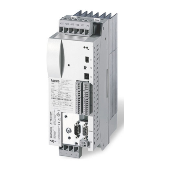
Lenze ECSCS Series Operating Instructions Manual (484 pages)
Axis module Speed & Torque
Brand:
Lenze
| Category:
Control Unit
| Size: 3 MB
Table of Contents
Table of Contents
5
1 Preface and General Information
12
About These Operating Instructions
12
Terminology Used
13
Code Descriptions
14
Signal Types and Scaling
15
Features of the Ecsxs Axis Module
16
Scope of Supply
17
Legal Regulations
18
2 Safety Instructions
19
General Safety and Application Notes for Lenze Controllers
19
Thermal Motor Monitoring
23
Forced Ventilated or Naturally Ventilated Motors
24
Self−Ventilated Motors
25
Residual Hazards
27
Safety Instructions for the Installation According to UL
29
Notes Used
30
3 Technical Data
31
General Data and Operating Conditions
31
Rated Data
33
Current Characteristics
35
Increased Continuous Current Depending on the Control Factor
35
Device Protection by Current Derating
38
4 Mechanical Installation
39
Important Notes
39
Mounting with Fixing Rails (Standard Installation)
40
Dimensions
40
Mounting Steps
41
Mounting with Thermal Separation (Push−Through Technique)
42
Dimensions
43
Mounting Steps
45
Mounting in Cold−Plate Design
46
Dimensions
47
Mounting Steps
48
5 Electrical Installation
49
Installation According to EMC (Installation of a Ce−Typical Drive System)
49
Power Terminals
52
Connection to the DC Bus (+UG, −UG)
55
Connection Plan for Mimimum Wiring with Internal Brake Resistor
57
Connection Plan for Mimimum Wiring with External Brake Resistor
59
Motor Connection
61
Motor Holding Brake Connection
62
Connection of an Ecsxk
64
Control Terminals
65
Digital Inputs and Outputs
69
Analog Input
70
Safe Torque off
71
Automation Interface (AIF)
80
Wiring of System Bus (CAN)
81
Wiring of the Feedback System
86
Resolver Connection
87
Encoder Connection
88
Digital Frequency Input/Output (Encoder Simulation)
91
6 Commissioning
93
Before You Start
93
Commissioning Steps (Overview)
94
Carrying out Basic Settings with GDC
95
Loading the Lenze Setting
97
Setting of Mains Data
98
Selecting the Function of the Charging Current Limitation
98
Setting the Voltage Thresholds
99
Entry of Motor Data for Lenze Motors
100
Holding Brake Configuration
102
Setting of the Feedback System for Position and Speed Control
103
Resolver as Position and Speed Encoder
104
Ttl/Sincos Encoder as Position and Speed Encoder
106
Ttl/Sincos Encoder as Position Encoder and Resolver as Speed Encoder
109
Absolute Value Encoder as Position and Speed Encoder
113
Absolute Value Encoder as Position Encoder and Resolver as Speed Encoder
117
Configuring the Digital Inputs and Outputs
121
Selecting the Operating Mode/Control Structure
126
Entry of Machine Parameters
141
Setpoint Selection
142
Controller Enable (CINH = 0)
143
Quick Stop (QSP)
144
Operation with Motors from Other Manufacturers
145
Optimising the Drive Behaviour after Start
154
7 Parameter Setting
161
General Information
161
Parameter Setting with "Global Drive Control" (GDC)
162
Parameter Setting with the XT EMZ9371BC Keypad
163
Connecting the Keypad
163
Description of the Display Elements
164
Description of the Function Keys
166
Changing and Saving Parameters
167
8 Configuration
168
Configuring Motionbus/System Bus (CAN)
169
Setting CAN Node Address and Baud Rate
169
Individual Addressing
173
Defining Boot−Up Master in the Drive System
175
Setting of Boot−Up Time/Cycle Time
176
Executing a Reset Node
178
Axis Synchronisation (CAN Synchronisation)
179
Monitoring of the Synchronisation (Sync Time Slot)
181
Axis Synchronisation Via CAN
182
Axis Synchronisation Via Terminal X6/DI1
183
Node Guarding
184
CAN Management
186
Diagnostics Codes
187
CAN Bus Status (C0359)
187
CAN Telegram Counter (C0360)
188
CAN Bus Load (C0361)
189
Remote Parameterisation (Gateway Function)
190
9 Monitoring Functions
192
Fault Responses
193
Overview of Monitoring Functions
194
Configuring Monitoring Functions
198
Monitoring Times for Process Data Input Objects
198
Time−Out Monitoring for Activated Remote Parameterisation
200
Short Circuit Monitoring (OC1)
201
Earth Fault Monitoring (OC2)
201
Motor Temperature Monitoring (OH3, OH7)
202
Heatsink Temperature Monitoring (OH, OH4)
204
Monitoring of Internal Device Temperature (OH1, OH5)
205
Function Monitoring of Thermal Sensors (H10, H11)
206
Current Load of Controller (I X T Monitoring: OC5, OC7)
207
Current Load of Motor (I2 X T Monitoring: OC6, OC8)
210
DC−Bus Voltage Monitoring (OU, LU)
214
Voltage Supply Monitoring − Control Electronics (U15)
217
Motor Phase Failure Monitoring (LP1)
217
Monitoring of the Resolver Cable (Sd2)
218
Motor Temperature Sensor Monitoring (Sd6)
219
Monitoring of the Absolute Value Encoder Initialisation (Sd7)
220
Sin/Cos Signal Monitoring (Sd8)
221
Monitoring of the Speed System Deviation (Nerr)
222
Monitoring of Max. System Speed (NMAX)
223
Monitoring of the Rotor Position Adjustment (PL)
224
10 Diagnostics
225
Diagnostics with Global Drive Control (GDC)
225
Diagnostics with Global Drive Oscilloscope (GDO)
226
GDO Buttons
227
Diagnostics with the XT EMZ9371BC Keypad
228
Diagnostics with Pcan−View
229
Monitoring of Telegram Traffic on the CAN Bus
229
Setting All CAN Nodes to the "Operational" Status
231
11 Troubleshooting and Fault Elimination
232
Fault Analysis
232
Fault Analysis Via the LED Display
232
Fault Analysis with Keypad XT EMZ9371BC
232
Fault Analysis with the History Buffer
233
Fault Analysis Via LECOM Status Words (C0150/C0155)
235
Malfunction of the Drive
237
Fault Messages
238
Causes and Remedies
238
Reset Fault Messages (TRIP−RESET)
246
12 Function Library
247
AIF (Automation Interface Management)
247
Aif1In
248
Aif1Out
251
Aif2In
256
Aif2Out
258
Aif3In
261
Aif3Out
263
Ain1
266
CAN (CAN Management)
267
Cansync (CAN Bus Synchronisation)
270
Can1In
273
Can1Out
276
Can2In
282
Can2Out
285
Can3In
288
Can3Out
291
Dctrl
294
Quick Stop (QSP)
297
Operation Inhibit (DISABLE)
297
Controller Inhibit (CINH)
297
Setting TRIP (TRIP−SET)
298
Resetting TRIP (TRIP−RESET)
298
Axis Module Status
299
DFIN (Master Frequency Input)
301
DFOUT (Master Frequency Output)
304
Digin (Freely Assignable Digital Inputs)
307
Digout (Freely Assignable Digital Outputs)
308
FCODE (Free Codes)
309
FIXED (Output of Constant Signals)
312
Inneg
313
Outneg
315
Sys
317
Speed (Speed Control)
318
Changing the Direction of Rotation
325
Setpoint Processing
326
Setting of Motor Control
332
Holding Brake Control
340
Torque (Torque Control)
343
Torque Control with Speed Limitation
349
Changing the Direction of Rotation
350
Setpoint Processing
351
Setting of Motor Control
354
Holding Brake Control
360
13 Appendix
363
Code Table
363
Selection Lists for Signal Linking
428
List of the Digital Signal Sources
428
List of the Analog Signal Sources
437
List of the Phase Signal Sources
440
General Information about the System Bus (CAN)
441
Communication with Motionbus/System Bus (CAN)
442
Structure of the CAN Data Telegram
442
Communication Phases of the CAN Network (NMT)
444
Process Data Transfer
447
Parameter Data Transfer
454
Addressing of the Parameter and Process Data Objects
460
Overview of Accessories
462
Connector Sets
462
Shield Mounting Kit
462
Components for Operation and Communication
463
Brake Resistor
464
Mains Fuses
466
Mains Chokes
467
RFI Filters
468
14 Index
469
Advertisement
Lenze ECSCS Series Mounting Instructions (214 pages)
Axis module in cold plate design
Brand:
Lenze
| Category:
Servo Drives
| Size: 1 MB
Table of Contents
Deutsch
7
Table of Contents
7
1 Über diese Dokumentation
8
2 Sicherheitshinweise
9
Allgemeine Sicherheits− und Anwendungshinweise für Lenze−Antriebsregler
9
Motor Thermisch Überwachen
13
Fremdbelüftete oder Selbstgekühlte Motoren
15
Eigenbelüftete Motoren
17
Restgefahren
20
Sicherheitshinweise für die Installation nach UL/CSA
22
3 Technische Daten
24
Allgemeine Daten und Einsatzbedingungen
24
Bemessungsdaten
27
4 Mechanische Installation
29
Wichtige Hinweise
29
Montage in Cold−Plate−Technik
30
Abmessungen
31
Montageschritte
32
5 Elektrische Installation
33
Emv−Gerechte Installation (Aufbau des Ce−Typischen Antriebssystems)
33
Leistungsanschlüsse
36
Anschluss an den DC−Zwischenkreis (+UG, −UG)
40
Anschluss Motor
43
Anschluss Motorhaltebremse
44
Steueranschlüsse
46
Digitale Eingänge und Ausgänge
50
Analog−Eingang
51
Sicher Abgeschaltetes Moment
53
Systembus (CAN) Verdrahten
59
Rückführsystem Verdrahten
63
Anschluss Resolver
64
Anschluss Encoder
65
Leitfrequenzeingang/−Ausgang (Encoder−Nachbildung)
69
6 Installation Überprüfen
72
English
77
1 About this Documentation
78
2 Safety Instructions
79
General Safety and Application Notes for Lenze Controllers
79
Thermal Motor Monitoring
83
Forced Ventilated or Naturally Ventilated Motors
85
Self−Ventilated Motors
87
Residual Hazards
90
Safety Instructions for the Installation According to UL
92
3 Technical Data
94
General Data and Operating Conditions
94
Rated Data
97
4 Mechanical Installation
99
Important Notes
99
Mounting in Cold−Plate Design
100
Dimensions
101
Mounting Steps
102
5 Electrical Installation
103
Installation According to EMC (Installation of a Ce−Typical Drive System)
103
Power Terminals
106
Connection to the DC Bus (+UG, −UG)
110
Motor Connection
114
Motor Holding Brake Connection
115
Control Terminals
117
Digital Inputs and Outputs
121
Analog Input
122
Safe Torque off
124
Wiring of System Bus (CAN)
130
Wiring of the Feedback System
134
Resolver Connection
135
Encoder Connection
136
Digital Frequency Input/Output (Encoder Simulation)
140
6 Installation Check
143
Français
147
1 Présentation du Document
148
2 Consignes de Sécurité
149
Consignes Générales de Sécurité Et D'utilisation Relatives Aux Variateurs Lenze
149
Surveillance de la Température du Moteur
153
Moteurs Avec Motoventilation Ou Refroidissement Naturel
155
Moteurs Avec Autoventilation
157
Dangers Résiduels
160
Consignes de Sécurité Pour L'installation Selon UL
162
3 Spécifications Techniques
164
Caractéristiques Générales Et Conditions D'utilisation
164
Caractéristiques Assignées
167
4 Installation Mécanique
169
Remarques Importantes
169
Montage Sur Semelle de Refroidissement
170
Cotes
171
Opérations de Montage
172
5 Installation Électrique
174
Câblage Conforme CEM (Installation D'un Système D'entraînement CE)
174
Partie Puissance
177
Raccordement du Bus CC (+UG, −UG)
181
Raccordement du Moteur
184
Raccordement du Frein de Parking
185
Partie Commande
187
Entrées Et Sorties Numériques
191
Entrée Analogique
192
Absence Sûre de Couple
194
Câblage du Bus Système (CAN)
200
Câblage du Système de Bouclage
204
Raccordement du Résolveur
205
Raccordement du Codeur
206
Entrée/Sortie Fréquence Maître (Émulation Codeur)
210
6 Vérification de L'installation
213
Advertisement
Related Products
Lenze ECSCP Series
Lenze ECSCM Series
Lenze ECSCA Series
Lenze ECS 004 Series
Lenze ECS 016 Series
Lenze ECS 032 Series
Lenze ECSD 064 Series
Lenze ECSD 008 Series
Lenze ECSE 048 Series
Lenze ECSE 032 Series
Lenze Categories
DC Drives
Control Unit
Inverter
Engine
Controller
More Lenze Manuals
Login
Sign In
OR
Sign in with Facebook
Sign in with Google
Upload manual
Upload from disk
Upload from URL