Lenze ECS series Operating Instructions Manual
Axis module ˘ "motion" application
Hide thumbs
Also See for ECS series:
- Operating instructions manual (484 pages) ,
- Mounting instructions (200 pages) ,
- Operating instructions manual (40 pages)

Related Manuals for Lenze ECS series


Summary of Contents for Lenze ECS series
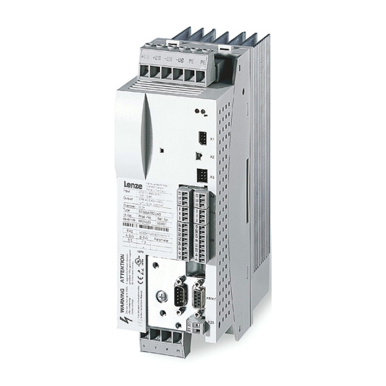
- Page 1 EDBCSXM064 .6Rc Operating Instructions ECSEMxxx / ECSDMxxx / ECSCMxxx Axis module ˘ "Motion" application...
- Page 2 0Fig. 0Tab. 0 © 2007 Lenze Drive Systems GmbH, Hans−Lenze−Straße 1, D−31855 Aerzen No part of this documentation may be reproduced or made accessible to third parties without written consent by Lenze Drive Systems GmbH. All information given in this documentation has been selected carefully and complies with the hardware and software described.
- Page 3 ECSEA_003A EDBCSXM064 EN 7.0...
- Page 4 Scope of supply Position Description Quantity ECSLM... axis module Accessory kit with fixing material corresponding to the design (L): "E" − standard panel−mounted unit "D" − push−through technique "C" − cold−plate technique Mounting Instructions Drilling jig Functional earth conductor (only ECSDM...) Note! The ECSZA000X0B connectors must be ordered separately.
-
Page 5: Table Of Contents
............General safety and application notes for Lenze controllers . - Page 6 ....... . . Entry of motor data for Lenze motors .
- Page 7 Contents Configuration of control interface (control and status word) ....6.8.1 Process data to the axis module ....... . . 6.8.2 Process data from the axis module .
- Page 8 Contents Configuration ............. General information about the system bus (CAN) .
- Page 9 Contents Troubleshooting and fault elimination ........10.1 Fault analysis .
-
Page 10: Preface And General Information
Terminology used Term In the following text used for Power supply ECSxE... power supply module module ECSxE... Any power supply module of ECS series Capacitor module ECSxK... capacitor module ECSxK... Any capacitor module of ECS series Axis module ECSxM... axis module Controller ECSxS... -
Page 11: Code Descriptions
Preface and general information Code descriptions Code descriptions Lenze codes are described in the form of tables with the following structure: Column Abbreviation Meaning Cxxxx Code no. Cxxxx Subcode 1 of Cxxxx Subcode 2 of Cxxxx Changed parameter of the code or subcode is accepted after pressing T... -
Page 12: Features Of The Axis Module Ecsxm
Supported feedback systems: ƒ – Resolver with and without position storage – Encoder (incremental encoder (TTL encoder), sin/cos absolute value encoder) Commissioning and parameter setting with the Lenze parameter setting and ƒ operating program "Global Drive Control" (GDC) EDBCSXM064 EN 7.0... -
Page 13: Structure
Structure UG+ UG- UG+ UG- PE PE ECSxM Digital_IO Drive control C0135 C0576 C3160 C3161 C0579 C3002 Init C3152 C3162 C3008 C3009 C3153 C3010 C3011 Stand by C3012 C3020 Control word CAN_IO ManJog Trouble C3021 C3022 Toggle bit C3037 C3038 Monitor data VelMode IP-Mode... -
Page 14: Scope Of Supply
Preface and general information Scope of supply Scope of supply The scope of supply of the ECSxM... axis module contains: Basic device ƒ Accessory kit with fixing material corresponding to the design: ƒ – "E" − standard panel−mounted unit – "D" − push−through technique –... -
Page 15: Legal Regulations
The specifications, processes and circuitry described in these instructions are for guidance only and must be adapted to your own specific application. Lenze does not take responsibility for the suitability of the process and circuit proposals. -
Page 16: Safety Instructions
General safety and application notes for Lenze controllers (According to: Low−Voltage Directive 73/23/EEC) General Depending on their degree of protection, some parts of Lenze controllers (frequency inverters, servo inverters, DC controllers) and their accessory components can be live, moving and rotating during operation. Surfaces can be hot. - Page 17 Reduce housing openings and cutouts to a minimum. Lenze controllers can cause a DC residual current in the protective conductor. If a residual current device (RCD) is used as a protective means in the case of direct or indirect contact, only a residual current device (RCD) of type B may be used on the current supply side of the controller.
- Page 18 Safety instructions General safety and application notes for Lenze controllers Safety functions Special controller variants support safety functions (e.g. "safe torque off", formerly "safe standstill") according to the requirements of Annex I No. 1.2.7 of the EC Directive "Machinery" 98/37/EC, EN 954−1 Category 3 and EN 1037. Strictly observe the notes on the safety functions given in the documentation on the respective variants.
-
Page 19: Residual Hazards
ECSXE power supply module and the input ƒ current limitation is activated depending on the DC bus voltage (C0175 = 1 or 2). the axis module is not supplied via a power supply module from Lenze. ƒ the low−voltage supply (24 V) is switched off. - Page 20 Motor protection Only use motors with a minimum insulation resistance of û = 1.5 kV, ƒ min. du/dt = 5 kV/ms. – Lenze motors meet these requirements. When using motors with an unknown insulation resistance, please contact your ƒ motor supplier.
-
Page 21: Safety Instructions For The Installation According To Ul Or Ur
Safety instructions Safety instructions for the installation according to U or U Safety instructions for the installation according to U or U Warnings! General markings: Use 60/75 °C or 75 °C copper wire only. ƒ Maximum ambient temperature 55 °C, with reduced output current. ƒ... -
Page 22: Definition Of Notes Used
Safety instructions Definition of notes used Definition of notes used The following pictographs and signal words are used in this documentation to indicate dangers and important information: Safety instructions Structure of safety instructions: Danger! (characterises the type and severity of danger) Note (describes the danger and gives information about how to prevent dangerous situations) -
Page 23: Technical Data
Technical data General data and operating conditions Technical data General data and operating conditions Standards and operating conditions Conformity Low−Voltage Directive (73/23/EWG) Approvals UL 508C Power conversion equipment Underwriter Laboratories (File No. E132659) for USA and Canada Max. permissible shielded 50 m For rated mains voltage and switching frequency of 8 kHz motor cable length... - Page 24 Technical data General data and operating conditions General electrical data Compliance with EN 61800−3 Noise emission Compliance with limit value class A to EN 55011 (achieved with application−typical collective filter) Noise immunity Requirements to EN 61800−3 Requirements Standard Severity EN 61000−4−2 3, i.
-
Page 25: Rated Data
Technical data Rated data Rated data Rated data Type Axis module ECSxL004 ECSxL008 ECSxL016 Output power 400 V mains [kVA] Data for operation with upstream supply module on mains mains voltage DC−bus voltage 15 ... 770 DC bus DC−bus current DC bus Rated output current at 4 kHz (causes a heatsink temperature of 70°C at an ambient... - Page 26 Technical data Rated data Rated data Type Axis module ECSxL004 ECSxL008 ECSxL016 Output power 400 V mains [kVA] 11.2 13.2 Data for operation with upstream supply module on mains mains voltage DC−bus voltage 15 ... 770 DC bus DC−bus current 15.6 12.5 20.9...
-
Page 27: Current Characteristics
Technical data Current characteristics Increased continuous current depending on the control factor Current characteristics 3.3.1 Increased continuous current depending on the control factor In the lower speed range ˘ the motor does not need the full motor voltage ˘ particularly the more powerful ECS axis modules can be permanently operated with increased output ^ 25). - Page 28 Technical data Current characteristics Increased continuous current depending on the control factor The following table represents the connections between mains voltage, DC−bus voltage and motor voltage: Mains voltage DC−bus voltage Output voltage (motor voltage) nominally achievable for 100 % x 1.35] mains mains modulation...
- Page 29 Technical data Current characteristics Increased continuous current depending on the control factor Example: The ECS axis module suitable for operation in conjunction with a Lenze motor of type MCS 14L32 is to be determined. Rated motor data ƒ – Rated motor torque (M ) = 17.2 Nm...
-
Page 30: Device Protection By Current Derating
Technical data Current characteristics Device protection by current derating 3.3.2 Device protection by current derating The maximum output current is limited. With output frequencies < 5 Hz the limitation depends on the heatsink temperature. ‚ 1.00 1.00 £ 70 °C ... -
Page 31: Mechanical Installation
– Ensure unimpeded ventilation of cooling air and outlet of exhaust air. – Several modules of the ECS series can be installed in the control cabinet next to each other without any clearance. The mounting plate of the control cabinet ƒ... -
Page 32: Mounting With Fixing Rails (Standard Installation)
Mechanical installation Mounting with fixing rails (standard installation) Dimensions Mounting with fixing rails (standard installation) 4.2.1 Dimensions Note! Mounting with ECSZS000X0B shield mounting kit: Mounting clearance below the module > 195 mm ƒ ECSxA005 Fig.4−1 Dimensions for "panel−mounted" design Axis module Dimensions [mm] Type Size... -
Page 33: Assembly Steps
Mechanical installation Mounting with fixing rails (standard installation) Assembly steps 4.2.2 Assembly steps How to install the axis module: 1. Prepare the fixing holes on the mounting surface. – Use the drilling jig for this purpose. 2. Take the fixing rails from the accessory kit in the cardboard box. 3. -
Page 34: Mounting With Thermal Separation (Push−Through Technique)
Mechanical installation Mounting with thermal separation (push−through technique) Mounting with thermal separation (push−through technique) For the push−through technique the rear panel of the control cabinet must be a steel plate with a thickness of at least 2 mm. The edges of the mounting cutout and the fixing holes for the clamps must be slightly curved inwards (towards the axis module). -
Page 35: Dimensions
Mechanical installation Mounting with thermal separation (push−through technique) Dimensions 4.3.1 Dimensions Note! Mounting with ECSZS000X0B shield mounting kit: Mounting clearance below the module > 195 mm ƒ ECSXA007 Fig.4−2 Dimensions for "push−through design" Mounting cutout (a1 x b1), ^ 36 Axis module Dimensions [mm] Type... - Page 36 Mechanical installation Mounting with thermal separation (push−through technique) Dimensions Dimensions of mounting cutout Note! Mounting with shield mounting kit ECSZS000X0B001: Clearance below the mounting cutout > 220 mm ƒ ECSXA063 Fig.4−3 Dimensions of mounting cutout Mounting surface Mounting cutout for size 0 Mounting cutout for size 1 Axis module Dimensions [mm]...
-
Page 37: Assembly Steps
Mechanical installation Mounting with thermal separation (push−through technique) Assembly steps 4.3.2 Assembly steps How to mount the axis module: 1. Prepare the fixing holes for the wire clamps on the mounting area. – For this purpose, apply a drilling jig. 2. -
Page 38: Mounting In Cold−Plate Design
Mechanical installation Mounting in cold−plate design Mounting in cold−plate design The axis modules ECSC... are intended for mounting in cold−plate design (e.g. on collective coolers). Requirements for collective coolers The following requirements must be met to ensure a safe operation of the axis modules: Good thermal contact with the cooler ƒ... -
Page 39: Dimensions
Mechanical installation Mounting in cold−plate design Dimensions 4.4.1 Dimensions Note! Mounting with ECSZS000X0B shield mounting kit: Mounting clearance below the module > 195 mm ƒ ECSXA009 Fig.4−5 Dimensions for "cold−plate design" Axis module Dimensions [mm] Type Size ECSCM004 ECSCM008 88.5 ECSCM016 ECSCM032 ECSCM048... -
Page 40: Assembly Steps
Mechanical installation Mounting in cold−plate design Assembly steps 4.4.2 Assembly steps À Á Â ECSXA030 Fig.4−6 Mounting for "cold−plate design" Proceed as follows to mount the axis module: 1. Prepare the fixing holes on the mounting plate. – Use a drilling jig for this purpose. 2. -
Page 41: Electrical Installation
Electrical installation Installation according to EMC (installation of a CE−typical drive system) Electrical installation Installation according to EMC (installation of a CE−typical drive system) General information The electromagnetic compatibility of a machine depends on the type of installation ƒ and care taken. Especially consider the following: –... - Page 42 Electrical installation Installation according to EMC (installation of a CE−typical drive system) Structure Connect the power supply modules, capacitor modules (optional), axis modules, RFI ƒ filters, and mains chokes to the earthed mounting plate with a surface as large as possible.
- Page 43 Electrical installation Installation according to EMC (installation of a CE−typical drive system) Shielding Connect the motor cable shield to the axis module ƒ – with the ECSZS000X0B shield mounting kit. – extensively to the mounting plate below the axis module. –...
-
Page 44: Power Terminals
Electrical installation Power terminals Power terminals ECSXA080 Fig.5−1 Plug connectors for power terminals Danger! Dangerous voltage The discharge current to earth (PE) is > 3.5 mA AC or > 10 mA DC. Possible consequences: Death or severe injuries when the device is touched in the event of a fault. ƒ... - Page 45 Electrical installation Power terminals All power connections are plug connections and are coded. The ECSZA000X0B ƒ connectors must be ordered separately. Installation of the cables according to EN 60204−1. ƒ The cables used must comply with the approvals required at the site of use (e.g. VDE, ƒ...
- Page 46 Electrical installation Power terminals Shielded cables The following factors decisively determine the effect of the shielded cables: Good shield connection ƒ – Ensure a contact surface as large as possible Low shield resistance ƒ – Only use shields with tin−plated or nickel−plated copper braids (shields with steel braids cannot be used).
-
Page 47: Connection To The Dc Bus (+Ug, −Ug)
Electrical installation Power terminals Connection to the DC bus (+U , −U 5.2.1 Connection to the DC bus (+U , −U Stop! No device protection for voltage surges of the DC bus In passive axis modules (without 24 V supply) the charging connection can be overloaded by voltage surges of the DC bus. - Page 48 When ECS axis modules are supplied by devices of the 82xx and 93xx series with a ƒ continuous DC current > 40 A, install the following fuses between the supplying device and the ECS devices: Fuse Support Value [A] Lenze type Lenze type EFSGR0500ANIN EFH20007 Warnings! Use UL−approved cables, fuses and fuse holders only. ƒ...
-
Page 49: Connection Plans
Electrical installation Power terminals Connection plans 5.2.2 Connection plans Observe... the notes in the detailed documentation of the power supply module. Mimimum wiring with power supply module ECSEE... / ECSDE... A brake resistor is integrated in the ECSEE... and ECSDE... power supply modules. The internal brake resistor is used with the following jumpers: from X22/BR0 to X22/+UG ƒ... - Page 50 Electrical installation Power terminals Connection plans Mimimum wiring with power supply module ECSCE... Based on the design, the ECSCE... power supply module is not provided with an integrated brake resistor. For this reason, install an external brake resistor of the ERBM..., ERBS... or ERBD...
-
Page 51: Motor Connection
) when using synchronous motors or according to the rated motor current ) for asynchronous motors. Length of the unshielded ends: 40 ... 100 mm (depending on the cable cross−section) ƒ Lenze system cables meet these requirements. ƒ Use the ECSZS000X0B shield mounting kit for EMC−compliant wiring. ƒ... -
Page 52: Motor Holding Brake Connection
Electrical installation Power terminals Motor holding brake connection 5.2.4 Motor holding brake connection The motor holding brake is connected to X25/BD1 and X25/BD2 ƒ and is supplied with low voltage via the terminals X6/B+ and X6/B−: ƒ +23 ... +30 V DC, max.1.5 A Stop! Protect X6/B+ with an F 1.6 A fuse. - Page 53 Electrical installation Power terminals Motor holding brake connection 5.2.4.3 Requirements on the brake cables Use Lenze system cable with integrated brake cable. ƒ – The shielding of the brake cable must be separated. Length: max. 50 m ƒ If a separately installed brake cable is required, lay it in a shielded manner.
-
Page 54: Connection At Capacitor Module Ecsxk
Electrical installation Power terminals Connection at capacitor module ECSxK... (optional) 5.2.5 Connection at capacitor module ECSxK... (optional) Observe... the notes in the detailed documentation of the capacitor module. F1...F3 " " ECSxK... ECSxE... ECSxS/P/M/A... BD1 BD2 U V W PE "... -
Page 55: Control Terminals
Electrical installation Control terminals Control terminals ECSXA070 Fig.5−7 Plug connectors for control terminals (X6) For the supply of the control electronics an external 24 V DC voltage at terminals X6/+24 and X6/GND is required. Stop! The control cables must always be shielded to prevent interference ƒ... - Page 56 Electrical installation Control terminals L3 PE +UG +UG ECSxE... ECSxS/P/M/A... " " " " " " " +24 VDC 24 VDC ECSXA013 Fig.5−8 System: control signals with internal brake resistor " HF−shield termination by large−surface connection to functional earth (see Mounting Instructions for ECSZS000X0B shield mounting kit) Contactor relay Voltage supply of motor holding brake 23 ...
- Page 57 Electrical installation Control terminals Cable cross−sections and screw−tightening torques Cable type Wire end ferrule Cable cross−section Starting torque Stripping length 0.08 ... 1.5 mm Without wire end ferrule (AWG 28 ... 16) 0.22 ... 0.25 Nm flexible 5 mm (1.95 ... 2.2 lb−in) Insulated with wire end 0.25 ...
-
Page 58: Digital Inputs And Outputs
Electrical installation Control terminals Digital inputs and outputs 5.3.1 Digital inputs and outputs Stop! If an inductive load is connected to X6/DO1, a spark suppressor with a limiting function to max. 50 V ± 0 % must be provided. GNDext DI1 DI2 DI3 DI4 "... -
Page 59: Analog Input
Electrical installation Control terminals Analog input 5.3.2 Analog input " " ECSXA015 Fig.5−10 Analog input at X6 " HF−shield termination by large−surface connection to functional earth (see Mounting Instructions for ECSZS000X0B shield mounting kit) Analog input configuration Set via C0034 whether the input is to be used for a master voltage or a master ƒ... -
Page 60: Safe Torque Off
Electrical installation Control terminals Safe torque off 5.3.3 Safe torque off The axis modules support the safety function "safe torque off" (formerly "safe standstill"), "protection against unexpected start−up", in accordance with the requirements of control category 3 of EN 954 part 1 and part 2 (from 01.01.2007: EN ISO 13849). For this purpose, the axis modules are provided with two independent safety paths. - Page 61 Electrical installation Control terminals Safe torque off 5.3.3.2 Functional description The "safe torque off" state can be initiated any time via the input terminals X6/SI1 (controller enable/inhibit) and X6/SI2 (pulse enable/inhibit). For this purpose a LOW level has to be applied at both terminals: X6/SI1 = LOW (controller inhibited): ƒ...
- Page 62 Electrical installation Control terminals Safe torque off 5.3.3.3 Additional safety instructions Installation/commissioning Only qualified personnel is permitted to install and set up the "safe torque off" ƒ function. All control components (switches, relays, PLC, ...) and the control cabinet must ƒ...
- Page 63 Electrical installation Control terminals Safe torque off 5.3.3.4 Technical data Terminal assignment Plug connector X6 Terminal Function Level Electrical data X6/S24 Low−voltage supply 18 ... 30 V DC 0.7 A X6/SO "Safe torque off" feedback 24 V DC During operation output 0.7 A (max.
- Page 64 Electrical installation Control terminals Safe torque off 5.3.3.5 Minimum wiring In order to reach the control category 3, the signal at X6/SO must be verified additionally. This requires external wiring. The external wiring must be adapted to the existing safety concepts and checked for a correct operation.
- Page 65 Electrical installation Control terminals Safe torque off Requirements for external wiring with multiple−contact switches: The switches S1 and S2 must have at least three contacts: ƒ – At least one NC contact and two NO contacts being all electrically independent and positively driven.
- Page 66 Electrical installation Control terminals Safe torque off "Safe torque off" with safety PLC The version "safe torque off" with safety PLC must ensure the functions of the multiple−contact switches. The following conditions must be fulfilled: The NO contacts only close after the NC contacts are open. ƒ...
- Page 67 Electrical installation Control terminals Safe torque off 5.3.3.6 Function check After installation the operator must check the "safe torque off" function. ƒ The function check must be repeated at regular intervals, after one year at the ƒ latest. Stop! If the function check leads to impermissible states at the terminals, commissioning cannot take place! Test specifications Check the circuitry with regard to correct function.
- Page 68 Electrical installation Control terminals Safe torque off 5.3.3.7 Example: Wiring with electronic safety control unit for category 3 ECSXA102 Fig.5−13 Example: Wiring with "Siemens 3TK2842"safety control unit T1 Test key 1 T2 Test key 2 The motor is shutdown in accordance with stop category 1 of EN 60204 when the ƒ...
-
Page 69: Automation Interface (Aif)
A communication module can be plugged on or removed from the automation interface (X1). This can also be done during operation. Various communication modules are available for supply modules and axis modules of the ECS series: Communication module Type/order number... -
Page 70: Wiring Of Motionbus/System Bus (Can)
Electrical installation Wiring of MotionBus/system bus (CAN) Wiring of MotionBus/system bus (CAN) Basic wiring of the CAN buses The two following schematic diagrams show drive systems with different master value concepts: In Fig.5−14 a higher−level control takes over the function of the master, e. g. ETC. ƒ... - Page 71 Electrical installation Wiring of MotionBus/system bus (CAN) ECS_COB003 Fig.5−16 Bus connections on the controller Assignment of the plug connectors X4 (CAN) X14 (CAN−AUX) Description CAN−HIGH CAN−LOW Reference potential Specification of the transmission cable For the use of the transmission cable, follow our recommendations: Specification of the transmission cable £...
- Page 72 Electrical installation Wiring of MotionBus/system bus (CAN) Wiring of the MotionBus (CAN) ECS_COB004 Fig.5−17 Example of wiring the MotionBus (CAN) ECS axis module Higher−level control, e. g. ETC Note! Respectively connect one bus terminating resistor (120 W) to the first and the last node of the MotionBus (CAN) / system bus (CAN).
- Page 73 Electrical installation Wiring of MotionBus/system bus (CAN) Bus cable length Note! Be absolutely sure to observe the permissible cable lengths. 1. Check the compliance with the total cable length in Tab. 5−1. The total cable length is defined by the baud rate. Baud rate [kBit/s] Max.
-
Page 74: Wiring Of The Feedback System
(e.g. by using separating webs or separated draglines) is not ensured on the entire cable length cable due to an installation on the system side, the encoder cable must be provided with an insulation resistance of 300 V. Lenze encoder cables meet this requirement. -
Page 75: Encoder Connection
Electrical installation Wiring of the feedback system Encoder connection Æ +REF -REF +COS -COS +SIN 0.14 -SIN R1 (+KTY) R2 (-KTY) ECSXA022 Fig.5−18 Resolver connection Assignment of socket connector X7: Sub−D 9−pole Signal +Ref −Ref +COS −COS +SIN −SIN (+KTY) (−KTY) 0.5 mm 0.14 mm... - Page 76 Electrical installation Wiring of the feedback system Encoder connection Via the 9−pole Sub−D−plug X8, you can connect the following encoders: Incremental encoder ƒ – with two 5 V complementary signals (TTL encoders) that are electrically shifted by 90°. – Optionally, the zero track can be connected. Sin/cos encoder ƒ...
- Page 77 Electrical installation Wiring of the feedback system Encoder connection Incremental encoder (TTL encoder) Features Input/output frequency: 0 ... 200 kHz Current consumption: 6 mA per channel Current on output V (X8/pin 4): Max. 200 mA < 50 m R1 (+KTY) R2 (-KTY) ECSXA026 Fig.5−19...
- Page 78 Electrical installation Wiring of the feedback system Encoder connection SinCos encoder Features Input/output frequency: 0 ... 200 kHz 221 W Internal resistance (R Offset voltage for signals SIN, COS, Z: 2.5 V The differential voltage between signal track and reference track must not exceed ƒ...
-
Page 79: Commissioning
Commissioning Before you start Note! In the description of the commissioning steps the use of a Lenze motor is ƒ assumed. For details on the operation with other motors see ^ 144. The operation with the Lenze parameter setting and operating program ƒ... -
Page 80: Commissioning Steps (Overview)
Commissioning Commissioning steps (overview) Commissioning steps (overview) Start Carry out the basic setting (^ 81) Set homing (^ 83) Optimise drive behaviour (^ 152) Save parameters in the drive with C0003 = 1. Save parameter set with GDC in the parameter set file. EDBCSXM064 EN 7.0... -
Page 81: Basic Settings With Gdc
C0175 (function of the charge relay) – For operation with power supply module ECSxE set C0175 = 3. ^ 89 Enter motor data. Lenze motors: Use the motor assistant of the GDC. ^ 144 Motors of other manufacturers ^ 91 Configure holding brake. - Page 82 Commissioning Commissioning steps (overview) Basic settings with GDC Setting Short description Detailed information ^ 110 11. Enter machine parameters. Set the following codes in the GDC parameter menu under Motion W Machine parameter: C0011 (max. speed) C0105 (deceleration time for quick stop (QSP)) C0596 (max.
-
Page 83: Setting Of Homing
Commissioning Commissioning steps (overview) Setting of homing 6.2.2 Setting of homing Homing By means of homing, the definition of the measuring system in the machine is effected, and therefore also the definition of the zero position within the traversing range that is physically possible. - Page 84 If this is not the case, set the operating mode manually (step 3 A). If the value from C5000 has not been written into C5001 after repeating step 3 A), please contact Lenze! ^ 139 Enable controller. The controller can only be enabled via a master control.
- Page 85 C5000 into C5001 (here C5001 = 7). If this is not the case, repeat step 6 A. If the setting from C5000 has not been transferred to C5001 after repeating step 6 A, please contact Lenze! ^ 104 Start travel according to the The master control sets the control bit 12 = 1 (TRUE).
-
Page 86: Loading The Lenze Setting
Loading the Lenze setting Loading the Lenze setting Note! If an axis module with the "Motion" application software is reset to the Lenze setting, previous settings get lost (mains and motor data, feedback system settings, CAN node addresses)! The GDC contains the parameters or codes to be set in the parameter menu under... -
Page 87: Setting Of Mains Data
DC bus is loaded in a controlled way. Therefore, set C0175 = 3 for the axis module. If the Lenze setting has been loaded via C0002, C0175 = 3 must be reset. Cyclic connection and disconnection of the mains voltage of the power ƒ... -
Page 88: Setting The Voltage Thresholds
[V AC] [V DC] [V DC] yes/no yes/no 400 ... 460 yes/no yes/no C0174 C0174 + 5 V 400 (Lenze setting) yes/no C0174 C0174 + 5 V 400 ... 460 yes/no C0174 C0174 + 5 V C0174 C0174 + 5 V... -
Page 89: Entry Of Motor Data For Lenze Motors
The following only describes the parameter setting for Lenze motors! (For ƒ operation with motors of other manufacturers see: ^ 144) If the Lenze setting has been loaded via C0002, the motor data must be ƒ re−entered. Parameter setting with the "Input assistant for motor data" of the GDC 1. - Page 90 Commissioning Entry of motor data for Lenze motors ECSXA302 Fig.6−7 GDC view: Motor selection 3. Select the connected motor from the list (see motor nameplate). – The corresponding motor data is displayed on the right in the "Motor data" fields.
-
Page 91: Holding Brake Configuration
Commissioning Holding brake configuration Holding brake configuration Tip! If you use a motor without a holding brake, you can skip this chapter. In the GDC, the parameters or codes to be set can be found in the parameter menu under Short setup W Brake. -
Page 92: Closing The Brake
Commissioning Holding brake configuration Closing the brake 6.6.1 Closing the brake Use control bit 7 = 0 (FALSE) to close the brake. CtrlWord.Bit7 At the same time the internal quick stop (QSP) is activated and the drive is braked to standstill within the deceleration time set in C0105 (NSet = 0). -
Page 93: Opening The Brake
Commissioning Holding brake configuration Opening the brake 6.6.2 Opening the brake Use control bit 7 = 1 (TRUE) to enable the CtrlWord.Bit7 controller. The control bit 9 is set to 0 (FALSE) at the same time (controller inhibit (CINH) is deactivated) and the torque defined in C0244 is created. -
Page 94: Setting Of The Feedback System For Position And Speed Control
ƒ Absolute value encoder (Hiperface®, single−turn/multi−turn) at X8 (¶ 98) ƒ Note! If the Lenze setting has been loaded via C0002, the feedback system must be reset. 6.7.1 Resolver for position and speed control If a resolver is connected to X7 and used for position and speed control, no settings are required. - Page 95 Commissioning Setting of the feedback system for position and speed control Codes for setting the resolver feedback Code Possible settings IMPORTANT Designation Lenze/ Selection {Appl.} ^ 94 [C0495] Feedback n Selection of feedback system for speed control Resolver at X7...
-
Page 96: Resolver As Absolute Value Encoder
(number of pole pairs > 1): 180° Max. rotation + " Number of pole pairs Code Possible settings IMPORTANT Designation Lenze/ Selection {Appl.} ^ 96 C3002 NoChangeOfP Resolver as absolute value encoder ChangeOfPos After "mains off/on", homing... -
Page 97: Incremental Encoder / Sin/Cos Encoder Without Serial Communication
Commissioning Setting of the feedback system for position and speed control Incremental encoder / sin/cos encoder without serial communication 6.7.4 Incremental encoder / sin/cos encoder without serial communication If an incremental encoder or a sin/cos encoder without serial communication is connected to X8 and used for position and speed control, comply with the following setting sequence: 1. -
Page 98: Absolute Value Encoder (Hiperface®, Single−Turn/Multi−Turn)
Commissioning Setting of the feedback system for position and speed control Absolute value encoder (Hiperface®, single−turn/multi−turn) 6.7.5 Absolute value encoder (Hiperface®, single−turn/multi−turn) Danger! For operating systems up to and including version 7.0: Uncontrolled movements of the drive possible when absolute value encoders are used! If an absolute value encoder is disconnected from the axis module during operation, a OH3−TRIP (fault no. - Page 99 Commissioning Setting of the feedback system for position and speed control Absolute value encoder (Hiperface®, single−turn/multi−turn) If an absolute value encoder with a Hiperface® interface is connected to X8 and is used for position and speed control, comply with the following setting sequence: 1.
-
Page 100: Codes For Setting The Encoder Feedback
The GDC contains the parameters or codes to be set in the parameter menu under Motor/Feedback W Feedback. ECSXA533 Fig.6−10 GDC view: Commissioning of further feedback systems Code Possible settings IMPORTANT Designation Lenze/ Selection {Appl.} ^ 149 C0058 Rotor diff −90.0 Rotor displacement angle for synchronous motors (C0095) {0.1 _} −180.0... - Page 101 {Appl.} ^ 97 [C0419] Enc. Setup Encoder selection ^ 98 Selection of encoder type indicated on the nameplate of the Lenze motor. The encoder data (C0420, C0421, C0427) is set automatically in accordance with the selection. Common IT512−5V Incremental encoder with TTL level IT1024−5V...
- Page 102 Commissioning Setting of the feedback system for position and speed control Codes for setting the encoder feedback Code Possible settings IMPORTANT Designation Lenze/ Selection {Appl.} ^ 94 [C0490] Feedback pos Selection of feedback system for positioning control Resolver at X7...
-
Page 103: Configuration Of Control Interface (Control And Status Word)
The system bus interface X14 can only be used for parameter setting and ƒ diagnostics with the Lenze parameter setting and operating program "Global Drive Control" (GDC). – The process data channel CANaux2_OUT is used to output the data for commissioning and diagnosing via GDC. -
Page 104: Process Data To The Axis Module
Commissioning Configuration of control interface (control and status word) Process data to the axis module 6.8.1 Process data to the axis module The process data is transmitted to the axis module via the process data channel CAN1_IN of the MotionBus interface X4. Structure of the transmitted process data User data Word 1... - Page 105 Commissioning Configuration of control interface (control and status word) Process data to the axis module Control word The control word (C3152, C3153) consists of 16 bits, each of them giving the following information: Bit Name Level Meaning 0 Toggle HIGH active Toggle bit: The control changes the status of this bit with each telegram.
-
Page 106: Process Data From The Axis Module
Commissioning Configuration of control interface (control and status word) Process data from the axis module Monitor data selection (C3181) Depending on the values of the control bits 4 ... 6, the following monitor data can be transmitted from the drive: Value of the Monitor data Meaning... - Page 107 Commissioning Configuration of control interface (control and status word) Process data from the axis module Status word The status word (C3150, C3151) consists of 16 bits each of them giving the following information: Name Level Meaning "Homing mode" operation "IP mode"operation (^ 132) (^ 134) HIGH active Toggle bit:...
-
Page 108: Toggle−Bit Monitoring
Commissioning Configuration of control interface (control and status word) Toggle−bit monitoring 6.8.3 Toggle−bit monitoring Steuerung “Motion” Toggle-Bit Regler- Generator freigabe CAN Drive Toggle-Bit Unterbrechung Unterbrechung Unterbrechung bei fehlender bei fehlender bei fehlender Reglerfreigabe Reglerfreigabe Reglerfreigabe CAN-PDO CAN-PDO CAN-PDO Toggle-Bit Toggle-Bit Toggle-Bit Monitoring Monitoring... - Page 109 In the GDC, the error limit (C3161) and error handling (C3160) can be set in the parameter menu under Monitoring. ECSXA545 Fig.6−14 GDC view: Monitoring Code Possible settings IMPORTANT Designation Lenze/ Selection {Appl.} ^ 108 C3160 ToggleErrReac Toggle bit error handling TRIP Message Warning FAIL−QSP...
-
Page 110: Entry Of Machine Parameters
Motion W Machine parameter. ECSXA535 Fig.6−15 GDC view: Short setup, entry of machine parameters Code Possible settings IMPORTANT Designation Lenze/ Selection {Appl.} C0011 Nmax 3000 Maximum speed {1 rpm} 16000 Reference value for the absolute... - Page 111 Commissioning Entry of machine parameters Code Possible settings IMPORTANT Designation Lenze/ Selection {Appl.} ^ 140 C3033 FollErr2reac Second reaction when following error limit has been reached TRIP Message Warning FAIL−QSP EDBCSXM064 EN 7.0...
-
Page 112: Setting Of Homing Parameters
ECSXA537 Fig.6−16 GDC view: Short setup, entry of homing parameters 6.10.1 Homing parameters Code Possible settings IMPORTANT Designation Lenze/ Selection {Appl.} ^ 112 C0935 L_REF1 speed Traversing speed of homing {1 rpm} 16000 ) of homing ^ 112 C0936 L_REF1 Ti... - Page 113 Commissioning Setting of homing parameters Homing parameters Code Possible settings IMPORTANT Designation Lenze/ Selection {Appl.} ^ 112 C3010 HomingMode Homing mode ^ 114 Selection symbolism: >_Rn_MP >: Movement in pos. direction <_Rn_MP <: Movement in neg. direction Lp: Limit switch in pos.
-
Page 114: Homing Modes
Commissioning Setting of homing parameters Homing modes 6.10.2 Homing modes Modes 0 and 1 Travelling to zero pulse (zero position of the position encoder) via the reference switch. ECSXA510 Fig.6−17 Homing in mode 0 Negative hardware limit switch Reference switch Zero pulse (zero position of the position encoder) Positive hardware limit switch Load (e.g. - Page 115 Commissioning Setting of homing parameters Homing modes Modes 2 and 3 Approaching the hardware limit switch, reversing the direction of travel and travelling to the zero position (zero position of the position encoder) via the reference switch. Note! While reversing, the hardware limit switch approached must be assigned ƒ...
- Page 116 Commissioning Setting of homing parameters Homing modes Modes 4 and 5 Approaching the reference switch, reversing, and travelling to the zero pulse (zero position of the position encoder). ECSXA512 Fig.6−19 Homing in mode 4 Negative hardware limit switch Zero pulse (zero position of the position encoder) Reference switch Positive hardware limit switch Load (e.g.
- Page 117 Commissioning Setting of homing parameters Homing modes Mode 6 and 7 Travelling to touch probe signal via reference switch. X6/DI2 X6/DO1 ECSXA513 Fig.6−20 Homing in mode 6 Negative hardware limit switch Reference switch Touch probe signal (touch probe sensor) Positive hardware limit switch Load (e.g.
- Page 118 Commissioning Setting of homing parameters Homing modes Modes 8 and 9 Travelling to touch probe signal. ECSXA514 Fig.6−21 Homing in mode 8 Negative hardware limit switch Touch probe signal (touch probe sensor) Positive hardware limit switch Load (e.g. slide) Direction of travel Home position The touch probe is used if the zero pulse (zero position of the position encoder) does not occur reproducibly at the same position due to the mechanical structure.
- Page 119 Commissioning Setting of homing parameters Homing modes Modes 10 and 11 Approaching the hardware limit switch, reversing and travelling towards touch probe si- gnal. Note! While reversing, the hardware limit switch approached must be assigned ƒ (mechanics must be designed accordingly). In a 6 ms cycle, the negative/positive hardware limit switches are queried.
- Page 120 Commissioning Setting of homing parameters Homing modes Modes 12 and 13 Approaching the hardware limit switch, reversing and travelling to the zero pulse (zero po- sition of the position encoder). Note! While reversing, the hardware limit switch approached must be assigned ƒ...
- Page 121 Commissioning Setting of homing parameters Homing modes Modes 14 and 15 Travelling to zero pulse (zero position of the position encoder). ECSXA517 Fig.6−24 Homing in mode 14 Negative hardware limit switch Zero pulse (zero position of the position encoder) Positive hardware limit switch Load (e.g.
- Page 122 Commissioning Setting of homing parameters Homing modes Modes 16 and 17 Approaching the mechanical limit stop and setting home position. ECSXA521 Fig.6−25 Homing in mode 16 Mechanical limit stop (negative) Load (e.g. slide) Mechanical limit stop (positive) Direction of travel Home position The load (e.g.
- Page 123 Commissioning Setting of homing parameters Homing modes Mode 99 Set reference ECSXA522 Fig.6−27 Set reference in the mode 99 Negative hardware limit switch Positive hardware limit switch Load (e.g. slide) Home position Use "Set reference" if you want to determine the zero position yourself. ƒ...
-
Page 124: Shifting Of The Zero Position (Offset Selection)
Commissioning Setting of homing parameters Shifting of the zero position (offset selection) 6.10.3 Shifting of the zero position (offset selection) v [m/s] t [s] C3011 C3012 ECSXA526 Fig.6−28 Shifting of the zero position Negative hardware limit switch Positive hardware limit switch Home position (zero pulse (zero position of position encoder)) Standstill position after completion of homing Zero position of measuring system after shift by C3012... -
Page 125: Example: Reference Search With Linear Positioning Axis
Commissioning Setting of homing parameters Example: Reference search with linear positioning axis 6.10.4 Example: Reference search with linear positioning axis Settings for homing mode 13 Set homing mode 13 with C3010 = 13. ƒ The negative hardware limit switch is to be used as reference switch at the same ƒ... - Page 126 Commissioning Setting of homing parameters Example: Reference search with linear positioning axis Functional sequence 1. The "Homing" operating mode is selected via SDO (^ 176) with C5000 and confirmed with C5001. 2. Homing is started by activating the control bit 12. –...
-
Page 127: Example: Reference Search With Continuous Positioning Axis
Commissioning Setting of homing parameters Example: Reference search with continuous positioning axis 6.10.5 Example: Reference search with continuous positioning axis For applications with an unlimited traversing range (e. g. conveying belts and rotary tables) the reference is always searched via a mark. In that case, the reference switch serves as a mark sensor. - Page 128 Commissioning Setting of homing parameters Example: Reference search with continuous positioning axis Functional sequence 1. The "Homing" operating mode is selected via SDO (^ 176) with C5000 and confirmed with C5001. 2. Homing is started by activating the control bit 12. –...
-
Page 129: Selection Of The Operating Mode
The GDC includes the codes for selecting the operating mode in the parameter menu under Motion W Operating mode. ECSXA538 Fig.6−31 GDC view: Selection of the operating mode Code Possible settings IMPORTANT Designation Lenze/ Selection {Appl.} ^ 129 C5000 OpMode Selection of the operating mode ^ 130 Velocity mode ^ 132... -
Page 130: Velocity" Operating Mode
The "Velocity Mode" enables the master control to transfer a speed profile to the ECSxM axis module via the MotionBus (CAN). Settings Select "CAN" control interface: C4010 = 0 ƒ Code Possible settings IMPORTANT Designation Lenze/ Selection {Appl.} ^ 130 C4010 Ctrl_Interf Control interface ^ 137 Control word is expected via PDO CAN1_IN. - Page 131 Commissioning Selection of the operating mode "Velocity" operating mode Operating mode−dependent bits in the control word Name Value Reaction Release limit switch Limit switch monitoring is active Limit switch monitoring is not active: After a TRIP−RESET, the activated hardware limit switch can be retracted.
-
Page 132: Homing" Operating Mode
Commissioning Selection of the operating mode "Homing" operating mode 6.11.2 "Homing" operating mode Note! No homing with absolute value encoders. ƒ Use C0098 to set another position than the one transmitted by the absolute ƒ value encoder. Settings Select "Homing Mode": C5000 = 6 ƒ... - Page 133 Commissioning Selection of the operating mode "Homing" operating mode Operating mode−dependent bits in the status word Name Value Reaction Homing is active "Homing mode" is not active Homing has been started by setting the control bit 12 = 1. No external setpoint changes are considered.
-
Page 134: Operating Mode "Interpolated Position Mode" (Ip−Mode)
Commissioning Selection of the operating mode Operating mode "Interpolated Position Mode" (IP−Mode) 6.11.3 Operating mode "Interpolated Position Mode" (IP−Mode) The "IP mode"enables a travel according to setpoint selection. Settings Select "IP mode": C5000 = 7 ƒ – Code C5000 (4C77h) is written via SDO (^ 176). Selection confirmation: C5001 = 7 ƒ... - Page 135 "Word 2" of the process data telegram is transmitted. bit 4 in the status word is set to 1 (TRUE). Code Possible settings IMPORTANT Designation Lenze/ Selection {Appl.} C0911 MCTRL TP sel. MCTRL zero pulse/touch probe selection Master pulse...
- Page 136 Commissioning Selection of the operating mode Operating mode "Interpolated Position Mode" (IP−Mode) Code Possible settings IMPORTANT Designation Lenze/ Selection {Appl.} ^ 106 C3181 MonitorData Monitor data selection MCTRL_nPos_a Axis position 16 bits Following error ±2 DINT_TO_INT (MCTRL_dnPosSet_p) MCTRL_nNAct_a Actual speed (N...
-
Page 137: Manual Jog" Operating Mode
C4010 and C4040. Settings Select control interface "C4040": C4010 = 3 ƒ Code Possible settings IMPORTANT Designation Lenze/ Selection {Appl.} ^ 130 C4010 Ctrl_Interf Control interface ^ 137 Control word is expected via PDO CAN1_IN. - Page 138 Within the acceleration time C3021 the drive is accelerated to the speed C3020. Stop Within the deceleration time C3022 the drive is braked to standstill. Code Possible settings IMPORTANT Designation Lenze/ Selection {Appl.} ^ 130 C4040 AppControl Application control word when ^ 137...
-
Page 139: Controller Enable
Commissioning Controller enable 6.12 Controller enable The controller only is enabled when the release by all decisive signal sources is ƒ provided (AND operation). If the controller is not enabled (inhibited), the causative signal source is displayed ƒ under C0183 (drive diagnostics) in the parameter menu under Diagnostics W Current operation: ECSXA546 Fig.6−32... -
Page 140: Following Error Monitoring
Limit value in C3031 > limit value in C3030 and ƒ error reaction in C3033 stronger than error reaction in C3032 ƒ Code Possible settings IMPORTANT Designation Lenze/ Selection {Appl.} ^ 140 C3030 FolloErrWarn 400000 Following error limit for enabling a warning... - Page 141 Commissioning Following error monitoring Code Possible settings IMPORTANT Designation Lenze/ Selection {Appl.} ^ 140 C3032 FollErr1reac First reaction when following error limit has been reached TRIP Message Warning FAIL−QSP ^ 140 C3033 FollErr2reac Second reaction when following error limit has been reached...
-
Page 142: Evaluation Of Hardware Limit Switches
This must be considered when the system is planned (e. g. hardware limit switches with key switch). Code Possible settings IMPORTANT Designation Lenze/ Selection {Appl.} ^ 142 C3175 HW EndReac Response when a hardware limit switch is activated. -
Page 143: Quick Stop (Qsp)
The deceleration time for the braking process can be set with C0105 in the GDC parameter menu under Motion W Machine parameter. Code Possible settings IMPORTANT Designation Lenze/ Selection {Appl.} ^ 143 C0042 DIS: QSP Quick stop status (QSP) Only display... -
Page 144: Operation With Servo Motors From Other Manufacturers
The GDC includes the corresponding codes in the parameter menu under Motor/Feedb. W Motor adjustment. ECSXA544 Fig.6−34 GDC view: Manual setting of the motor data Code Possible settings IMPORTANT Designation Lenze/ Selection {Appl.} [C0006] Op mode Operating mode of the motor control Servo PM−SM Servo control of synchronous motors... - Page 145 C0058 shows the rotor displacement angle. Inactive Active C0110 Service codes Only the Lenze service is allowed to make changes! C0113 {1 %} 200 For controlling an asynchronous motor ^ 210 C0128 Tau motor Thermal time constant of the motor {0.1 min}...
-
Page 146: Checking The Direction Of Rotation Of The Resolver
ƒ front of the motor shaft). If the values decrease, exchange the connections of Sin+ and Sin−. ƒ Code Possible settings IMPORTANT Designation Lenze/ Selection {Appl.} ^ 146 C0060 Rotor pos Current rotor position Read only {1 inc} 2047 1 revolution = 2048 increments... -
Page 147: Adjusting Current Controller
Commissioning Operation with servo motors from other manufacturers Adjusting current controller 6.16.3 Adjusting current controller For optimum machine operation, the current controller must be adapted to the electrical values of the motor. Note! When using MCS motors ... adjust the current controller with the maximum current intended for operation. - Page 148 Commissioning Operation with servo motors from other manufacturers Adjusting current controller Leakage inductance and stator resistance of the motor are not known: The current controller can be optimised metrologically with a current probe and an oscilloscope. For this, a test mode is available in which the current C0022 x Ö2 flows in phase U after controller enable.
-
Page 149: Effecting Rotor Position Adjustment
Commissioning Operation with servo motors from other manufacturers Effecting rotor position adjustment 6.16.4 Effecting rotor position adjustment Note! Resolver/absolute value encoder with Hiperface® interface If the rotor zero phase is not known, the rotor position adjustment at ƒ commissioning only has to be carried out once. In the case of multi−turn absolute value encoders the traversing range has to ƒ... - Page 150 Commissioning Operation with servo motors from other manufacturers Effecting rotor position adjustment Setting sequence 1. Inhibit controller. (^ 139 ) – Press key <F9> in the GDC. – Green LED is blinking, red LED is off 2. Unload motor mechanically. –...
- Page 151 The values for C0058 and C0095 only are displayed in the GDC if you place the bar cursor on them and read back the code using function key <F6>. Code Possible settings IMPORTANT Designation Lenze/ Selection {Appl.} ^ 149 C0058 Rotor diff −90.0...
-
Page 152: Optimising The Drive Behaviour After Start
For applications with high current controller dynamics, the pilot control for the current controller can be adjusted under C0074: Code Possible settings IMPORTANT Designation Lenze/ Selection {Appl.} ^ 147 C0074 Dynamics Pilot control of the current controller for higher dynamics... - Page 153 – Increase C0070 until the drive becomes instable (pay attention to engine noises). – Reduce C0070, until the drive runs stable again. – Reduce C0070 to approx. half the value. Code Possible settings IMPORTANT Designation Lenze/ Selection {Appl.} ^ 152 C0070 Vp speedCTRL Proportional gain of speed controller (V 0.00...
-
Page 154: Adjustment Of Field Controller And Field Weakening Controller
Commissioning Optimising the drive behaviour after start Adjustment of field controller and field weakening controller 6.17.2 Adjustment of field controller and field weakening controller Stop! Field weakening operation can only be effected for asynchronous motors. ƒ The available torque is reduced by the field weakening. ƒ... - Page 155 Commissioning Optimising the drive behaviour after start Adjustment of field controller and field weakening controller 6.17.2.1 Adjusting the field controller The field controller settings depend on the motor data. Setting sequence 1. Stop the PLC program: C2108 = 2 – As of operating system version 7.0 (see nameplate), this is no longer necessary, because C0006 (see 2.) can also be written when the PLC program is running! 2.
- Page 156 Commissioning Optimising the drive behaviour after start Adjustment of field controller and field weakening controller 6.17.2.2 Field weakening controller adjustment The field weakening controller determines the speed performance of the ƒ asynchronous motor in the field weakening range. The field weakening controller can only be set correctly when the system ƒ...
-
Page 157: Resolver Adjustment
Commissioning Optimising the drive behaviour after start Resolver adjustment 6.17.3 Resolver adjustment For resolver adjustment, mainly component tolerances of the resolver evaluation are compensated in the device. A resolver error characteristic is not included. The resolver adjustment is required if the speed characteristic is unstable. ƒ... -
Page 158: Parameter Setting
Parameter setting General information Parameter setting General information The controller can be adapted to your application by setting the parameters. A ƒ detailed description of the functions can be found in the chapter "Commissioning" (¶ 79). The parameters for the functions are stored in numbered codes: ƒ... -
Page 159: Parameter Setting With "Global Drive Control" (Gdc)
Parameter setting with "Global Drive Control" (GDC) Parameter setting with "Global Drive Control" (GDC) With the "Global Drive Control" (GDC) parameterisation and operating program, Lenze provides a plain, concise and compatible tool for the configuration of your application−specific drive task with the PC or laptop: The GDC input assistant offers a comfortable motor selection. -
Page 160: Parameter Setting With The Xt Emz9371Bc Keypad
Parameter setting Parameter setting with the XT EMZ9371BC keypad Connecting the keypad Parameter setting with the XT EMZ9371BC keypad The keypad is available as an accessory. A full description can be found in the documentation for the keypad. 7.3.1 Connecting the keypad ... -
Page 161: Description Of The Display Elements
Power outputs inhibited Adjusted current limitation is exceeded in motor mode or generator mode Speed controller 1 within its limitation Drive is torque−controlled Only active for operation with Lenze devices of the 9300 series! Active fault 1 Parameter acceptance Display... -
Page 162: Description Of The Function Keys
Inhibit the controller, LED in the key lights up. Reset fault (TRIP reset): 1. Remove cause of fault 2. Press S 3. Press U No menu for ECSxE... power supply module Only active when operating Lenze devices of the 8200 vector or 8200 motec series. EDBCSXM064 EN 7.0... -
Page 163: Altering And Saving Parameters
Parameter setting Parameter setting with the XT EMZ9371BC keypad Altering and saving parameters 7.3.4 Altering and saving parameters All parameters by means of which you can parameterise or monitor the axis module/power supply module are saved in so−called codes. The codes are numbered and are marked with a "C"... -
Page 164: Menu Structure
Parameter setting Parameter setting with the XT EMZ9371BC keypad Menu structure 7.3.5 Menu structure For easy operation, the codes are clearly arranged in function−related menus: Main menu Submenus Description Display Display USER menu Codes defined under C0517 Code list All available codes User code list List of all application−specific codes Load / Store... - Page 165 Parameter setting Parameter setting with the XT EMZ9371BC keypad Menu structure Main menu Submenus Description Description Display Display System bus System bus/MotionBus (CAN) configuration Management CAN communication parameters CAN−IN1 CAN object 1 CAN−OUT1 CAN−IN2 CAN object 2 CAN−OUT2 CAN−IN3 CAN object 3 CAN−OUT3 Status word Display of status words...
-
Page 166: Configuration
(^ 289) with which you can access the codes. X14 ˘ system bus (CAN) interface ƒ – PC interface/HMI for parameter setting and diagnostics (e.g. with the Lenze parameter setting and operating program "Global Drive Control") – Interface to a decentralised I/O system... -
Page 167: General Information About The System Bus (Can)
The information on this chapter will be part of the "CAN Communication Manual" at a later date. All Lenze drive and automation systems are equipped with an integrated system bus interface for the networking of control components on field level. -
Page 168: Communication Phases Of The Can Network (Nmt)
(SDO, Service Data Objects) the transmission was successful. Parameter data of Lenze devices are called codes. The parameter data channel enables access to all Lenze codes and all CANopen indexes. Parameters are set, for instance, for the initial commissioning of a plant or when material of a production machine is exchanged. - Page 169 Configuration General information about the system bus (CAN) Communication phases of the CAN network (NMT) Status transitions Initialisation (14) (11) Pre-Operational (10) (13) Stopped (12) Operational E82ZAFU004 Fig.8−3 State transitions in the CAN network (NMT) State Command Network status after Effects on process and parameter data after status transition change...
- Page 170 Configuration General information about the system bus (CAN) Communication phases of the CAN network (NMT) Network management (NMT) The telegram structure used for the network management contains the identifier and the command included in the user data which consists of the command byte and the node address.
-
Page 171: Process Data Transfer
Configuration General information about the system bus (CAN) Process data transfer 8.1.3 Process data transfer Definitions Process data telegrams between host and drive are distinguished as follows: ƒ – Process data telegrams to the drive – Process data telegrams from the drive The CANopen process data objects are designated as seen from the node’s view: ƒ... - Page 172 Configuration General information about the system bus (CAN) Process data transfer Process data output telegram (TPDO) The process data output telegram indicates status information from the axis ƒ module. E.g.: – Current status of the axis module – Status of the digital inputs –...
- Page 173 Configuration General information about the system bus (CAN) Process data transfer 8.1.3.4 Cyclic process data objects Cyclic process data objects are determined for a master system. PDO1, cyclic process data (setpoints and actual values) PAW CAN1_IN Axis module ECSxS/P/M/A... PEW CAN1_OUT Host system Fig.8−7 Example: Process data transfer via CAN1_IN and CAN1_OUT...
- Page 174 Configuration General information about the system bus (CAN) Process data transfer Synchronisation of PDOs with SYNC−controlled transmission A special telegram, the sync telegram, is used to ensure that the cyclic process data can be read and will be accepted by the controller. The sync telegram is the trigger point for the transmission of process data from the controllers to the master and for the acceptance of process data from the master in the controllers.
- Page 175 Configuration General information about the system bus (CAN) Process data transfer 8.1.3.5 Event−controlled process data objects The event−controlled process data objects in particular are suitable for the data exchange from axis module to axis module and for decentralised terminal extensions. However, they can also be used by a host system.
-
Page 176: Parameter Data Transfer
ECSXA220 Fig.8−10 Parameter data channels for parameterising ECS Parameters are values which are stored in Lenze controllers under a code. ƒ are carried out, for instance, for initial commissioning of a plant or when material of ƒ a production machine is exchanged. - Page 177 Configuration General information about the system bus (CAN) Parameter data transfer 8.1.4.1 User data Structure of the parameter data telegram User data (up to 8 bytes) 1st byte 2nd byte 3rd byte 4th byte 5th byte 6th byte 7th byte 8th byte Data 1 Data 2...
- Page 178 3. The error codes are standardised according to DS301, V4.02. Addressing by index and subindex The parameter or Lenze code is addressed with these bytes according to the following formula: Index = 24575 − (Lenze code number) Data 1 ...
- Page 179 Configuration General information about the system bus (CAN) Parameter data transfer Error messages User data (up to 8 bytes) 1st byte 2nd byte 3rd byte 4th byte 5th byte 6th byte 7th byte 8th byte Index Index Command Subindex Display Low byte High byte Byte 1:...
- Page 180 Configuration General information about the system bus (CAN) Parameter data transfer 8.1.4.2 Examples of the parameter data telegram Read parameters The heatsink temperature C0061 (value: 43 °C) is to be read out by the controller with the node address 5 via the parameter data channel 1. Identifier calculation ƒ...
- Page 181 Configuration General information about the system bus (CAN) Parameter data transfer Write parameters The acceleration time C0012 (parameter set 1) of the controller with the node address 1 is to be changed via the SDO 1 (parameter data channel 1) to 20 seconds. Identifier calculation ƒ...
-
Page 182: Addressing Of The Parameter And Process Data Objects
Configuration General information about the system bus (CAN) Addressing of the parameter and process data objects 8.1.5 Addressing of the parameter and process data objects The CAN bus system is based on a message−oriented data exchange between a transmitter and many receivers. Thus, all nodes can transmit and receive messages at the same time. The identifier in the CAN telegram ˘... -
Page 183: Configuring Motionbus/System Bus (Can)
Configuration Configuring MotionBus/system bus (CAN) Setting CAN node address and baud rate Configuring MotionBus/system bus (CAN) Note! ECSxM... axis modules only use the channels CAN1_IN and CAN1_OUT for communication via the ƒ MotionBus (CAN) interface X4. do not support process data via the system bus (CAN) interface X14, i.e. data ƒ... - Page 184 Configuration Configuring MotionBus/system bus (CAN) Setting CAN node address and baud rate Node address setting The node address is set via DIP switches 2 ... 7. These switches are assigned to certain valencies. The sum of valencies results in the node address to be set (see example). Example Switching status Node address...
- Page 185 In order that communication via the CAN bus can take place, the baud rate ƒ must be identical for all controllers and the master control. If the Lenze setting has been loaded via C0002, ƒ – C0351 is set to 0 (500 KBit/s).
- Page 186 Use C0354 to set the controller address independent of the node address in C0350. To make the alternative node address valid, set the corresponding subcode C0353/x = 1. Code Possible settings IMPORTANT Designation Lenze/ Selection {Appl.} ^ 186 C0353 Source for alternative bus node...
-
Page 187: Defining Boot−Up Master In The Drive System
As an alternative to the NMT telegram reset_node the code C0358 ("Reset Node") is available for a reinitialisation of the CAN−specific device parameters. Code Possible settings IMPORTANT Designation Lenze/ Selection {Appl.} ^ 187 C0352 CAN mst Master/slave configuration for CAN bus interface X4 Slave CAN boot−up is not active... -
Page 188: Setting Of Boot−Up Time/Cycle Time
Time (in ms) when the activation starts after the low−voltage supply is switched on. – Only valid if C0352 = 1 (master). – Normally the Lenze setting (3000 ms) is sufficient. If several controllers are interconnected and there is no higher−level host, one of the controllers must initialise the CAN network. -
Page 189: Can Bus Synchronisation
Operating mode The operating mode (sync signal source) is set via C1120: Code Possible settings IMPORTANT Designation Lenze/ Selection {Appl.} C1120 Sync mode Sync signal source ^ 190 CAN Sync Sync connection via CAN bus... -
Page 190: Axis Synchronisation Via Can Bus Interface
The controllers receive the sync signal and compare the time between two LOW−HIGH edges of the signal with the preselected cycle time (C1121). Code Possible settings IMPORTANT Designation Lenze/ Selection {Appl.} ^ 190 C1121 Sync cycle Synchronisation cycle {1 ms}... - Page 191 They are shiftings of fixed instants of a digital signal (e.g. the transition instant from one signal amplitude to another). Jitters especially occur at high frequencies and may cause data losses. Code Possible settings IMPORTANT Designation Lenze/ Selection {Appl.} ^ 191 C1122 Sync phase 0.460 Synchronisation phase 0.000...
- Page 192 The amount of the jitter has an impact on the parameterisation of the "time slot". C3165 can be used for monitoring the synchronisation. Code Possible settings IMPORTANT Designation Lenze/ Selection {Appl.} ^ 192 C1123 Sync window 0,010 Synchronisation window...
- Page 193 Connect "CANSync−InsideWindow" with digital output. C1120 = 1 Active synchronisation by sync telegram via CAN bus. C0366 = 1 (Lenze setting) CAN sync reaction: Slaves respond to sync telegram. Master Define the telegram (identifier) sequence: A . Send new setpoint to all slaves.
-
Page 194: Axis Synchronisation Via Terminal
Apply the sync signal of the master to terminal X4/CH. Slaves C1120 = 2 Active synchronisation by sync signal via terminal X4/CH. Slaves C0366 = 1 (Lenze setting) CAN sync reaction: Slaves respond to sync telegram. Master Start communication/send sync signals. Slaves Read C0362 of the master. -
Page 195: Diagnostic Codes
Configuration Configuring MotionBus/system bus (CAN) Diagnostic codes 8.2.8 Diagnostic codes The operation via the MotionBus (CAN) can be observed via the following diagnostic codes: C0359: Bus state ƒ C0360: Telegram counter ƒ C0361: Bus load ƒ 8.2.8.1 Bus status (C0359) C0359 shows the current operating state of the MotionBus (CAN). - Page 196 Configuration Configuring MotionBus/system bus (CAN) Diagnostic codes 8.2.8.2 Telegram counter (C0360) C0360 counts for all parameter channels those telegrams that are valid for the controller. The counters have a width of 16 bits. If a counter exceeds the value ’65535’, the counting process restarts with ’0’.
- Page 197 Configuration Configuring MotionBus/system bus (CAN) Diagnostic codes 8.2.8.3 Bus load (C0361) It can be detected via C0361 which bus load in percent is needed by the controller or by the single data channels. Faulty telegrams are not considered. Bus load of the single subcodes: C0361 Meaning Subcode 1...
-
Page 198: Monitoring Functions (Overview)
Monitoring functions (overview) The responses (¶ 202) to monitoring functions partly can be parameterised via codes. Monitoring Possible reactions l Lenze setting ü Can be set Fault message Description Source Code TRIP Message Warning Fail−QSP x071 System fault Internal ü... - Page 199 Monitoring Possible reactions l Lenze setting ü Can be set Fault message Description Source Code TRIP Message Warning Fail−QSP ü ü x126 CE15 Communication error of the Gateway function (C0370, C0371) via system CANaux C2485 bus (CAN) ü ü ü...
- Page 200 Monitoring Possible reactions l Lenze setting ü Can be set Fault message Description Source Code TRIP Message Warning Fail−QSP x087 Absolute value encoder error at X8 MCTRL ü x088 SinCos encoder error on X8 MCTRL C0580 x089 Error with regard to rotor position adjustment...
- Page 201 Monitoring Possible reactions l Lenze setting ü Can be set Fault message Description Source Code TRIP Message Warning Fail−QSP Parameter setting 0072 Check sum error in parameter set 1 Internal 0074 Program error Internal 0075 Error in the parameter sets...
-
Page 202: Configuring Monitoring Functions
Configuration Configuring monitoring functions Reactions Configuring monitoring functions 8.4.1 Reactions Different monitoring functions (¶ 198) protect the drive system from impermissible operating conditions. If a monitoring function is activated, the corresponding response for device protection is initiated. ƒ the fault message is entered in position 1 in the history buffer (¶ 226). ƒ... - Page 203 Configuration Configuring monitoring functions Reactions Effects of responses ð Impact Response Display Operating unit Fail TRIP TRIP active: ð The power outputs U, V, W are switched to high resistance. ð The drive is idling (no control!). TRIP reset: ð The drive runs to its setpoint within the deceleration times set. Message Danger! The drive restarts automatically if the message is removed!
-
Page 204: Monitoring Times For Process Data Input Objects
As soon as a telegram arrives, the corresponding monitoring time (C0357/C02457) is restarted ("retriggerable monoflop" function). The following assignments are valid: Code Possible settings IMPORTANT Designation Lenze/ Selection {Appl.} ^ 204 C0357 Monitoring time for CAN1...3_IN (CAN bus interface X4) -
Page 205: Motor Temperature (Oh3, Oh7)
The reaction to exceeding the thresholds can be defined via: C0584 (adjustable threshold) ƒ C0583 (fixed threshold) ƒ Code Possible settings IMPORTANT Designation Lenze/ Selection {Appl.} ^ 205 C0121 OH7 limit Adjustable threshold for early motor temperature warning {1 °C} 150 Motor temperature > C0121 ð... -
Page 206: Heatsink Temperature (Oh, Oh4)
Fixed threshold (OH) = 90 °C ƒ The reaction to exceeding the adjustable threshold can be defined via C0582. Code Possible settings IMPORTANT Designation Lenze/ Selection {Appl.} ^ 206 C0122 OH4 limit Adjustable threshold for early heatsink temperature warning {1 °C} 90 Heatsink temperature >... -
Page 207: Interior Temperature (Oh1, Oh5)
Fixed threshold (OH1) = 90 °C ƒ The reaction to exceeding the adjustable threshold can be defined via C0605. Code Possible settings IMPORTANT Designation Lenze/ Selection {Appl.} ^ 207 C0124 OH5 limit Adjustable threshold for early warning of temperature inside the device 90 C0062 >... -
Page 208: Controller Current Load (I X T−Monitoring: Oc5, Oc7)
(^ 209). The response for the excess of the adjustable threshold is defined via C0604. Code Possible settings IMPORTANT Designation Lenze/ Selection {Appl.} ^ 208 C0123 OC7 limit Adjustable threshold for I x t advance warning (axis module) 100 C0064 >... - Page 209 Configuration Configuring monitoring functions Controller current load (I x t−monitoring: OC5, OC7) Overcurrent characteristic TRIP ECSxS/P/M/A064 ECSxS/P/M/A048 ECSxS/P/M/A004, -008, -016, -032 I / I ECSXA025 Overcurrent characteristic ECSxM..., see also Rated data ^ 25 Fig.8−13 The overcurrent characteristic shows the maximum time t till the axis module TRIP generates an I x t error.
-
Page 210: Motor Current Load (I2 X T−Monitoring: Oc6, Oc8)
179 s for a motor current of 1.5 x I and a set threshold of 100 % (thermal motor time constant C0128 = 5 min). Code Possible settings IMPORTANT Designation Lenze/ Selection {Appl.} ^ 210 C0120 OC6 limit Threshold for I x t disconnection... -
Page 211: Dc−Bus Voltage (Ou, Lu)
[V AC] [V DC] [V DC] yes/no yes/no 400 ... 460 yes/no yes/no C0174 C0174 + 5 V 400 (Lenze setting) yes/no C0174 C0174 + 5 V 400 ... 460 yes/no C0174 C0174 + 5 V C0174 C0174 + 5 V... -
Page 212: Voltage Supply Of The Control Electronics (U15)
The response is set via C0597. ƒ The monitoring limit is set via C0599. ƒ Code Possible settings IMPORTANT Designation Lenze/ Selection {Appl.} ^ 212 C0597 MONIT LP1 Configuration of motor phase monitoring (LP1) When this monitoring function is activated, the calculating time... -
Page 213: Resolver Supply Cable (Sd2)
The same applies if "warning" is set as a response. For commissioning C0586, always use the Lenze setting (TRIP). ƒ Only use the possibility of disconnection via C0586 if the monitoring is ƒ... -
Page 214: Sincos Encoder (Sd8)
"TRIP". In order to attain further encoder safety, additionally configure the ƒ following error monitoring (¶ 140). Code Possible settings IMPORTANT Designation Lenze/ Selection {Appl.} ^ 214 C0580 Monit SD8 Configuration of open−circuit monitoring for sin/cos encoders TRIP... -
Page 215: Speed Beyond The Tolerance Margin (Nerr)
ƒ deviation occurring during operation. The value can be identified by respective tests when commissioning is effected. Code Possible settings IMPORTANT Designation Lenze/ Selection {Appl.} ^ 215 C0576 nErr Window Monitoring window of the speed control error referring to n max . -
Page 216: Maximum Speed Exceeded (Nmax)
If the actual speed value encoder fails, it is not provided that this monitoring ƒ will be activated. The upper speed limit of the system (maximum speed) is set via C0596. Code Possible settings IMPORTANT Designation Lenze/ Selection {Appl.} ^ 216 C0596 NMAX limit 5500 Monitoring: Maximum speed of the machine... -
Page 217: Diagnostics
Diagnostics Diagnostics with Global Drive Control (GDC) Diagnostics Diagnostics with Global Drive Control (GDC) In order to diagnose the current controller operation, click on Diagnostics W Actual info in the GDC parameter menu. The table which appears then shows the current motor data, operating times, fault messages, etc. -
Page 218: Diagnostics With Global Drive Oscilloscope (Gdo)
Diagnostics with Global Drive Oscilloscope (GDO) Diagnostics with Global Drive Oscilloscope (GDO) The Global Drive Oscilloscope (GDO) is included in the scope of supply of the Lenze parameter setting and operating program "Global Drive Control (GDC)" and can be used as an additional diagnostics program. -
Page 219: Gdo Buttons
Diagnostics Diagnostics with Global Drive Oscilloscope (GDO) GDO buttons 9.2.1 GDO buttons Clicking on the corresponding button executes the respective function. Press the <F1> key to call the HTML online help. Symbol bar at the top (‚, Fig.9−4) Symbol Function (button) Connect device Here a connection can be established to an attached module. -
Page 220: Diagnostics With Gdo
Diagnostics Diagnostics with Global Drive Oscilloscope (GDO) Diagnostics with GDO 9.2.2 Diagnostics with GDO 1. Connect axis module to the PC/laptop. – Connection to terminal X14 (system bus (CAN)) with a PC system bus adapter. 2. Supply the axis module with a control voltage of 24 V (^ 55). 3. - Page 221 Diagnostics Diagnostics with Global Drive Oscilloscope (GDO) Diagnostics with GDO 7. Select the variables the values of which are to be recorded during positioning . – Double−click on the yellow text box "Variable" in the group box "Vertical". – Select the variables in the dialog box appearing now. –...
- Page 222 Diagnostics Diagnostics with Global Drive Oscilloscope (GDO) Diagnostics with GDO Variable Data Signal Code Display Description type type format DCTRL_bCInh1_b C0878/1 Controller inhibit DCTRL_bCInh2_b C0878/2 Bool Binary DCTRL_bTripSet_b C0878/3 TRIP−SET DCTRL_bTripReset_b C0878/4 TRIP−RESET DCTRL_bFail_b TRUE = active error TRUE = high−resistance power DCTRL_bImp_b output stages DCTRL_bTrip_b...
- Page 223 Diagnostics Diagnostics with Global Drive Oscilloscope (GDO) Diagnostics with GDO Variable Data Signal Code Display Description type type format MCTRL_nIAct_a Actual motor current MCTRL_nDCVolt_a 100% = 1000V Integer Analog ˘ ˘ MCTRL_nMAct_a In % of M (C0057) MCTRL_bUndervoltage_b Monit: Undervoltage MCTRL_bOvervoltage_b Monit: Overvoltage MCTRL_bShortCircuit_b...
-
Page 224: Diagnostics With The Xt Emz9371Bc Keypad
Diagnostics Diagnostics with the XT EMZ9371BC keypad Diagnostics with the XT EMZ9371BC keypad The two submenus "Actual info" and "History" in the "Diagnostics" menu contain all codes for the drive monitoring ƒ fault/error diagnostics ƒ Status messages are additionally displayed in the operating level. If several status messages are active, the message with the highest priority is displayed: Priority Display... - Page 225 Troubleshooting and fault elimination Fault analysis Fault analysis via the LED display Troubleshooting and fault elimination A failure can be quickly detected by means of display elements or status information via the MotionBus (CAN) Display elements and status messages provide a rough classification of the trouble. In the chapter "10.3 Fault messages", (¶...
- Page 226 Troubleshooting and fault elimination Fault analysis Fault analysis with the history buffer 10.1.3 Fault analysis with the history buffer The history buffer enables you to trace faults. The corresponding fault messages are stored in 8 memory locations in the sequence of their occurrence. The memory locations can be retrieved via the codes.
-
Page 227: Troubleshooting And Fault Elimination
The entries in the history buffer can be deleted via C0167. This function only works when no trouble is active. ƒ Code Possible settings IMPORTANT Designation Lenze/ Selection {Appl.} ^ 226 C0167 Reset failmem Delete history buffer (C0168) No reaction Delete history buffer EDBCSXM064 EN 7.0... - Page 228 10.1.4 Fault analysis via LECOM status words (C0150/C0155) The LECOM status words (C0150/C0155) are coded as follows: Code Possible settings IMPORTANT Designation Lenze/ Selection {Appl.} C0150 Status word Status word for networking via automation interface (AIF) Only display 65535 Controller evaluates information...
-
Page 229: Malfunction Of The Drive
Troubleshooting and fault elimination Malfunction of the drive 10.2 Malfunction of the drive Maloperation / fault Cause Remedy Feedback system Motor rotates CCW when viewed Feedback system is not connected in Connect feedback system in correct to the motor shaft. correct phase relation. -
Page 230: Fault Messages
Switch off monitoring (C0597 = 3). The current limit value is set too Set higher current limit value low. via C0599. x041 Internal fault Contact Lenze. x: 0 = TRIP, 1 = Message, 2 = Warning, 3 = FAIL−QSP EDBCSXM064 EN 7.0... - Page 231 Troubleshooting and fault elimination Fault messages Causes and remedies Fault message Description Description Cause Cause Remedy Remedy Display Heatsink temperature > +90 °C 0050 Ambient temperature Allow module to cool and > +40 °C or > +50 °C ensure better ventilation. Check ambient temperature in the control cabinet.
- Page 232 Check sum error in parameter set Fault when loading a Set the desired parameters and parameter set. store with C0003 = 1. ATTENTION: Lenze setting is Interruption during the For PLC devices check the use loaded automatically! transmission of the parameter of pointers.
- Page 233 Lenze (on floppy disk/CD−ROM). 0075 Parameter set error Fault when loading a Set the desired parameters and ATTENTION: Lenze setting is parameter set. store with C0003 = 1. loaded automatically! Interruption during the Additionally switch off the transmission of the parameter supply voltage.
- Page 234 Fan monitoring Heatsink fan is locked, dirty or Clean or exchange heatsink fan. defect. (for built−in units) 0105 Internal fault (memory) Contact Lenze. 0107 Internal fault (power stage) During initialisation of the Contact Lenze. controller, an incorrect power stage was detected.
- Page 235 PLC program. "extension board". Use "extension board" which is supported by PLC program. X110 Heatsink temperature sensor Sensor for detecting the heatsink Contact Lenze. error temperature indicates undefined Switch off the monitoring values. (C0588 = 3). x111 Temperature sensor error: Sensor for detecting the internal Contact Lenze.
- Page 236 A program with technology Use technology variant of the available. functions has been tried to be controller. Credit loaded to a controller not Contact Lenze, if necessary. providing the corresponding units. 0230 Missing PLC program No PLC program loaded. Load PLC program.
- Page 237 Set error threshold (C3037) and (C5000 = 2) follow the speed setpoint: error response (C3038). Difference > 25.00 % (Lenze setting C3037). x: 0 = TRIP, 1 = Message, 2 = Warning, 3 = FAIL−QSP 10.3.2 Reset fault messages (TRIP−RESET)
-
Page 238: Appendix
V if the controller is inhibited. Designation LCD of XT EMZ9371BC keypad Lenze/{Appl.} Lenze setting: Value at delivery or after loading the Lenze setting with C0002. {xxx...} Deviating application initialisation value: Value at delivery. After loading the Lenze setting with C0002, the application initialisation value is overwritten by the Lenze setting. - Page 239 Appendix Code table Code Possible settings IMPORTANT Designation Lenze/ Selection {Appl.} C0009 LECOM Device address for operation via ADDRESS AIF interface 99 Communication modules on AIF interface: LECOM−A/B/LI 2102 – 10, 20, ..., 90 are reserved for broadcast to groups of nodes PROFIBUS−DP 213x...
- Page 240 Appendix Code table Code Possible settings IMPORTANT Designation Lenze/ Selection {Appl.} ^ 97 C0030 DFOUT CONST Constant for the master ^ 98 frequency output in increments per revolution 256 inc/rev 512 inc/rev 1024 inc/rev 2048 inc/rev 4096 inc/rev 8192 inc/rev...
- Page 241 Appendix Code table Code Possible settings IMPORTANT Designation Lenze/ Selection {Appl.} C0055 Phase current Instantaneous phase current Read only 1 iu {0.1 A} 500.0 Instantaneous current in U phase 2 iv Instantaneous current in V phase 3 iw Instantaneous current in W...
- Page 242 Appendix Code table Code Possible settings IMPORTANT Designation Lenze/ Selection {Appl.} ^ 152 C0070 Vp speedCTRL Proportional gain of speed controller (V 0.00 { 0.01} 127.99 ^ 152 C0071 Tn speedCTRL 24.0 Reset time − speed controller {0.5 ms} 6000.0...
- Page 243 Appendix Code table Code Possible settings IMPORTANT Designation Lenze/ Selection {Appl.} [C0084] Mot Rs 1.10 Stator resistance of the motor The upper limit is device−dependent. {0.01 W} 0.00 95.44 ECSxS/P/M/A004 47.72 ECSxS/P/M/A008 23.86 ECSxS/P/M/A016 11.93 ECSxS/P/M/A032 7.95 ECSxS/P/M/A048 5.96 ECSxS/P/M/A064 [C0085] Mot Ls 5.30...
- Page 244 Used for relative analog signals 1 FCODE (offset) −199,99 {0,01 %} 199,99 2 FCODE (offset) C0110 Service codes Only the Lenze service is allowed to make changes! C0113 {1 %} 200 For controlling an asynchronous motor C0114 Polarity of the digital inputs...
- Page 245 Appendix Code table Code Possible settings IMPORTANT Designation Lenze/ Selection {Appl.} C0118 Polarity of the digital outputs (DIGOUT) 1 DIGOUT pol HIGH level active) X6/DO1 2 DIGOUT pol HIGH level active) X25/BD1, X25/BD2 (Brake connection) HIGH level active) LOW level active...
- Page 246 Appendix Code table Code Possible settings IMPORTANT Designation Lenze/ Selection {Appl.} C0135 Control word Control word for networking via automation interface (AIF) 65535 Controller interprets information as 16 bits (binary coded) Bit 0 Not assigned Bit1 Not assigned Bit2 Not assigned...
- Page 247 Appendix Code table Code Possible settings IMPORTANT Designation Lenze/ Selection {Appl.} C0150 Status word Status word for networking via automation interface (AIF) Only display 65535 Controller evaluates information as 16 bits (binary coded) Bit 0 Not assigned Bit 1 Pulse inhibit (IMP) is active...
- Page 248 Appendix Code table Code Possible settings IMPORTANT Designation Lenze/ Selection {Appl.} C0157 State of the user−definable bits of the status word (C0150) Read only 1 Stat. FreeBit {1 bit} 1 Bit 0 2 Stat. FreeBit Bit 2 3 Stat. FreeBit Bit3 4 Stat.
- Page 249 Appendix Code table Code Possible settings IMPORTANT Designation Lenze/ Selection {Appl.} ^ 226 C0170 Frequency of successive occurrence of the faults entered in the history buffer (C0168) Read only 65535 1 Counter Currently active 2 Counter Last 3 Counter Last but one...
- Page 250 Appendix Code table Code Possible settings IMPORTANT Designation Lenze/ Selection {Appl.} ^ 87 C0174 UG min Undervoltage threshold of DC bus (LU) {1 V} ^ 87 C0175 UG−Relais Fkt Charge relay behaviour with undervoltage (LU) in the DC bus. Standard...
- Page 251 Appendix Code table Code Possible settings IMPORTANT Designation Lenze/ Selection {Appl.} C0183 Diagnostics Drive diagnostics Read only Indicates fault or status information If several fault or status information are to be shown at the same time, the information with the smallest...
- Page 252 C0250 FCODE 1 Bit Freely selectable digital signal (1 bit) C0254 Vp angle CTRL 0.4000 Phase controller gain (V 0.0000 { 0.0001} 3.9999 C0300 Service Codes Only the Lenze service is allowed to make changes! C0302 EDBCSXM064 EN 7.0...
- Page 253 ^ 182 interface X4 ^ 183 C0351 CAN baud rate Baud rate for CAN bus interface 500 kbit/s Note: When the Lenze setting is 250 kbits/sec loaded via C0002, C0351 is set to 0 (500 KBit/s). 125 kbit/s 50 kbit/s...
- Page 254 Appendix Code table Code Possible settings IMPORTANT Designation Lenze/ Selection {Appl.} ^ 188 C0356 CAN time settings for CAN bus interface X4 1 CAN times 3000 {1 ms} 65000 CAN boot−up time: Delay time after mains connection for initialisation by the master.
- Page 255 Appendix Code table Code Possible settings IMPORTANT Designation Lenze/ Selection {Appl.} ^ 196 C0360 Telegram counter CAN_IN/CAN_OUT (CAN bus interface X4), number of telegrams Read only 1 CAN 65535 All sent telegrams Messages With a count value > 65535 the counter restarts...
- Page 256 Appendix Code table Code Possible settings IMPORTANT Designation Lenze/ Selection {Appl.} ^ 189 C0362 Sync cycle Time interval between two Sync telegrams via CAN bus interface Read only {1 ms} ^ 191 C0363 Sync correct. CAN sync correction increment Change correction value until C4264 reaches the minimum.
- Page 257 Appendix Code table Code Possible settings IMPORTANT Designation Lenze/ Selection {Appl.} C0381 HeartProdTim Heartbeat (slave): HeartbeatProducerTime Time interval for sending the heartbeat message Only relevant for setting C0352 = 3. {1 ms} 65535 C0382 GuardTime Node Guarding (slave): NodeGuardTime Time interval of the status inquiry of the master.
- Page 258 {Appl.} ^ 97 [C0419] Enc. Setup Encoder selection ^ 98 Selection of encoder type indicated on the nameplate of the Lenze motor. The encoder data (C0420, C0421, C0427) is set automatically in accordance with the selection. Common IT512−5V Incremental encoder with TTL level IT1024−5V...
- Page 259 Appendix Code table Code Possible settings IMPORTANT Designation Lenze/ Selection {Appl.} C0428 DFIN TP sel. Digital frequency input (DFIN): Selection of zero pulse/touch probe Master pulse Encoder connection X8 Touch probe Digital input X6/DI1 C0429 TP1 delay Touch probe offset −32767...
- Page 260 Appendix Code table Code Possible settings IMPORTANT Designation Lenze/ Selection {Appl.} C0472 Freely configurable code for relative analog signals 1 FCODE analog 0.00 −199.99 {0.01 %} 199.99 2 FCODE analog 0.00 3 FCODE analog 100.00 4 FCODE analog 0.00 ..
- Page 261 Absolute encoder (multi−turn) at X8 C0497 Nact filter Time constant of actual speed value {0.1 ms} 50.0 0.0 ms = switched off C0504 Service codes Only the Lenze service is allowed to make changes! C0509 C0510 ProtAppFlash Write−protection application FLASH No write protection...
- Page 262 Appendix Code table Code Possible settings IMPORTANT Designation Lenze/ Selection {Appl.} 20 User menu 2102.00 C2102 Task switch Selection of the switching function for cycl. task 21 User menu 2104.00 C2104 PLC autorun Autom. start of the PLC program after mains power−up 22 User menu 2106.00 C2106...
- Page 263 Appendix Code table Code Possible settings IMPORTANT Designation Lenze/ Selection {Appl.} ^ 215 C0579 Monit nErr Configuration of speed control error monitoring TRIP Message Warning FAIL−QSP ^ 214 C0580 Monit SD8 Configuration of open−circuit monitoring for sin/cos encoders TRIP C0581 MONIT EEr Configuration of external fault monitoring "ExternalFault"...
- Page 264 Appendix Code table Code Possible settings IMPORTANT Designation Lenze/ Selection {Appl.} ^ 207 C0588 MONIT Configuration of monitoring H10/H11 Thermal sensors (H10, H11) in the controller "SensFaultTht/SensFaultTid" (FWM H10/H11) TRIP Warning ^ 204 C0591 MONIT CE1 Configuration of monitoring CAN1_IN error "CommErrCANIN1"...
- Page 265 Appendix Code table Code Possible settings IMPORTANT Designation Lenze/ Selection {Appl.} C0598 MONIT SD5 Configuration of master current monitoring at X6 < 2 mA "MastISourceDef" TRIP Warning ^ 212 C0599 Limit LP1 Monitoring limit for motor phase monitoring (LP1) referred to the current limit.
- Page 266 Appendix Code table Code Possible settings IMPORTANT Designation Lenze/ Selection {Appl.} C0608 ovr. Tx−Queue Fault configuration Transmission memory overflow of free CAN objects TRIP Message Warning Fail−QSP C0609 ovr. Rx−Isr Fault configuration Receipt memory overflow of free CAN objects TRIP Fail−QSP...
- Page 267 Appendix Code table Code Possible settings IMPORTANT Designation Lenze/ Selection {Appl.} C0858 Analog process data output words are indicated decimally on the AIF interface (AIF1_OUT) 100.00% = 16384 Read only 1 AIF1 OUT −199.99 {0.01 %} 199.99 Output word 1...
- Page 268 Appendix Code table Code Possible settings IMPORTANT Designation Lenze/ Selection {Appl.} C0868 DIS:OUTx.Wx Analog process data output words (decimal) for CAN bus interface X4 100.00% = 16384 Read only 1 CAN OUT −32768 {1 %} 32768 CAN1_OUT word 1 words...
- Page 269 Appendix Code table Code Possible settings IMPORTANT Designation Lenze/ Selection {Appl.} C0906 Analog input signals to MCTRL Read only 1 MCTRL analog −199.99 {0.01 %} 199.99 Speed controller input 2 MCTRL analog Torque setpoint 3 MCTRL analog Lower torque limit...
- Page 270 Appendix Code table Code Possible settings IMPORTANT Designation Lenze/ Selection {Appl.} C1120 Sync mode Sync signal source ^ 190 CAN Sync Sync connection via CAN bus ^ 194 Terminal Sync Sync connection via terminal ^ 190 C1121 Sync cycle Synchronisation cycle...
- Page 271 Name Read only C2115 T−Fkt Credit Number of technology units C2116 CreditPinCode Code for technology units if service is required (please consult Lenze) 4294967295 C2117 Full Credit Service code C2118 ParWriteChan CAN object for L_ParRead and L_ParWrite Process data channel (CAN1...3_IN/CAN1...3_OUT)
- Page 272 Appendix Code table Code Possible settings IMPORTANT Designation Lenze/ Selection {Appl.} C2350 XCAN address Node address XCAN XCAN = system bus (CAN) on AIF C2351 XCAN baud Baud rate XCAN rate Modifications are only valid after reset node! 500 kbit/s...
- Page 273 Appendix Code table Code Possible settings IMPORTANT Designation Lenze/ Selection {Appl.} C2356 Time settings for XCAN 1 XCAN times 3000 {1 ms} 65000 XCAN boot−up time: Delay time after mains connection for initialisation by the master. 2 XCAN times XCAN1...3_OUT cycle times:...
- Page 274 Appendix Code table Code Possible settings IMPORTANT Designation Lenze/ Selection {Appl.} C2376 XCAN1_OUT mask 1 XCAN1 Mask FFFF 0000 {hex} FFFF Mask for process data output word 1 2 XCAN1 Mask FFFF Mask for process data output word 2 3 XCAN1 Mask...
- Page 275 Appendix Code table Code Possible settings IMPORTANT Designation Lenze/ Selection {Appl.} ^ 187 C2452 CANa mst Configuration of master/slave for CAN bus interface X14 (CAN−AUX) Slave Master ^ 186 C2453 Source for system bus node addresses of CANaux_IN/CANaux_OUT (CAN bus interface X14)
- Page 276 Appendix Code table Code Possible settings IMPORTANT Designation Lenze/ Selection {Appl.} ^ 204 C2457 Monitoring time for CANaux1...3_IN (CAN bus interface X14) 1 CE monit time 3000 {1 ms} 65000 CE11 monitoring time 2 CE monit time 3000 CE12 monitoring time...
- Page 277 Appendix Code table Code Possible settings IMPORTANT Designation Lenze/ Selection {Appl.} ^ 197 C2461 Detected load CANaux_IN/CANaux_OUT (CAN bus interface X14) Read only A faultless operation is only guaranteed if the total bus load of all connected nodes amounts to a value £ 80 %.
- Page 278 Appendix Code table Code Possible settings IMPORTANT Designation Lenze/ Selection {Appl.} ^ 204 C2482 MONIT CE12 Configuration of monitoring CANaux2_IN error "CommErrCANauxIN2" (CE12) TRIP Warning ^ 204 C2483 MONIT CE13 Configuration of monitoring CANaux3_IN error "CommErrCANauxIN3" (CE13) TRIP Warning ^ 204 C2484 MONIT CE14 Configuration of "system bus...
- Page 279 Appendix Code table Code Possible settings IMPORTANT Designation Lenze/ Selection {Appl.} C2492 Process data input words (decimal) for CAN bus interface 100.00% = 16384 Read only 1 CANa IN −199.99 {0.01 %} 199.99 CANaux1_IN word 1 words 2 CANa IN...
- Page 280 Appendix Code table Code Possible settings IMPORTANT Designation Lenze/ Selection {Appl.} C2500 PLC flag 1 ... 255 65535 C2501 PLC flag 256 ... 512 65535 ^ 97 C3001 EncDirInv Encoder mounting position ^ 98 Normal (direction of rotation CW) Direction of rotation with regard...
- Page 281 Appendix Code table Code Possible settings IMPORTANT Designation Lenze/ Selection {Appl.} ^ 112 C3010 HomingMode Homing mode ^ 114 Selection symbolism: >_Rn_MP >: Movement in pos. direction <_Rn_MP <: Movement in neg. direction Lp: Limit switch in pos. >_Lp_<_Rn_MP direction Ln: Limit switch in neg.
- Page 282 Appendix Code table Code Possible settings IMPORTANT Designation Lenze/ Selection {Appl.} ^ 140 C3031 FolloErrFail 800000 Following error limit for enabling a FAIL−QSP (Quick stop (QSP) is executed.) {1 inc} 2140000000 ^ 140 C3032 FollErr1reac First reaction when following error limit has been reached...
- Page 283 Appendix Code table Code Possible settings IMPORTANT Designation Lenze/ Selection {Appl.} ^ 106 C3151 Status word (in bits) Only display {1 bit} 1 StateBit Bit 0 Toggle bit 2 StateBit Bit1 Operating mode−oriented function 3 StateBit Bit2 Operating mode−oriented function...
- Page 284 Appendix Code table Code Possible settings IMPORTANT Designation Lenze/ Selection {Appl.} ^ 108 C3160 ToggleErrReac Toggle bit error handling TRIP Message Warning FAIL−QSP ^ 108 C3161 ToggleErLimit Toggle bit error counter limit {1 units} 65535 C3162 ToggleBitFail Toggle bit error counter...
- Page 285 Appendix Code table Code Possible settings IMPORTANT Designation Lenze/ Selection {Appl.} C3201 FailReaction Fault handling Only display TRIP Message Warning FAIL−QSP Not assigned ^ 230 C3210 Failnumber All fault indications Current fault number (TRIP, FAIL−QSP, warning, message) Only display ^ 230...
- Page 286 Appendix Code table Code Possible settings IMPORTANT Designation Lenze/ Selection {Appl.} ^ 130 C4040 AppControl Application control word when ^ 137 C4010 = 3 {1 bit} 1 Here, a drive can also be traversed without having a Bit 0 Toggle master control (e.g.
- Page 287 No TP recognised TP with rising edge recognised TP with falling edge recognised TP with rising or falling edge recognised C7900 L_GDC_Vers Lenze−internal versioning (e.g. V1.2 = 1020000) Read only C7901 Costumer_ Customer’s version identification Vers Can be set by the customer.
-
Page 288: Overview Of Accessories
11.2 Overview of accessories The accessories are not included in the scope of supply. Lenze’s basic devices and accessories are carefully matched to each other. With the basic device and the accessories, all components for a complete drive system are available. The component selection must be matched to the respective application. - Page 289 Appendix Overview of accessories 11.2.5 Components for communication Communication modules Various communication modules are available for supply modules and axis modules of the ECS series: Communication module Type/order number Keypad XT EMZ9371BC Card module EMZ2221IB Diagnosis terminal (Keypad XT with hand−held) E82ZBBXC LECOM−A (RS232)
-
Page 290: Brake Resistors
Permanent power 11.2.7 Mains fuses Fuses are not offered by Lenze. Please use standard fuses. Observe the national and regional regulations (VDE, UL, EVU, ...). Only circuit−breakers or UL−approved fuses can be used for cable protection. In UL−approved systems, only UL−approved cables, fuses and fuse holders are to be used. -
Page 291: Mains Chokes
For operation of drives for accelerating duty with high peak currents, it is ƒ recommended to use mains chokes with linear L/I characteristic (Lenze types ELN3...). The choke rating is to be checked and adapted to the respective conditions. -
Page 292: Rfi Filter
25 m each (Lenze system cable). The interference level A is observed as long as the motor cable length per axis module is 25 m at a maximum (Lenze sytem cables) and the number of the ECS axis modules is maximally 10. -
Page 293: Index
Index Index Axis module, 10 − ECSCx... Absolute value encoder (Hiperface, dimensions, 39 single−turn/multi−turn), 98 mounting, 38 − ECSDx... Accessories, 288 dimensions, 35 − brake resistors, 290 mounting, 34 − capacitor modules, 288 − ECSEx... − communication modules, 289 dimensions, 32 mounting, 33 −... - Page 294 Index Cables, shielded, 46 CAN data telegram, 167 Cables, specification, motor cables, 51 CAN network − Communication phases, 168 CAN bus − network management (NMT), 170 − carry out reset node, 188 − state transitions, 169 − configuring, 183 − states, 168 −...
- Page 295 − limit positions and limit switches, evaluation of speed, 215 hardware limit switches, 142 temperature inside the device, 207 − loading the Lenze settings, 86 thermal sensors, 207 voltage supply of the control electronics, 212 − operation with servo motors from other manufacturers, −...
- Page 296 Index Connection of "safe torque off" − function check, 67 Data telegram, 167 − implementation, 60 Data, general electrical, 24 − minimum wiring, 64 DC bus − technical data, 63 − connection, 45 , 47 − with multiple−contact switches, 64 −...
- Page 297 Index Encoder, 75 − absolute value encoder (Hiperface, Earthing, EMC, 43 single−turn/multi−turn), 98 − incremental encoder, 77 Effecting rotor position adjustment, 149 − incremental encoder (TTL encoder), 97 Electrical installation, 41 − sin/cos encoder, without serial communication, 97 − connection "Safe torque off", terminals, 63 −...
- Page 298 Index Guiding angle selection and synchronisation − axis synchronisation FAIL−QSP, 203 via CAN bus, 190 via terminal, 194 Fault analysis, 225 − synchronisation time, 189 − via history buffer, 226 − via LECOM status word, 228 − via LEDs, 225 −...
- Page 299 Limit positions and limit switches, hardware limit with safety PLC, 66 switches, evaluation, 142 − Connection of capacitor module ECSxK..., 54 Loading the Lenze setting, 86 − control connections, 55 , 56 assignment of the plug connectors, 56 Low−voltage supply, 10...
- Page 300 Index Modes for homing, 114 MotionBus (CAN) − CAN data telegram, 167 − Mode 99, 123 − carry out reset node, 188 − modes 0 and 1, 114 − configuring, 183 − modes 10 and 11, 119 − cyclic process data objects, 173 −...
- Page 301 Index Parameters − changing and saving, with XT EMZ9371BC keypad, 163 Network management (NMT), 170 − for homing, 112 Network management data, 168 − machine parameters, 110 Node address setting, 184 Phase controller, correction value, 191 Node ID, 182 Phase shift, 191 Node−ID, display code, 182 Plug connectors −...
- Page 302 Index Protection of persons, 19 Set homing − homing modes Protective insulation, 24 Mode 99, 123 Protective isolation, 24 modes 0 and 1, 114 modes 10 and 11, 119 Protective measure, 24 modes 12 and 13, 120 modes 14 and 15, 121 modes 16 and 17, 122 modes 2 and 3, 115 modes 4 and 5, 116...
- Page 303 Index SinCos encoder, 78 System bus (CAN), 167 − assignment of the plug connectors, 71 − monitoring, 214 − baud rate, 73 Site altitude, 23 − configuring, 183 Specification of the cables, motor cables, 51 − cyclic process data objects, 173 synchronisation, 174 Specification of the transmission cable, 71 −...
- Page 304 Index Toggle−bit monitoring, 108 Torque, safe torque off, 60 Undervoltage threshold, DC−bus voltage, 211 User data, 168 , 177 , 179 Transmission cable, specification, 71 TRIP, 203 TRIP−RESET, 237 Variables, 221 Velocity Mode, 130 Troubleshooting Vibration resistance, 23 − fault analysis with history buffer, 226 Voltage supply of the control electronics, monitoring, 212 −...
- Page 305 Index EDBCSXM064 EN 7.0...
- Page 306 Lenze Drive Systems GmbH EDBCSXM064 Hans−Lenze−Straße 1 EN 7.0 D−31855 Aerzen © 08/2007 Germany TD17 +49 (0) 51 54 82−0 Service 00 80 00 24 4 68 77 (24 h helpline) Ê Service +49 (0) 51 54 82−1112 E−Mail Lenze@Lenze.de Internet www.Lenze.com...
Need help?
Do you have a question about the ECS series and is the answer not in the manual?
Questions and answers