
Subscribe to Our Youtube Channel
Related Manuals for Lenze ECSxK001 series


Summary of Contents for Lenze ECSxK001 series
- Page 1 Show/Hide Bookmarks EDBCSXKXXX .ðt< Operating Instructions Capacitor module of ECSxK series ...
- Page 2 © 2004 Lenze Drive Systems GmbH, Hans-Lenze-Straße 1, 31855 Aerzen No part of this documentation may be reproduced or made accessible to third parties without written consent by Lenze Drive Systems GmbH. All information given in this documentation has been selected carefully and complies with the hardware and software described.
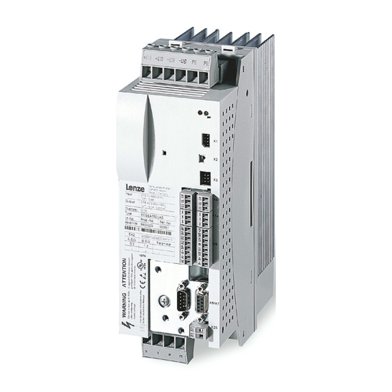
- Page 3 Show/Hide Bookmarks +UG +UG -UG -UG PE PE ECSXK001 Capacitor module ECSxK Accessory kit with fixing material Safety instructions for modules of the ECS series Connections: - DC-bus supply - PE Control connection for bridging the charging current limitation ...
- Page 4 Show/Hide Bookmarks EDBCSXKXXX EN 1.0...
-
Page 5: Table Of Contents
............General safety and application information for Lenze capacitor modules . - Page 6 Show/Hide Bookmarks Contents Commissioning ............Appendix .
-
Page 7: Preface And General Information
Drive systems with: ECSxAxxx axis modules ECSxExxx power supply modules ECSxKxxx capacitor modules Other Lenze drive components 24 V supply 24 V DC supply Low-voltage supply of the control card in a voltage range of 20 ... 30 V DC (±0 V) of ”Safe standstill”... -
Page 8: Legal Regulations
The specifications, processes, and circuitry described in these Instructions are for guidance only and must be adapted to your own specific application. Lenze does not take responsibility for the suitability of the process and circuit proposals. -
Page 9: Safety Instructions
(according to Low-Voltage Directive 73/23/EWG) General During operation, Lenze capacitor modules can include live parts, depending on their type of protection. Surfaces can be hot. If the required cover is removed or the modules are used inappropriately or installed or operated incorrectly, severe damage to persons or material can occur. - Page 10 Show/Hide Bookmarks Safety instructions General safety and application information for Lenze capacitor modules Installation The capacitor modules must be installed and cooled according to the regulations given in the corresponding Instructions. Ensure careful handling and avoid mechanical stress. Do not bend any components and do not change the insulation distances during transport and handling.
- Page 11 Show/Hide Bookmarks Safety instructions General safety and application information for Lenze capacitor modules Disposal Recycle metals and plastics. Dispose of printed circuit board assemblies according to the state of the art. The product-specific safety and application notes in these Instructions must also be observed! ...
-
Page 12: Residual Hazards
Show/Hide Bookmarks Safety instructions Residual hazards Residual hazards Protection of persons ƒ Before working on the capacitor module, check that no voltage is applied to the power terminals, – because the power terminals +UG and -UG at the supply module remain live for at least 3 minutes after mains switch-off. -
Page 13: Safety Instructions For The Installation According To Ul Or Ur
Show/Hide Bookmarks Safety instructions Safety instructions for the installation according to UL or UR Safety instructions for the installation according to U or U Warnings! General markings: Use 60/75 °C or 75 °C copper wire only. ƒ Maximum ambient temperature 55 °C, with reduced output current. ƒ... -
Page 14: Definition Of Notes Used
Show/Hide Bookmarks Safety instructions Definition of notes used Definition of notes used The following signal words and symbols are used in this documentation to indicate dangers and important information: Safety instructions Structure of safety instructions: Danger! (characterises the type and severity of danger) Note (describes the danger and gives information about how to prevent dangerous situations) -
Page 15: Technical Data
Show/Hide Bookmarks Technical data General data/operating conditions Technical data General data/operating conditions Standards and operating conditions Conformity Low-Voltage Directive (73/23/EWG) Approvals UL 508C Power Conversion Equipment Underwriter Laboratories (File No. E132659) for USA and Canada Vibration resistance Accelerational stability up to 0.7 g (Germanischer Lloyd, general conditions) Climatic conditions Class 3K3 to EN 50178 (without condensation, relative humidity 30 ... -
Page 16: Rated Data
Show/Hide Bookmarks Technical data Rated data Rated data Rated data Type ECSxK001xxx ECSxK002xxx Data for operation with upstream supply module on mains mains voltage DC-bus voltage 0 ... 770 Rated AC current 17,5 Rated power [kW] Rated power with mains choke [kW] Capacity C [µF]... -
Page 17: Mechanical Installation
Show/Hide Bookmarks Mechanical installation Important notes Mechanical installation Important notes ƒ ECSxKxxx capacitor modules are provided with IP20 protection and can therefore only be used for installation into control cabinets. – For thermally separated mounting (ECSDKxxx): IP54 on the heatsink side ƒ... -
Page 18: Mounting With Fixing Rails (Standard)
Show/Hide Bookmarks Mechanical installation Mounting with fixing rails (standard) Mounting with fixing rails (standard) Type ECSEKxxx For standard mounting into the control cabinet the capacitor module types ECSEKxxx must be used. The accessories required for mounting are included in the scope of supply. Dimensions ECSXK005 Fig.4-1... -
Page 19: Thermally Separated Mounting ("Push-Through Technique")
Show/Hide Bookmarks Mechanical installation Thermally separated mounting (”push-through technique”) Thermally separated mounting (”push-through technique”) Type ECSDKxxx For thermally separated mounting the capacitor modules of ECSDKxxx type must be used. The accessories required for mounting are included in the scope of supply. ƒ... - Page 20 Show/Hide Bookmarks Mechanical installation Thermally separated mounting (”push-through technique”) Dimensions of mounting cutout ECSXK063 Fig.4-3 Dimensions of mounting cutout for thermally separated mounting, ECSDKxxx type Mounting plate Mounting cutout for ECSDK001 Mounting cutout for ECSDK002 Capacitor modules Dimensions [mm] Type Size...
-
Page 21: Mounting In "Cold Plate" Technique
Show/Hide Bookmarks Mechanical installation Mounting in ”cold plate” technique Mounting in ”cold plate” technique Type ECSCKxxx It is possible to mount the capacitor modules in cold-plate technique, for instance, onto collective coolers. For this mounting, the capacitor modules type ECSCAxxx must be used. Dimensions ECSXK009 Fig.4-4... - Page 22 Show/Hide Bookmarks Mechanical installation Mounting in ”cold plate” technique Mounting À Á Â ECSXK030 Fig.4-5 Mounting in ”cold plate” technique For mounting the capacitor module ECSCKxxx proceed as follows: 1. Prepare the fixing holes (see drawing) 2. Clean and degrease the contact area of cooler and heatsink (e. g. with methylated spirit).
-
Page 23: Electrical Installation
Show/Hide Bookmarks Electrical installation Important notes Protection of persons Electrical installation Important notes Stop! The capacitor module contains electrostatically sensitive components. Prior to assembly and service operations, the personnel must be free of electrostatic charge. 5.1.1 Protection of persons ... -
Page 24: Device Protection
Show/Hide Bookmarks Electrical installation Important notes Device protection 5.1.2 Device protection Stop! All pluggable connection terminals must only be connected or disconnected ƒ when no voltage is applied. The power terminals +UG, -UG and PE are not protected against polarity ƒ... -
Page 25: Drive System On The Mains
Show/Hide Bookmarks Electrical installation Drive system on the mains Supply form/electrical supply conditions Drive system on the mains These information apply to the drive system, consisting of: ƒ ECSxExxx power supply module ƒ ECSxKxxx capacitor module ƒ ECSxAxxx axis module ƒ... -
Page 26: Installation Of A Dc-Typical Drive System
Show/Hide Bookmarks Electrical installation Installation of a DC-typical drive system Installation of a DC-typical drive system General notes ƒ The electromagnetic compatibility of a machine depends on the type of installation and care taken.Especially consider the following: – Structure – Filtering –... - Page 27 Show/Hide Bookmarks Electrical installation Installation of a DC-typical drive system Filtering ƒ Use RFI filters and mains chokes which are assigned to the power supply modules: – RFI filters reduce impermissible high-frequency interferences to a permissible value. – Mains chokes reduce low-frequency interferences which depend on the motor cable and its length.
-
Page 28: Power Connections
When using capacitor modules in the DC-bus connection with basic devices of the 82xx and 93xx series, use the following fuses: Fuse Support Value [A] Lenze type Lenze type EFSGR0500ANIN EFH20007 Warnings! Use UL-approved cables, fuses and fuse holders only. - Page 29 Show/Hide Bookmarks Electrical installation Power connections Specification of the cables used Cable cross-sections Terminal Function Screw tightening torques Possible cable cross-sections rigid – 0.2 ... 10 mm – AWG 24 ... 8 flexible – 0.2 ... 10 mm – AWG 24 ... 10 1.2 ...
-
Page 30: Control Connection
Show/Hide Bookmarks Electrical installation Control connection Control connection Terminal Function Electrical data Connection for bridging the charging current 21.8 ... 30 V DC, limitation max. 1.5 A The polarity does not influence the function of the charging current limitation. EDBCSXKXXX EN 1.0... -
Page 31: Wiring
Show/Hide Bookmarks Electrical installation Wiring Operation with ECSxE power supply module Wiring 5.6.1 Operation with ECSxE power supply module Install the capacitor module ECSxKxxx between the power supply module and the axis module(s). If the total cable length in the DC-bus connection is longer than 5 m, install the capacitor module as close as possible to the axis module with the highest power. - Page 32 Show/Hide Bookmarks Electrical installation Wiring Operation with ECSxE power supply module HIGH (1) ECSxA: X6/SI1 (CINH) ECSxE: X6/DO1 LOW (0) t [s] 100 % t [s] HIGH (1) ECSxK: X26 (24 V DC) ECSxE: X6/DI1 ECSxE: X6/DI2 LOW (0) t [s] HIGH (1) LOW (0) t [s]...
-
Page 33: Operation With Another Supplier
Show/Hide Bookmarks Electrical installation Wiring Operation with another supplier 5.6.2 Operation with another supplier Stop! After mains connection, wait at least one second before bridging the ƒ charging current limitation (X26 = HIGH). Only release the controller (X6/SI1 = HIGH) if the charging current limitation ƒ... -
Page 34: Commissioning
Show/Hide Bookmarks Commissioning Commissioning Before you start Prior to initial switch-on of the drive system, check the wiring of the capacitor module for completeness, short-circuit, and earth fault: ƒ Power connection (X23): – Polarity of the DC-bus voltage supply via terminals +UG and -UG ƒ... -
Page 35: Appendix
The DC bus must only be fused when using the capacitor module with basic device of 82xx and 93xx series. Here, the following fuses must be used: Fuse Support Value [A] Lenze type Lenze type EFSGR0500ANIN EFH20007 EDBCSXKXXX EN 1.0... -
Page 36: Index
Show/Hide Bookmarks Appendix Index Index DC bus voltage, connection, 28 DC-bus fuses, 35 Accessories, 35 - connectors, 35 Definition of notes used, 14 - DC bus fuses, 35 Definitions, 7 Appendix, 35 Degree of pollution, 15 Application as directed, 8 Device protection, 12 Approvals, 15 Dimensions, 16... - Page 37 Show/Hide Bookmarks Appendix Index Free space, 15 Fuses, 28 , 35 Manufacturer, 8 Mechanical installation, 17 - important notes, 17 General electrical data, 15 - mounting in ”cold plate” technique, type ECSCKxxx, 21 - mounting with fixing rails, type ECSEKxxx, 18 - thermally separated mounting, type ECSDKxxx, 19 Mounting in ”cold plate”...
- Page 38 - operating conditions, 15 - design, 14 - rated data, 16 - device protection, 12 - standards, 15 - general, for Lenze capacitor modules, 9 Temperature range, 15 - protection of persons, 12 Terminal assignment Shielded cables, 28 - control connection (X26), 30...
- Page 39 Show/Hide Bookmarks Appendix EDBCSXKXXX EN 1.0...
- Page 40 Show/Hide Bookmarks Lenze Drive Systems GmbH EDBCSXKXXX 1.0 09/2004 TD14 2004 Hans-Lenze-Straße 1 31855 Aerzen Germany +49 (0) 51 54 82-0 Service 00 80 00 24 4 68 77 (24 h helpline) Service +49 (0) 51 54 82-1112 E-Mail Lenze@Lenze.de...
Need help?
Do you have a question about the ECSxK001 series and is the answer not in the manual?
Questions and answers