Sign In
Upload
Manuals
Brands
Lenze Manuals
Servo Drives
ECS series
Lenze ECS series Servo Drive Manuals
Manuals and User Guides for Lenze ECS series Servo Drive. We have
10
Lenze ECS series Servo Drive manuals available for free PDF download: Operating Instructions Manual, Mounting Instructions
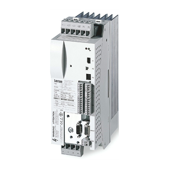
Lenze ECS series Operating Instructions Manual (485 pages)
Axis module - Application
Brand:
Lenze
| Category:
Control Unit
| Size: 25 MB
Table of Contents
Scope of Supply
5
Status Displays
5
Table of Contents
6
Preface and General Information
15
About These Operating Instructions
15
Conventions Used in this Manual
15
Terminology Used
16
Code Descriptions
17
Structure of the System Block Descriptions
18
Features of the Ecsxa Axis Module
19
Scope of Supply
20
Legal Regulations
21
System Block Introduction
22
System Blocks ˘ Principle
22
Node Numbers
23
Access Via System Variables
24
Access Via Absolute Addresses
25
Definition of the Inputs/Outputs
25
Integrate System Blocks into DDS
27
Signal Types and Scaling
28
Safety Instructions
29
General Safety and Application Notes for Lenze Controllers
29
Thermal Motor Monitoring
33
Forced Ventilated or Naturally Ventilated Motors
34
Self−Ventilated Motors
35
Residual Hazards
37
Motor Protection
38
Safety Instructions for the Installation According to UL
39
Notes Used
40
Application Notes
40
Technical Data
41
General Data and Operating Conditions
41
Rated Data
43
Current Characteristics
45
Increased Continuous Current Depending on the Control Factor
45
Device Protection by Current Derating
48
Mechanical Installation
49
Important Notes
49
Mounting with Fixing Rails (Standard Installation)
50
Dimensions
50
Mounting Steps
51
Mounting with Thermal Separation (Push−Through Technique)
52
Dimensions
53
Mounting Steps
55
Mounting in Cold−Plate Design
56
Ambient Conditions
56
Dimensions
57
Mounting Steps
58
Electrical Installation
59
Installation According to EMC (Installation of a Ce−Typical Drive System)
59
General Information
59
Power Terminals
62
Connection to the DC Bus (+UG, −UG)
65
Connection Plan for Mimimum Wiring with Internal Brake Resistor
67
Connection Plan for Mimimum Wiring with External Brake Resistor
69
Motor Connection
71
Motor Holding Brake Connection
72
Connection of an Ecsxk
74
Control Terminals
75
Cable Cross−Sections and Screw−Tightening Torques
78
Digital Inputs and Outputs
79
Analog Input
80
Safe Torque off
81
During Operation
83
Automation Interface (AIF)
90
Wiring of System Bus (CAN)
91
Wiring of the Feedback System
96
Resolver Connection
97
Encoder Connection
98
Digital Frequency Input/Output (Encoder Simulation)
101
Commissioning
103
Before You Start
103
Commissioning Steps (Overview)
104
Carrying out Basic Settings with GDC
105
Loading the Lenze Setting
107
Setting of Mains Data
108
Selecting the Function of the Charging Current Limitation
108
Setting the Voltage Thresholds
109
Entry of Motor Data for Lenze Motors
110
Holding Brake Configuration
112
Setting of the Feedback System for Position and Speed Control
113
Resolver as Position and Speed Encoder
114
Ttl/Sincos Encoder as Position and Speed Encoder
116
Ttl/Sincos Encoder as Position Encoder and Resolver as Speed Encoder
119
Absolute Value Encoder as Position and Speed Encoder
123
Absolute Value Encoder as Position Encoder and Resolver as Speed Encoder
126
Setting the Polarity of Digital Inputs and Outputs
130
Entry of Machine Parameters
131
Controller Enable (CINH = 0)
132
Operation with Motors from Other Manufacturers
133
Entering Motor Data Manually
133
Checking the Direction of Rotation of the Motor Feedback System
136
Adjusting Current Controller
137
Effecting Rotor Position Adjustment
139
Optimising the Drive Behaviour after Start
142
Speed Controller Adjustment
142
Adjustment of Field Controller and Field Weakening Controller
145
Resolver Adjustment
148
Parameter Setting
149
General Information
149
Parameter Setting with "Global Drive Control" (GDC)
150
Parameter Setting with the XT EMZ9371BC Keypad
151
Connecting the Keypad
151
Description of the Display Elements
152
Description of the Function Keys
154
Changing and Saving Parameters
155
System Bus (CAN / CAN−AUX) Configuration
156
Setting the CAN Node Address and Baud Rate
156
Settings Via DIP Switch
157
Node Address Setting
157
Settings Via Codes
159
Individual Addressing
161
Determining the Boot−Up Master for the Drive System
163
Setting the Boot−Up Time/Cycle Time
164
Reset Node
166
Axis Synchronisation (CAN Synchronisation)
167
Monitoring of the Synchronisation (Sync Time Slot)
170
Axis Synchronisation Via CAN
171
Axis Synchronisation Via Terminal X6/DI1
172
Node Guarding
173
CAN Management
175
Mapping Indices to Codes
176
Functional Principle
177
Diagnostics Codes
178
CAN Bus Status (C0359/C2459)
178
CAN Telegram Counter (C0360/2460)
179
CAN Bus Load (C0361/2461)
180
Remote Parameterisation (Gateway Function)
181
Configuring the AIF Interface (X1)
183
CAN Baud Rate
183
CAN Boot up (AIF)
184
Node Address (Node ID)
185
Identifiers of the Process Data Objects
186
Individual Identifier Assignment
187
Display of the Identifier Set
188
Cycle Time (XCAN1_OUT
189
Synchronisation
191
XCAN Sync Response
191
XCAN Sync Identifier
191
XCAN Sync Tx Transmission Cycle
192
Reset Node
192
Monitoring
193
Time Monitoring for XCAN1_IN
193
Bus off
194
Operating Status of AIF Interface
196
Monitoring Functions
197
Fault Responses
198
Overview of Monitoring Functions
199
Configuring Monitoring Functions
203
Monitoring Times for Process Data Input Objects
203
Time−Out Monitoring for Activated Remote Parameterisation
205
Short Circuit Monitoring (OC1)
206
Earth Fault Monitoring (OC2)
206
Motor Temperature Monitoring (OH3, OH7)
207
Heatsink Temperature Monitoring (OH, OH4)
209
Monitoring of Internal Device Temperature (OH1, OH5)
210
Function Monitoring of Thermal Sensors (H10, H11)
211
Current Load of Controller (I X T Monitoring: OC5, OC7)
212
Current Load of Motor (I2 X T Monitoring: OC6, OC8)
215
DC−Bus Voltage Monitoring (OU, LU)
219
Voltage Supply Monitoring − Control Electronics (U15)
222
Motor Phase Failure Monitoring (LP1)
222
Advertisement
Lenze ECS series Operating Instructions Manual (483 pages)
Axis module ? Application
Brand:
Lenze
| Category:
Control Unit
| Size: 3 MB
Table of Contents
Table of Contents
5
1 Preface and General Information
14
About These Operating Instructions
14
Conventions Used in this Manual
14
Terminology Used
15
Code Descriptions
16
Structure of the System Block Descriptions
17
Features of the Ecsxa Axis Module
18
Scope of Supply
19
Legal Regulations
20
System Block Introduction
21
System Blocks ˘ Principle
21
Node Numbers
22
Access Via System Variables
23
Access Via Absolute Addresses
24
Definition of the Inputs/Outputs
24
Integrate System Blocks into DDS
26
Signal Types and Scaling
27
2 Safety Instructions
28
General Safety and Application Notes for Lenze Controllers
28
Thermal Motor Monitoring
32
Forced Ventilated or Naturally Ventilated Motors
33
Self−Ventilated Motors
34
Residual Hazards
36
Safety Instructions for the Installation According to UL
38
Notes Used
39
3 Technical Data
40
General Data and Operating Conditions
40
Rated Data
42
Current Characteristics
44
Increased Continuous Current Depending on the Control Factor
44
Device Protection by Current Derating
47
4 Mechanical Installation
48
Important Notes
48
Mounting with Fixing Rails (Standard Installation)
49
Dimensions
49
Mounting Steps
50
Mounting with Thermal Separation (Push−Through Technique)
51
Dimensions
52
Mounting Steps
54
Mounting in Cold−Plate Design
55
Dimensions
56
Mounting Steps
57
5 Electrical Installation
58
Installation According to EMC (Installation of a Ce−Typical Drive System)
58
Power Terminals
61
Connection to the DC Bus (+UG, −UG)
64
Connection Plan for Mimimum Wiring with Internal Brake Resistor
66
Connection Plan for Mimimum Wiring with External Brake Resistor
68
Motor Connection
70
Motor Holding Brake Connection
71
Connection of an Ecsxk
73
Control Terminals
74
Digital Inputs and Outputs
78
Analog Input
79
Safe Torque off
80
Automation Interface (AIF)
89
Wiring of System Bus (CAN)
90
Wiring of the Feedback System
95
Resolver Connection
96
Encoder Connection
97
Digital Frequency Input/Output (Encoder Simulation)
100
6 Commissioning
102
Before You Start
102
Commissioning Steps (Overview)
103
Carrying out Basic Settings with GDC
104
Loading the Lenze Setting
106
Setting of Mains Data
107
Selecting the Function of the Charging Current Limitation
107
Setting the Voltage Thresholds
108
Entry of Motor Data for Lenze Motors
109
Holding Brake Configuration
111
Setting of the Feedback System for Position and Speed Control
112
Resolver as Position and Speed Encoder
113
Ttl/Sincos Encoder as Position and Speed Encoder
115
Ttl/Sincos Encoder as Position Encoder and Resolver as Speed Encoder
118
Absolute Value Encoder as Position and Speed Encoder
122
Absolute Value Encoder as Position Encoder and Resolver as Speed Encoder
125
Setting the Polarity of Digital Inputs and Outputs
129
Entry of Machine Parameters
130
Controller Enable (CINH = 0)
131
Operation with Motors from Other Manufacturers
132
Entering Motor Data Manually
132
Checking the Direction of Rotation of the Motor Feedback System
135
Adjusting Current Controller
136
Effecting Rotor Position Adjustment
138
Optimising the Drive Behaviour after Start
141
Speed Controller Adjustment
141
Adjustment of Field Controller and Field Weakening Controller
144
Resolver Adjustment
147
7 Parameter Setting
148
General Information
148
Parameter Setting with "Global Drive Control" (GDC)
149
Parameter Setting with the XT EMZ9371BC Keypad
150
Connecting the Keypad
150
Description of the Display Elements
151
Description of the Function Keys
153
Changing and Saving Parameters
154
8 System Bus (CAN / CAN−AUX) Configuration
155
Setting the CAN Node Address and Baud Rate
155
Settings Via DIP Switch
156
Settings Via Codes
158
Individual Addressing
160
Determining the Boot−Up Master for the Drive System
162
Setting the Boot−Up Time/Cycle Time
163
Reset Node
165
Axis Synchronisation (CAN Synchronisation)
166
Monitoring of the Synchronisation (Sync Time Slot)
169
Axis Synchronisation Via CAN
170
Axis Synchronisation Via Terminal X6/DI1
171
Node Guarding
172
CAN Management
174
Mapping Indices to Codes
175
Diagnostics Codes
177
CAN Bus Status (C0359/C2459)
177
CAN Telegram Counter (C0360/2460)
178
CAN Bus Load (C0361/2461)
179
Remote Parameterisation (Gateway Function)
180
9 Configuring the AIF Interface (X1)
182
CAN Baud Rate
182
CAN Boot up (AIF)
183
Node Address (Node ID)
184
Identifiers of the Process Data Objects
185
Individual Identifier Assignment
186
Display of the Identifier Set
187
Cycle Time (XCAN1_OUT
188
Synchronisation
190
XCAN Sync Response
190
XCAN Sync Identifier
190
XCAN Sync Tx Transmission Cycle
191
Reset Node
191
Monitoring
192
Time Monitoring for XCAN1_IN
192
Bus off
193
Operating Status of AIF Interface
195
10 Monitoring Functions
196
Fault Responses
197
Overview of Monitoring Functions
198
Configuring Monitoring Functions
202
Monitoring Times for Process Data Input Objects
202
Time−Out Monitoring for Activated Remote Parameterisation
204
Short Circuit Monitoring (OC1)
205
Earth Fault Monitoring (OC2)
205
Motor Temperature Monitoring (OH3, OH7)
206
Heatsink Temperature Monitoring (OH, OH4)
208
Monitoring of Internal Device Temperature (OH1, OH5)
209
Function Monitoring of Thermal Sensors (H10, H11)
210
Current Load of Controller (I X T Monitoring: OC5, OC7)
211
Current Load of Motor (I2 X T Monitoring: OC6, OC8)
214
DC−Bus Voltage Monitoring (OU, LU)
218
Voltage Supply Monitoring − Control Electronics (U15)
221
Motor Phase Failure Monitoring (LP1)
221
Monitoring of the Resolver Cable (Sd2)
222
Motor Temperature Sensor Monitoring (Sd6)
223
Monitoring of the Absolute Value Encoder Initialisation (Sd7)
224
Sin/Cos Signal Monitoring (Sd8)
225
Monitoring of the Speed System Deviation (Nerr)
226
Monitoring of Max. System Speed (NMAX)
227
Monitoring of the Rotor Position Adjustment (PL)
228
Lenze ECS series Operating Instructions Manual (484 pages)
Axis module Speed & Torque
Brand:
Lenze
| Category:
Control Unit
| Size: 3 MB
Table of Contents
Table of Contents
5
1 Preface and General Information
12
About These Operating Instructions
12
Terminology Used
13
Code Descriptions
14
Signal Types and Scaling
15
Features of the Ecsxs Axis Module
16
Scope of Supply
17
Legal Regulations
18
2 Safety Instructions
19
General Safety and Application Notes for Lenze Controllers
19
Thermal Motor Monitoring
23
Forced Ventilated or Naturally Ventilated Motors
24
Self−Ventilated Motors
25
Residual Hazards
27
Safety Instructions for the Installation According to UL
29
Notes Used
30
3 Technical Data
31
General Data and Operating Conditions
31
Rated Data
33
Current Characteristics
35
Increased Continuous Current Depending on the Control Factor
35
Device Protection by Current Derating
38
4 Mechanical Installation
39
Important Notes
39
Mounting with Fixing Rails (Standard Installation)
40
Dimensions
40
Mounting Steps
41
Mounting with Thermal Separation (Push−Through Technique)
42
Dimensions
43
Mounting Steps
45
Mounting in Cold−Plate Design
46
Dimensions
47
Mounting Steps
48
5 Electrical Installation
49
Installation According to EMC (Installation of a Ce−Typical Drive System)
49
Power Terminals
52
Connection to the DC Bus (+UG, −UG)
55
Connection Plan for Mimimum Wiring with Internal Brake Resistor
57
Connection Plan for Mimimum Wiring with External Brake Resistor
59
Motor Connection
61
Motor Holding Brake Connection
62
Connection of an Ecsxk
64
Control Terminals
65
Digital Inputs and Outputs
69
Analog Input
70
Safe Torque off
71
Automation Interface (AIF)
80
Wiring of System Bus (CAN)
81
Wiring of the Feedback System
86
Resolver Connection
87
Encoder Connection
88
Digital Frequency Input/Output (Encoder Simulation)
91
6 Commissioning
93
Before You Start
93
Commissioning Steps (Overview)
94
Carrying out Basic Settings with GDC
95
Loading the Lenze Setting
97
Setting of Mains Data
98
Selecting the Function of the Charging Current Limitation
98
Setting the Voltage Thresholds
99
Entry of Motor Data for Lenze Motors
100
Holding Brake Configuration
102
Setting of the Feedback System for Position and Speed Control
103
Resolver as Position and Speed Encoder
104
Ttl/Sincos Encoder as Position and Speed Encoder
106
Ttl/Sincos Encoder as Position Encoder and Resolver as Speed Encoder
109
Absolute Value Encoder as Position and Speed Encoder
113
Absolute Value Encoder as Position Encoder and Resolver as Speed Encoder
117
Configuring the Digital Inputs and Outputs
121
Selecting the Operating Mode/Control Structure
126
Entry of Machine Parameters
141
Setpoint Selection
142
Controller Enable (CINH = 0)
143
Quick Stop (QSP)
144
Operation with Motors from Other Manufacturers
145
Optimising the Drive Behaviour after Start
154
7 Parameter Setting
161
General Information
161
Parameter Setting with "Global Drive Control" (GDC)
162
Parameter Setting with the XT EMZ9371BC Keypad
163
Connecting the Keypad
163
Description of the Display Elements
164
Description of the Function Keys
166
Changing and Saving Parameters
167
8 Configuration
168
Configuring Motionbus/System Bus (CAN)
169
Setting CAN Node Address and Baud Rate
169
Individual Addressing
173
Defining Boot−Up Master in the Drive System
175
Setting of Boot−Up Time/Cycle Time
176
Executing a Reset Node
178
Axis Synchronisation (CAN Synchronisation)
179
Monitoring of the Synchronisation (Sync Time Slot)
181
Axis Synchronisation Via CAN
182
Axis Synchronisation Via Terminal X6/DI1
183
Node Guarding
184
CAN Management
186
Diagnostics Codes
187
CAN Bus Status (C0359)
187
CAN Telegram Counter (C0360)
188
CAN Bus Load (C0361)
189
Remote Parameterisation (Gateway Function)
190
9 Monitoring Functions
192
Fault Responses
193
Overview of Monitoring Functions
194
Configuring Monitoring Functions
198
Monitoring Times for Process Data Input Objects
198
Time−Out Monitoring for Activated Remote Parameterisation
200
Short Circuit Monitoring (OC1)
201
Earth Fault Monitoring (OC2)
201
Motor Temperature Monitoring (OH3, OH7)
202
Heatsink Temperature Monitoring (OH, OH4)
204
Monitoring of Internal Device Temperature (OH1, OH5)
205
Function Monitoring of Thermal Sensors (H10, H11)
206
Current Load of Controller (I X T Monitoring: OC5, OC7)
207
Current Load of Motor (I2 X T Monitoring: OC6, OC8)
210
DC−Bus Voltage Monitoring (OU, LU)
214
Voltage Supply Monitoring − Control Electronics (U15)
217
Motor Phase Failure Monitoring (LP1)
217
Monitoring of the Resolver Cable (Sd2)
218
Motor Temperature Sensor Monitoring (Sd6)
219
Monitoring of the Absolute Value Encoder Initialisation (Sd7)
220
Sin/Cos Signal Monitoring (Sd8)
221
Monitoring of the Speed System Deviation (Nerr)
222
Monitoring of Max. System Speed (NMAX)
223
Monitoring of the Rotor Position Adjustment (PL)
224
Advertisement
Lenze ECS series Operating Instructions Manual (375 pages)
Axis module - Motion
Brand:
Lenze
| Category:
Control Unit
| Size: 3 MB
Table of Contents
Table of Contents
5
1 Preface and General Information
11
About These Operating Instructions
11
Terminology Used
12
Code Descriptions
13
Features of the Axis Module Ecsxm (Motion)
14
Structure
15
Scope of Supply
16
Legal Regulations
17
2 Safety Instructions
18
General Safety and Application Notes for Lenze Controllers
18
Thermal Motor Monitoring
22
Forced Ventilated or Naturally Ventilated Motors
23
Self−Ventilated Motors
24
Residual Hazards
26
Safety Instructions for the Installation According to UL
28
Notes Used
29
3 Technical Data
30
General Data and Operating Conditions
30
Rated Data
32
Current Characteristics
34
Increased Continuous Current Depending on the Control Factor
34
Device Protection by Current Derating
37
4 Mechanical Installation
38
Important Notes
38
Mounting with Fixing Rails (Standard Installation)
39
Dimensions
39
Mounting Steps
40
Mounting with Thermal Separation (Push−Through Technique)
41
Dimensions
42
Mounting Steps
44
Mounting in Cold−Plate Design
45
Dimensions
46
Mounting Steps
47
5 Electrical Installation
48
Installation According to EMC (Installation of a Ce−Typical Drive System)
48
Power Terminals
51
Connection to the DC Bus (+UG, −UG)
54
Connection Plan for Mimimum Wiring with Internal Brake Resistor
56
Connection Plan for Mimimum Wiring with External Brake Resistor
58
Motor Connection
60
Motor Holding Brake Connection
61
Connection of an Ecsxk
63
Control Terminals
64
Digital Inputs and Outputs
68
Analog Input
69
Safe Torque off
70
Automation Interface (AIF)
79
Wiring of System Bus (CAN)
80
Wiring of the Feedback System
85
Resolver Connection
86
Encoder Connection
87
Digital Frequency Input/Output (Encoder Simulation)
90
6 Commissioning
92
Before You Start
92
Commissioning Steps (Overview)
93
Basic Settings with GDC
94
Setting of Homing
96
Loading the Lenze Setting
100
Setting of Mains Data
101
Selecting the Function of the Charging Current Limitation
101
Setting the Voltage Thresholds
102
Entry of Motor Data for Lenze Motors
103
Holding Brake Configuration
105
Closing the Brake
107
Opening the Brake
108
Setting of the Feedback System for Position and Speed Control
109
Resolver as Position and Speed Encoder
110
Resolver as Absolute Value Encoder
112
Ttl/Sincos Encoder as Position and Speed Encoder
113
Ttl/Sincos Encoder as Position Encoder and Resolver as Speed Encoder
117
Absolute Value Encoder as Position and Speed Encoder
121
Absolute Value Encoder as Position Encoder and Resolver as Speed Encoder
126
Selecting the Control Interface (C4010)
130
Process Data to the Axis Module (Control Word Ctrl1 and Setpoints)
131
Process Data from the Axis Module (Status Words and Actual Values)
134
Toggle−Bit Monitoring
136
Entry of Machine Parameters
138
Configuring the Digital Inputs and Outputs
140
Digital Inputs for Communication Via the Motionbus (CAN) X4
141
Digital Inputs for Communication Via the Automation Interface (AIF) X1
141
Setting the Polarity of Digital Inputs and Outputs
142
Setting of Homing Parameters
143
Homing Parameters
143
Homing Modes
145
Shifting the Zero Position with Regard to the Home Position (Offsets C3011, C3012)
155
Example: Reference Search with Linear Positioning Axis
156
Example: Reference Search with Continuous Positioning Axis
158
Selection of the Operating Mode
160
Operating Mode "Interpolated Position Mode" (Ip−Mode)
161
Homing" Operating Mode
164
Manual Jog" Operating Mode
165
Velocity" Operating Mode
167
Controller Enable (CINH = 0)
169
Following Error Monitoring (C3030, C3031)
170
Evaluating and Retracting from Hardware Limit Switch
172
Evaluating Hardware Limit Switches
172
Retracting from Hardware Limit Switches
172
Quick Stop (QSP)
173
Operation with Motors from Other Manufacturers
174
Entering Motor Data Manually
174
Checking the Direction of Rotation of the Motor Feedback System
177
Adjusting Current Controller
178
Effecting Rotor Position Adjustment
180
Optimising the Drive Behaviour after Start
183
Speed Controller Adjustment
183
Adjustment of Field Controller and Field Weakening Controller
185
Resolver Adjustment
188
Lenze ECS series Operating Instructions Manual (306 pages)
Axis module ˘ "Motion" application
Brand:
Lenze
| Category:
Control Unit
| Size: 2 MB
Table of Contents
Table of Contents
5
1 Preface and General Information
10
How to Use These Operating Instructions
10
Terminology Used
10
Code Descriptions
11
Features of the Axis Module Ecsxm
12
Structure
13
Scope of Supply
14
Legal Regulations
15
2 Safety Instructions
16
General Safety and Application Notes for Lenze Controllers
16
Residual Hazards
19
Safety Instructions for the Installation According to UL or UR
21
Definition of Notes Used
22
3 Technical Data
23
General Data and Operating Conditions
23
Rated Data
25
Current Characteristics
27
Increased Continuous Current Depending on the Control Factor
27
Device Protection by Current Derating
30
4 Mechanical Installation
31
Important Notes
31
Mounting with Fixing Rails (Standard Installation)
32
Dimensions
32
Assembly Steps
33
Mounting with Thermal Separation (Push−Through Technique)
34
Dimensions
35
Assembly Steps
37
Mounting in Cold−Plate Design
38
Dimensions
39
Assembly Steps
40
5 Electrical Installation
41
Installation According to EMC (Installation of a Ce−Typical Drive System)
41
Power Terminals
44
Connection to the DC Bus (+UG, −UG)
47
Connection Plans
49
Motor Connection
51
Motor Holding Brake Connection
52
Connection at Capacitor Module Ecsxk
54
Control Terminals
55
Digital Inputs and Outputs
58
Analog Input
59
Safe Torque off
60
Automation Interface (AIF)
69
Wiring of Motionbus/System Bus (CAN)
70
Wiring of the Feedback System
74
Resolver Connection
74
Encoder Connection
75
6 Commissioning
79
Before You Start
79
Commissioning Steps (Overview)
80
Basic Settings with GDC
81
Setting of Homing
83
Loading the Lenze Setting
86
Setting of Mains Data
87
Selecting the Function of the Charging Current Limitation
87
Setting the Voltage Thresholds
88
Entry of Motor Data for Lenze Motors
89
Holding Brake Configuration
91
Closing the Brake
92
Opening the Brake
93
Setting of the Feedback System for Position and Speed Control
94
Resolver for Position and Speed Control
94
Codes for Setting the Resolver Feedback
94
Resolver as Absolute Value Encoder
96
Incremental Encoder / Sin/Cos Encoder Without Serial Communication
97
Absolute Value Encoder (Hiperface®, Single−Turn/Multi−Turn)
98
Codes for Setting the Encoder Feedback
100
Configuration of Control Interface (Control and Status Word)
103
Process Data to the Axis Module
104
Process Data from the Axis Module
106
Toggle−Bit Monitoring
108
Entry of Machine Parameters
110
Setting of Homing Parameters
112
Homing Parameters
112
Homing Modes
114
Shifting of the Zero Position (Offset Selection)
124
Example: Reference Search with Linear Positioning Axis
125
Example: Reference Search with Continuous Positioning Axis
127
Selection of the Operating Mode
129
Velocity" Operating Mode
130
Homing" Operating Mode
132
Operating Mode "Interpolated Position Mode" (Ip−Mode)
134
Manual Jog" Operating Mode
137
Controller Enable
139
Following Error Monitoring
140
Evaluation of Hardware Limit Switches
142
Quick Stop (QSP)
143
Operation with Servo Motors from Other Manufacturers
144
Entering Motor Data Manually
144
Checking the Direction of Rotation of the Resolver
146
Adjusting Current Controller
147
Effecting Rotor Position Adjustment
149
Optimising the Drive Behaviour after Start
152
Speed Controller Adjustment
152
Adjustment of Field Controller and Field Weakening Controller
154
Resolver Adjustment
157
Lenze ECS series Mounting Instructions (200 pages)
Panel-mounted axis module
Brand:
Lenze
| Category:
Control Unit
| Size: 1 MB
Table of Contents
Deutsch
6
Table of Contents
6
1 Über diese Dokumentation
7
2 Sicherheitshinweise
8
Allgemeine Sicherheits− und Anwendungshinweise für Lenze−Antriebsregler
8
Motor Thermisch Überwachen
12
Fremdbelüftete oder Selbstgekühlte Motoren
14
Eigenbelüftete Motoren
16
Restgefahren
19
Sicherheitshinweise für die Installation nach UL
21
3 Technische Daten
22
Allgemeine Daten und Einsatzbedingungen
22
Bemessungsdaten
24
4 Mechanische Installation
26
Wichtige Hinweise
26
Montage mit Befestigungsschienen (Standard−Einbau)
27
Abmessungen
27
Montageschritte
28
5 Elektrische Installation
29
Emv−Gerechte Installation (Aufbau des Ce−Typischen Antriebssystems)
29
Leistungsanschlüsse
32
Anschluss an den DC−Zwischenkreis (+UG, −UG)
35
Anschluss Motor
38
Anschluss Motorhaltebremse
39
Steueranschlüsse
41
Digitale Eingänge und Ausgänge
45
Analog−Eingang
46
Sicher Abgeschaltetes Moment
48
Systembus (CAN) Verdrahten
54
Rückführsystem Verdrahten
58
Anschluss Resolver
59
Anschluss Encoder
60
(Encoder−Nachbildung)
64
6 Installation Überprüfen
67
English
70
1 About this Documentation
71
2 Safety Instructions
72
General Safety and Application Notes for Lenze Controllers
72
Thermal Motor Monitoring
76
Forced Ventilated or Naturally Ventilated Motors
78
Self−Ventilated Motors
80
Residual Hazards
83
Safety Instructions for the Installation According to UL
85
3 Technical Data
86
General Data and Operating Conditions
86
Rated Data
88
4 Mechanical Installation
90
Important Notes
90
Mounting with Fixing Rails (Standard Installation)
91
Dimensions
91
Mounting Steps
92
5 Electrical Installation
93
Installation According to EMC (Installation of a Ce−Typical Drive System)
93
Power Terminals
96
Connection to the DC Bus (+UG, −UG)
99
Motor Connection
103
Motor Holding Brake Connection
104
Control Terminals
106
Digital Inputs and Outputs
110
Analog Input
111
Safe Torque off
113
Wiring of System Bus (CAN)
119
Wiring of the Feedback System
123
Resolver Connection
124
Encoder Connection
125
Digital Frequency Input/Output (Encoder Simulation)
129
6 Installation Check
132
Lenze ECS series Operating Instructions Manual (174 pages)
ECSEE series; ECSDE series; ECSCE series Power supply module
Brand:
Lenze
| Category:
Servo Drives
| Size: 1 MB
Table of Contents
Table of Contents
5
1 Preface and General Information
9
About These Operating Instructions
9
Terminology Used
10
Properties of the Ecsxe Power Supply Module
11
Scope of Supply
12
Legal Regulations
13
2 Safety Instructions
14
General Safety and Application Notes for Lenze Power Supply Modules
14
Residual Hazards
17
Safety Instructions for the Installation According to UL/CSA
18
Notes Used
20
3 Technical Data
21
General Data and Operating Conditions
21
Rated Data
23
External Brake Resistors
24
4 Mechanical Installation
26
Important Notes
26
Mounting with Fixing Rails (Standard Installation)
27
Dimensions
27
Mounting Steps
27
Mounting with Thermal Separation (Push−Through Technique)
28
Dimensions
29
Mounting Steps
31
Mounting in Cold−Plate Design
32
Dimensions
33
Mounting Steps
34
5 Electrical Installation
35
Installation According to EMC (Installation of a Ce−Typical Drive System)
35
Drive System on the Mains
38
Electrical Isolation
38
Supply Forms / Electrical Supply Conditions
39
Operation on Public Supply Systems (Compliance with en 61000−3−2)
39
Power Terminals
40
Mains Connection
42
Connection to the DC Bus (+UG, −UG)
44
Connection Plan for Mimimum Wiring with Internal Brake Resistor
45
Connection Plan for Mimimum Wiring with External Brake Resistor
46
Connection of an Ecsxk
48
Control Terminals
49
Digital Inputs and Outputs
52
Automation Interface (AIF)
53
Wiring of System Bus (CAN)
54
6 Commissioning
57
Commissioning Steps (Overview)
58
Basic Settings with GDC
59
Operation Via System Bus (CAN) with Master Control
61
Control Via Digital Inputs
62
Operation Via Ethercat with Master Control
63
Setting the Mains Voltage
64
Setting Chopper Operation and Short−Circuit Braking
65
Configuring Power Supply Enable Input
66
Operation with External Brake Resistor
68
After Mains Switch−On
69
7 Parameter Setting
70
General Information
70
Parameter Setting with "Global Drive Control" (GDC)
71
Parameter Setting with the XT EMZ9371BC Keypad
73
Connecting the Keypad
73
Description of the Display Elements
74
Description of the Function Keys
75
Changing and Saving Parameters
76
8 Configuring System Bus (CAN)
77
Setting the CAN Node Address and Baud Rate
78
Settings Via DIP Switch
78
Settings Via Codes
80
Individual Addressing
82
Determining the Boot−Up Master for the Drive System
84
Setting the Mode for Process Data Transfer
85
Setting the Boot−Up Time/Cycle Time
86
Node Guarding
88
Executing a Reset Node
90
Assignment of the Control Word
91
Assignment of Status Words
92
Diagnostics Codes
93
CAN Bus Status (C0359)
93
Diagnostics PDO (C0390/1
94
Lenze ECS series Mounting Instructions (94 pages)
Capacitor module in push-through design
Brand:
Lenze
| Category:
Control Unit
| Size: 0 MB
Table of Contents
Deutsch
7
Table of Contents
7
1 Sicherheitshinweise
8
Allgemeine Sicherheits− und Anwendungshinweise für Lenze−Kondensatormodule
8
Restgefahren
11
Sicherheitshinweise für die Installation nach UL oder UR
12
Definition der Verwendeten Hinweise
13
2 Technische Daten
15
Allgemeine Daten / Einsatzbedingungen
15
Bemessungsdaten
16
3 Mechanische Installation
17
Wichtige Hinweise
17
Montage mit Thermischer Separierung (Durchstoß−Technik)
18
Abmessungen
19
Montageschritte
21
4 Elektrische Installation
22
Emv−Gerechte Verdrahtung (Aufbau des Ce−Typischen Antriebssystems)
22
Leistungsanschlüsse
25
Anschluss an den DC−Zwischenkreis (+UG, −UG)
27
Steueranschluss X26
28
Verdrahtung
29
Betrieb mit Versorgungsmodul Ecsxe
29
Betrieb mit anderem Versorger
31
5 Installation Überprüfen
32
English
37
1 Safety Instructions
38
General Safety and Application Information for Lenze Capacitor Modules
38
Residual Hazards
41
Safety Instructions for the Installation According to UL or UR
42
Definition of Notes Used
43
2 Technical Data
45
General Data/Operating Conditions
45
Rated Data
46
3 Mechanical Installation
47
Important Notes
47
Mounting with Thermal Separation (Push−Through Technique)
48
Dimensions
49
Assembly Steps
51
4 Electrical Installation
52
Wiring According to EMC (Installation of a Ce−Typical Drive System)
52
Power Connections
55
Connection to the DC Bus (+UG, −UG)
57
Control Connection X26
58
Wiring
59
Operation with Ecsxe Power Supply Module
59
Operation with Another Supplier
61
5 Installation Check
62
Français
67
1 Consignes de Sécurité
68
Instructions Générales de Sécurité Et D'utilisation
68
Dangers Résiduels
72
Consignes de Sécurité Pour L'installation Selon UL Ou UR
73
Définition des Conventions Utilisées
74
2 Spécifications Techniques
76
Caractéristiques Générales/Conditions D'utilisation
76
Caractéristiques Nominales
77
3 Installation Mécanique
78
Remarques Importantes
78
Montage Avec Séparation Thermique (Montage Traversant)
79
Encombrements
80
Opérations de Montage
82
4 Installation Électrique
83
Câblage Conforme CEM (Installation D'un Système D'entraînement de Type CE)
83
Partie Puissance
86
Raccordement du Bus CC (+UG, −UG)
88
Raccordement de Commande X26
89
Câblage
90
Fonctionnement Avec un Module D'alimentation Ecsxe
90
Fonctionnement Avec un Autre Module D'alimentation
92
5 Vérification de L'installation
93
Lenze ECS series Mounting Instructions (88 pages)
Panel-mounted capacitor module
Brand:
Lenze
| Category:
Control Unit
| Size: 0 MB
Table of Contents
Deutsch
5
Table of Contents
5
1 Sicherheitshinweise
6
Allgemeine Sicherheits− und Anwendungshinweise für Lenze−Kondensatormodule
6
Restgefahren
9
Sicherheitshinweise für die Installation nach UL/CSA
10
Verwendete Hinweise
11
2 Technische Daten
13
Allgemeine Daten und Einsatzbedingungen
13
Bemessungsdaten
15
3 Mechanische Installation
16
Wichtige Hinweise
16
Montage mit Befestigungsschienen (Standard−Einbau)
17
Abmessungen
17
Montageschritte
18
4 Elektrische Installation
19
Emv−Gerechte Installation (Aufbau des Ce−Typischen Antriebssystems)
19
Leistungsanschlüsse
22
Anschluss an den DC−Zwischenkreis (+UG, −UG)
24
Steueranschluss X26
25
Verdrahtung
26
Betrieb mit Versorgungsmodul Ecsxe
26
Betrieb mit anderem Versorger
28
5 Installation Überprüfen
29
English
33
1 Safety Instructions
34
General Safety and Application Information for Lenze Capacitor Modules
34
Residual Hazards
37
Safety Instructions for the Installation According to UL/CSA
38
Notes Used
39
2 Technical Data
41
General Data and Operating Conditions
41
Rated Data
43
3 Mechanical Installation
44
Important Notes
44
Mounting with Fixing Rails (Standard Installation)
45
Dimensions
45
Mounting Steps
46
4 Electrical Installation
47
Installation According to EMC (Installation of a Ce−Typical Drive System)
47
Power Terminals
50
Connection to the DC Bus (+UG, −UG)
52
Control Connection X26
53
Wiring
54
Operation with Ecsxe Power Supply Module
54
Operation with Another Supplier
56
5 Installation Check
57
Français
61
1 Consignes de Sécurité
62
Instructions Générales de Sécurité Et D'utilisation
62
Dangers Résiduels
66
Consignes de Sécurité Pour L'installation Selon UL / CSA
67
Consignes Utilisées
68
2 Spécifications Techniques
70
Caractéristiques Générales Et Conditions D'utilisation
70
Caractéristiques Assignées
73
3 Installation Mécanique
74
Remarques Importantes
74
Montage Avec Profilés de Fixation (Montage Standard Sur Panneau)
75
Cotes
75
Opérations de Montage
76
4 Installation Électrique
77
Câblage Conforme CEM (Installation D'un Système D'entraînement CE)
77
Partie Puissance
80
Raccordement du Bus CC (+UG, −UG)
82
Raccordement de Commande X26
83
Câblage
84
Fonctionnement Avec un Module D'alimentation Ecsxe
84
Fonctionnement Avec un Autre Module D'alimentation
86
5 Vérification de L'installation
87
Lenze ECS series Operating Instructions Manual (40 pages)
Brand:
Lenze
| Category:
Servo Drives
| Size: 0 MB
Table of Contents
Table of Contents
5
1 Preface and General Information
7
About These Operating Instructions
7
Terminology Used
7
Legal Regulations
8
2 Safety Instructions
9
General Safety and Application Information for Lenze Capacitor Modules
9
Residual Hazards
12
Safety Instructions for the Installation According to UL or UR
13
Definition of Notes Used
14
3 Technical Data
15
General Data/Operating Conditions
15
Rated Data
16
4 Mechanical Installation
17
Important Notes
17
Mounting with Fixing Rails (Standard)
18
Thermally Separated Mounting ("Push-Through Technique")
19
Mounting in "Cold Plate" Technique
21
5 Electrical Installation
23
Important Notes
23
Protection of Persons
23
Device Protection
24
Electrical Isolation
24
Drive System on the Mains
25
Supply Form/Electrical Supply Conditions
25
Operation on Public Supply Systems (Compliance with en 61000-3-2)
25
Installation of a DC-Typical Drive System
26
Power Connections
28
Terminal Assignment of the Power Connections
28
Fusing the DC-Bus Supply
28
Specification of the Cables Used
28
Control Connection
30
Wiring
31
Operation with Ecsxe Power Supply Module
31
Operation with Another Supplier
33
6 Commissioning
34
7 Appendix
35
Overview of Accessories
35
Connectors
35
DC Bus Fuses
35
Index
36
Advertisement
Related Products
Lenze ECSxK001 series
Lenze ECSxK002 series
Lenze L-force E94ASxE0174
Lenze StateLine E94ASSE0174
Lenze HighLine E94ASHE0024
Lenze L-force EWS1006
Lenze E84AV C551 Series
Lenze E84AV C152 Series
Lenze E84AV C4024 Series
Lenze E84AV C1134 Series
Lenze Categories
DC Drives
Control Unit
Inverter
Engine
Controller
More Lenze Manuals
Login
Sign In
OR
Sign in with Facebook
Sign in with Google
Upload manual
Upload from disk
Upload from URL