
Related Manuals for WolfPack VIS-PHD1616


Summary of Contents for WolfPack VIS-PHD1616
- Page 1 6 HDMI...
-
Page 2: Table Of Contents
Content 1 Product Overview ........................6 1.1 Product Overview ......................6 1.2 Features ..........................6 1.3 Specification ........................7 1.4 Connection Diagram ....................8 2 Hardware ............................. 9 2.1 Front panel introduction ..................... 9 2.1.1 Display format on the LCD ....................10 2.1.2 Front panel operation. - Page 3 Important note Warning In order to ensure the reliable performance of the equipment and the safety of the user, please observe the following matters during the process of installation, use and maintenance: ◆Please do not use this product in the following places: the place of dust, soot and electric conductivity dust, corrosive gas, combustible gas;...
- Page 4 the system. Attention in the wiring ◆Only after cutting down all external power source, can install, wiring operation begin, or it may cause electric shock or equipment damage; ◆This product grounds by the grounding wires .To avoid electric shocks, grounding wires and the earth must be linked together.
- Page 5 component; ◆Should be sure to read the manual, fully confirm the safety, only after that can do program changes, commissioning, start and stop operation. Matters needing attention in discarding product: ◆Electrolytic explosion: the burning of electrolytic capacitor on circuit boards may lead to explosion;...
-
Page 6: Product Overview
1 Product Overview 1.1 Product Overview HDTV Supplys WolfPack HDTVVISPHD1616 HDMI matrix is a professional switcher that routes UHD 4Kx2K HDMI signals from 16 inputs to 16 outputs in need. It support 3D video, HDCP1.4, HDMI1.4 , 4K at 30Hz and 16 bit color. It include an RS232, TCP/IP and front panel control system. -
Page 7: Specification
◆;Powerful memory support to preset and call switching mode. With power-down memory function, with power-off site protection; ◆ 2U standard housing with rack-mounting design 1.3 Specification Model VIS-PHD1616 Specification Input/output support 16 channels Input HDMI Output HDMI Control way Front panel,RS-232,TCP/IP Resolution Up to 4k x 2k(4096×2160 )... -
Page 8: Connection Diagram
1.4 Connection Diagram... -
Page 9: Hardware
2 Hardware 2.1 Front panel introduction (1) LCD display: Display the button inputs and switching status. (2) POWER: Power on/off indicator STATUS: The indicator is flashing, while the command is executing and. After the command is executed, the indicator is constantly on. (3) Number button 0 to 9 (4) Function buttons. -
Page 10: Display Format On The Lcd
2.1.1 Display format on the LCD 111 111 11 1 1 1 1 1 1 1 1 OUT 123456789 ABCDEFG As above picture, the every two number is a channel,IN mean input channel,OUT mean output channel.IN row will change according to the switching.The OUT row is fixed number. -
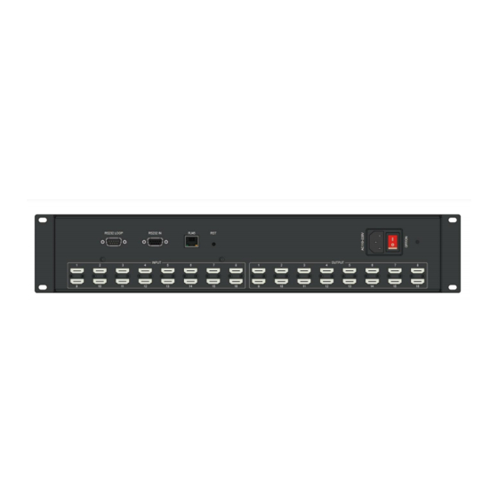
Page 11: Rear Pannel Introduction
Call the status saved before, press the button as: “number” + “LOAD” Noted:The matrix can save 9 status(number is to 9) 2.2Rear pannel introduction (1)Local RS232 loop out for daisy chain connection of multi matrix. (2)RS-232 serial port for control (3)TCP/IP control port (4)Reset button (5)Power supply jack... -
Page 12: Control Way
3 Controlling The Matrix 3.1 RS232 Control The matrix provides a standard RS232 serial port. The user can control the matrix by a PC or other controller. The matrix also provide the RS-232 loop out to transfer the command to other peripherals. Serial port default setting: Bit rate:9600,... -
Page 13: Rj45 Tcp/Ip Control
RS232 Connection Link the HDMI matrix to host control computer by using RS-232 cable, when connection is finished, you can control the matrix with the instructions we provided in the following chapter. 3.2 RJ45 TCP/IP Control The network port is based on the TCP/IP Network communication protocol and apply the remote control by Ethernet. - Page 14 In this system, the CAT5/5e cable is used to connect the matrix to network control equipment, each end of the line is fixed with the RJ-45 connector (commonly known as the crystal head). The standard line order is not random, the purpose is to ensure the symmetry of the cable connector layout, so that the interference between the cable and the cable can be offset.
-
Page 15: Software
4 Software 4.1 Switch (1) Connect to the matrix switcher by RS232. (2)Connect to the matrix switcher by TCP/IP (3)Select your operation, "AV" means switching audio and video "Video" means switching video "Audio" means switching audio "EDID" means read the EDID from input to output (4)Display executing the command (5) Input channel number (6 )Output channel number... -
Page 16: Keyboard
4.2 Keyboard We get the same function as the front panel on the software. Select your operation "Video","AV","Audio", press input(Up zone) and outputs(down... -
Page 17: Debug
zone) to switch the signal. Select "EDID" to read the input EDID to outputs. Select "Reboot MATRIX" to confirm/cancel reboot the matrix switcher. (2)Select the operation "All" and press the button number N ("1" to "16") to switch the input N to all output. -
Page 18: Demo
4.4 demo The software will auto send the command and switch the inputs to outputs. As above picture, "Start" is the input start channel, "End" is the input end channel. "Current Channel" means the current switching executing input channel. - Page 19 As above picture, "Start" is the output start channel, "End" is the output end channel. "Current Channel" means the current switching output channel. Click "start demo" ,the switching operation run one input to one output. from input "START" to output channel "START" ,delay time, next output, delay time, until the "END"...
-
Page 20: Command List
5 Command List 5.1 Switching command 1.One input to one output switch PC TO Matrix Function Matrix to PC Sample [X1]V[Y1]. 1 video input [X1] switch to output V:[X1]->[Y1]! 1V1. [Y1] [X1]V#. video input [X1] switch [X1] V Through! 1V#. corresponding output [Y1] [X1]#. -
Page 21: Enquiry
5.3 Enquiry PC TO Matrix Function Matrix to PC Sample Status[Y1]. Enquiry 1 channel audio & video V:[X1]->[X2]! Status1. status Status. Enquiry all channel audio & video V:[X1]->[X2]! Status. status ……... -
Page 22: Common Faults And Maintenance
6 Common Faults and Maintenance 1. Signal interference: the power supply must be connected to the power protection ground, and to ensure that the input and output devices with the same power protection ground. For the use of computer communication control users must ensure that the computer used and the device are connected to the power protection, and the same protection.
Need help?
Do you have a question about the VIS-PHD1616 and is the answer not in the manual?
Questions and answers