Table of Contents
Advertisement
Available languages
Available languages
Quick Links
Advertisement
Chapters
Table of Contents

Related Manuals for Videotec NXPTZHD


Summary of Contents for Videotec NXPTZHD
- Page 1 ITALIANO NXPTZHD HD PTZ camera for onshore/offshore, marine and industrial areas English - Instruction manual Italiano - Manuale di istruzioni Français - Manuel d’instructions Deutsch - Bedienungsanleitung Русский - Руководство по эксплуатации...
- Page 3 ENGLISH NXPTZHD HD PTZ camera for onshore/offshore, marine and industrial areas English - Instruction manual...
-
Page 5: Table Of Contents
Contents E N G L I S H 1 About this manual ......................5 1.1 Typographical conventions ..........................5 2 Notes on copyright and information on trademarks ..........5 3 Safety rules........................5 4 Identification ........................8 4.1 Product description and type designation..................... 8 4.2 Product marking .............................. - Page 6 8.2.7.1 Autopan Page.......................................22 8.2.7.2 Patrol Page ........................................23 8.2.7.3 Motions Recall Page ....................................23 8.2.8 Preset Parameters page ...............................23 8.2.9 Preset Parameters page (Advanced) ..........................23 8.2.10 Digital I/O Page ..................................24 8.2.11 Wiper ......................................24 8.2.12 Washer page ..................................24 8.2.13 Encoder Parameters page ..............................24 8.2.14 Camera Settings page ...............................25 8.2.15 Directional OSD Page ................................26 8.2.16 Video Analysis Page ................................27...
-
Page 7: About This Manual
1 About this manual 3 Safety rules Read all the documentation supplied carefully before CAUTION! The electrical system to which installing and using this unit. Keep the manual in a the unit is connected must be equipped convenient place for future reference. with a 20A max automatic bipolar circuit breaker. - Page 8 • The manufacturer declines all responsibility • Use a Class 2 listed UL tranformer, compliant with for any damage caused by an improper use the Standards in force, only for products marked of the appliances mentioned in this manual. UL, powered at 24Vac. Furthermore, the manufacturer reserves the right •...
- Page 9 • The separate protective earthing terminal provided • Only skilled personnel should carry out on this product shall be permanently connected maintenance on the device. When carrying out to earth. maintenance, the operator is exposed to the risk of electrocution and other hazards. •...
-
Page 10: Identification
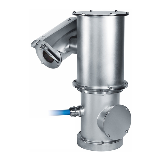
Pan & tilt devices have a label complying with CE markings. designation The NXPTZHD is an exceptional PTZ camera perfect for heavy-duty tasks and ideal to operate in the harshest and most corrosive environments, such as industrial and offshore/onshore marine applications. -
Page 11: Preparing The Product For Use
5 Preparing the product for 5.2 Unpacking When the product is delivered, make sure that the package is intact and that there are no signs that it has been dropped or scratched. Any change that is not expressly approved by the manufacturer will invalidate the If there are obvious signs of damage, contact the guarantee. -
Page 12: Preparatory Work Before Installation
5.5 Preparatory work before 5.5.1 Fixing to parapet or ceiling mount installation Attach the adapter (01) to the bottom of the unit using 4 stainless steel (A4 class 80) socket flat head cap screw M10 x 20mm (02). Use appropriate tools for the installation. The particular nature of the site where the Make sure the thread are free of dirt and debris. -
Page 13: Bracket Mounting
5.5.2 Bracket mounting 5.5.3 Fixing the unit to the pole mount adapter or corner mount adapter The bracket can be fixed to the vertical wall. Use screws and wall fixing devices that can bear at least To install the product on a pole or at a wall corner, four times the weight of the unit. -
Page 14: Fixing With Corner Adapter
5.5.3.2 Fixing with corner adapter 5.5.4 Sunshield mounting Fix the wall bracket to the corner mount adapter You can fix the sunshield to the housing using the using 4 washers, 4 stainless steel grower washers screws supplied. 4 hexagon stainless steel bolts (A4 class 80) Apply a generous amount of thread locking M10x30mm. -
Page 15: Installation
At start up the system makes some automatic calibration movements: do not stand near the device when it is powered. VIDEOTEC strongly recommend to test the device configuration and performance before putting it in the final installation site. The product is equipped with a multicore cable that allows connections to be made. -
Page 16: Connection Of The Power Supply Line
6.3 Connection of the power 6.4 Connection of the Ethernet supply line cable Electrical connections must be performed Do not connect RS-485 cable and the video with the power supply disconnected and cable when using an IP camera. the circuit-breaker open. The Ethernet cable shield on the operator When commencing installation make sure side must always be earthed via the... -
Page 17: Alarm And Relay Connections
6.5 Alarm and relay connections 6.5.2 Relay connection The relay is usable with the specifications The unit is equipped with the alarms and relays described below. Working voltage: up indicated in the table. to 30Vac or 60Vdc. Current: 1A max. Use ALARM AND RELAY CONNECTIONS suitable cable sections with the following Cable color... -
Page 18: Configuration
The product can work via ONVIF or TCAM After preparing and configuring the product, now (VIDEOTEC) protocol. In the event the proceed with the IP settings (6.4 Connection of the ONVIF protocol is used, make sure to set the Ethernet cable, page 14). - Page 19 Click Add. The camera will be available in the device list (Camera list) and can be displayed by dragging-and-dropping the icon onto one of the squares not used. Fig. 16 Fig. 14 To display the cameras on different computers, install Assign a name to the camera and to the unit.
- Page 20 A window appears to add the servers to which connect to by pressing the Add button. Fig. 19 Click Ok to go back to the display program. It will Fig. 18 be possible to see the cameras by dragging-and- Once the server has been added it must be registered dropping as per the TVMS server.
-
Page 21: Web Interface
8.2 Web interface 8.2.2 User Controls page To control the device through the browser, select the During the first connection assign an User Control entry. A new window will open with a address other than 192.168.10.100. virtual keyboard to enter commands. Browsers supported: Microsoft Internet Explorer, Microsoft Edge, Google Chrome, Mozilla Firefox. -
Page 22: Device Parameters Page
8.2.3 Device Parameters Page • Focus Near/Focus Far In the Device Settings menu, it is possible to view the information on the product code, the serial number, the MAC address, the firmware version and the hardware review. Fig. 24 • Wiper/Washer: If a tank was installed and configured, the command activates the wiper and the wash procedure. -
Page 23: Network Configuration Page
8.2.5 Network Configuration page NTP Server: It is also possible to specify if the device needs to be synchronised with an external NTP From menu entry Network Configuration it is possible (Network Time Protocol) server. to change the setting of the device. It is possible •... -
Page 24: Movement Parameters Page
8.2.7 Movement Parameters page • Tilt Limits: Enables the limits of Tilt. • Tilt Start: Sets the start limit of Tilt. From menu entry Movement Parameters it is possible to control, via web, all Pan & Tilt parameters. • Tilt End: Sets the end limit of Tilt. •... -
Page 25: Patrol Page
8.2.7.2 Patrol Page 8.2.8 Preset Parameters page From menu entry Patrol it is possible to specify the From menu entry Preset Parameters a number of preset patrol start and end. Patrol is a function that parameters relative to the presets can be configured: moves the unit between two or more presets. -
Page 26: Digital I/O Page
8.2.10 Digital I/O Page 8.2.13 Encoder Parameters page From menu entry Digital I/O it is possible to configure In the Encoder Settings menu, it is possible to the digital channels available in the device. What configure up to 4 video flows of the device. The first follows is a brief description of the configurable flow must be compressed with the algorithm H.264/ parameters for each digital input. -
Page 27: Camera Settings Page
8.2.14 Camera Settings page • Other: It allows setting other values: Image Mirror, Noise Reduction, Wide Dynamic (Visibility The camera integrated in the device can be Enhancer), High Resolution, Aperture Control, configured under the Camera Parameters menu: Defog, Highlight Correction. •... -
Page 28: Directional Osd Page
8.2.15 Directional OSD Page The device supports definition of four pan regions and information text video display based on the position of the Pan & Tilt. The four areas can be Start overlapped. You can define the following settings for each area: 0°... -
Page 29: Video Analysis Page
8.2.16 Video Analysis Page 8.2.18 Factory Default The device can be configured to emit motion If the access password is no longer detection alarms using ONVIF events. available, follow the procedure to reset to This page allows you to define the following settings: default factory settings. -
Page 30: Accessories
9 Accessories 10 Instructions for normal operation For further details on configuration and use, refer to the relative manual. Do not use the wiper if the outside temperature is below 0°C or in case of ice. 9.1 Washer The P&T can be equipped with an external pump that 10.1 Special controls supplies water for the glass to be cleaned. -
Page 31: Maintenance
24Vac, 50/60Hz T 4A H 250V 5x20 T 4A H 250V 5x20 Whenever replacing the parts as indicated, always use VIDEOTEC original spare parts 120Vac, 50/60Hz T 2A L 250V 5x20 T 4A H 250V 5x20 and meticulously follow the maintenance... -
Page 32: Cleaning
12 Cleaning 14 Troubleshooting Frequency will depend on the type of Contact an authorized support centre if the environment in which the product is used. problems listed below persist or you have any other issues that are not described 12.1 Cleaning the glass here. -
Page 33: Technical Data
15 Technical data 15.4 Video Video encoder 15.1 Mechanical • Communication protocol: ONVIF, Profile S AISI 316L stainless steel construction • Device configuration: TCP/IPv4-IPv6, UDP/IPv4- External surfaces micro-shot peened in silicon and IPv6, HTTP, HTTPS, NTP, DHCP, WSDISCOVERY, QoS, electro-polished DSCP, IGMP (Multicast), SOAP, DNS, SNMP Pre-wired multipolar cable (3m (9.8ft)) •... -
Page 34: Cameras
15.6 Cameras 15.7 Environment Day/Night Full HD 30x For installation indoors and outdoors Resolution: Full HD 1080p (1920x1080) Operating temperature: from -40°C (-40°F) up to +60°C (140°F) Image Device: 1/2.8 type Exmor™ CMOS sensor 15.8 Certifications Effective Pixels: approx. 2.38 Megapixels Minimum Illumination, colour (ICR-OFF): Electrical safety (CE): EN60950-1, IEC60950-1 •... -
Page 35: Technical Drawings
16 Technical drawings The dimensions of the drawings are in millimetres. Ø 138 N°4 M10 Fig. 51 NXPTZHD. MNVCNXPTZHD_1801_EN... - Page 36 Email: info@videotec.com Tel. +33 1 60491816 - Fax +33 1 69284736 Email: info.fr@videotec.com Asia Pacific Videotec (HK) Ltd Americas Videotec Security, Inc. Flat 8, 19/F. On Dak Industrial Building, No. 2-6 Wah Sing Street Gateway Industrial Park, 35 Gateway Drive, Suite 100 Kwai Chung, New Territories - Hong Kong Plattsburgh, NY 12901 - U.S.A.
- Page 37 ITALIANO NXPTZHD Telecamera PTZ HD per applicazioni onshore/ offshore, marittime e industriali Italiano - Manuale di istruzioni...
- Page 39 Sommario I T A L I A N O 1 Informazioni sul presente manuale ................5 1.1 Convenzioni tipografiche ............................. 5 2 Note sul copyright e informazioni sui marchi commerciali ........5 3 Norme di sicurezza ......................5 4 Identificazione ....................... 8 4.1 Descrizione e designazione del prodotto .......................
- Page 40 8.2.7.1 Pagina Autopan ......................................22 8.2.7.2 Pagina Patrol .........................................23 8.2.7.3 Pagina Richiamo Movimenti ...................................23 8.2.8 Pagina Parametri Preset ..............................23 8.2.9 Pagina Parametri Preset (Avanzato) ..........................23 8.2.10 Pagina I/O Digitali ................................24 8.2.11 Wiper ......................................24 8.2.12 Pagina Washer ..................................24 8.2.13 Pagina Parametri Encoder ..............................24 8.2.14 Pagina Parametri Telecamera ............................25 8.2.15 Pagina OSD Direzionale ..............................26 8.2.16 Pagina Analisi Video ................................27...
-
Page 41: Informazioni Sul Presente Manuale
1 Informazioni sul presente 3 Norme di sicurezza manuale ATTENZIONE! L’impianto elettrico al quale è collegata l’unità deve essere dotato di Prima di installare e utilizzare questa unità, leggere un interruttore di protezione bipolare attentamente tutta la documentazione fornita. Tenere automatico da 20A max. - Page 42 • Il produttore declina ogni responsabilità per • Per i prodotti marcati UL alimentati a 24Vac, eventuali danni derivanti da un uso improprio utilizzare un trasformatore UL listed Classe 2, delle apparecchiature menzionate in questo conforme alle normative vigenti. manuale. Si riserva inoltre il diritto di modificarne il •...
- Page 43 • Il terminale di terra disponibile nel prodotto deve • La manutenzione del dispositivo deve essere essere collegato permanentemente alla terra. eseguita solo da personale qualificato. Durante le operazioni di manutenzione l'operatore è esposto • Per assicurare la protezione contro il rischio di al rischio di folgorazione o ad altri pericoli.
-
Page 44: Identificazione
Non effettuare per nessun motivo alterazioni o collegamenti non previsti in questo manuale. L'uso NXPTZHD é sempre fornita di tergicristallo integrato; di apparecchi non idonei può portare a gravi pericoli é disponibile un'ampia scelta di taniche con pompa per la sicurezza del personale e dell'impianto. -
Page 45: Preparazione Del Prodotto Per L'utilizzo
5 Preparazione del prodotto 5.2 Disimballaggio per l'utilizzo Alla consegna del prodotto verificare che l'imballo sia integro e non presenti segni evidenti di cadute o abrasioni. Qualsiasi intervento non espressamente approvato dal costruttore fa decadere la In caso di danni evidenti all'imballo contattare garanzia. -
Page 46: Lavoro Preparatorio Prima Dell'installazione
5.5 Lavoro preparatorio prima 5.5.1 Fissaggio a parapetto o a soffitto dell’installazione Collegare l’adattatore (01) al fondo dell’unità utilizzando 4 viti a testa svasata piana (02) con esagono incassato M10x20mm in acciaio inox (A4 Eseguire l’installazione utilizzando utensili classe 80). adeguati. -
Page 47: Fissaggio Con Staffa
5.5.2 Fissaggio con staffa 5.5.3 Fissaggio con imbracatura da palo o modulo adattatore angolare Il supporto può essere fissato direttamente ad un muro verticale. Utilizzare viti e dispositivi di fissaggio Per installare il prodotto su imbracatura da palo o in a muro che possono sostenere un peso almeno 4 corrispondenza di un angolo prima di tutto fissare volte superiore a quello dell’unità. -
Page 48: Fissaggio Con Modulo Angolare
5.5.3.2 Fissaggio con modulo angolare 5.5.4 Fissaggio del tettuccio Per fissare la staffa di supporto a muro al modulo È possibile fissare il tettuccio alla custodia utilizzando adattatore angolare, utilizzare 4 rondelle piane, la viteria fornita in dotazione. 4 rondelle grower in acciaio inox e 4 viti a testa Applicare una buona quantità... -
Page 49: Installazione
All’avvio il sistema esegue una serie di movimenti di calibrazione automatici: non sostare nei pressi dell’apparecchio quando viene acceso. VIDEOTEC raccomanda di testare la configurazione e le prestazioni dell’apparecchio prima di collocarlo nel sito di installazione definitivo. Il prodotto è provvisto di un cavo multipolare che permette di effettuare i Fig. -
Page 50: Collegamento Della Linea Di Alimentazione
6.3 Collegamento della linea di 6.4 Collegamento del cavo di rete alimentazione Ethernet Eseguire le connessioni elettriche in Non collegare il cavo RS-485 e il cavo video assenza di alimentazione e con dispositivo quando si utilizza una telecamera IP. di sezionamento aperto. La calza del cavo Ethernet dal lato All’atto dell’installazione controllare che utilizzatore deve essere sempre collegata a... -
Page 51: Collegamento Degli Allarmi E Dei Relè
6.5 Collegamento degli allarmi e 6.5.2 Collegamento del relè dei relè Il relè è utilizzabile con le specifiche descritte di seguito. Tensione di lavoro: L’unità è dotata degli allarmi e dei relè riportati in fino a 30Vac oppure 60Vdc. Corrente: 1A tabella. -
Page 52: Configurazione
Il prodotto può funzionare mediante Dopo aver predisposto e configurato il prodotto, protocollo ONVIF o TCAM (VIDEOTEC). Se procedere alla configurazione dei parametri IP (6.4 si utilizza il protocollo ONVIF, assicurarsi Collegamento del cavo di rete Ethernet, pagina 14). - Page 53 Cliccare il tasto Add. La telecamera sarà disponibile nell'elenco dei dispositivi (Camera list) e potrà essere visualizzata effettuando un drag and drop dell'icona su uno dei riquadri non utilizzati. Fig. 14 Fig. 16 Assegnare un nome alla telecamera ed al gruppo. Per visualizzare le telecamere su più...
- Page 54 Verrà visualizzata una finestra dove sarà possibile aggiungere i server cui collegarsi premendo il bottone Add. Fig. 19 Cliccare Ok per tornare al programma di visualizzazione. Sarà possibile a questo punto vedere Fig. 18 le videocamere, effettuando drag and drop come nel Dopo aver aggiunto il server sarà...
-
Page 55: Interfaccia Web
8.2 Interfaccia web 8.2.2 Pagina Controlli Utente Per controllare il dispositivo via browser, selezionare Alla prima connessione assegnare un la voce Controlli Utente. Si aprirà una nuova finestra indirizzo diverso da 192.168.10.100. con una tastiera virtuale per inviare i comandi. Browser supportati: Microsoft Internet Explorer, Microsoft Edge, Google Chrome, Mozilla Firefox. -
Page 56: Pagina Parametri Dispositivo
8.2.3 Pagina Parametri Dispositivo • Focus Near/Focus Far Alla voce del menu Parametri Dispositivo è possibile visualizzare le informazioni sul codice prodotto, il numero di serie, l'indirizzo MAC, la versione dei firmware e la revisione dell'hardware. Fig. 24 • Wiper/Washer: Se è stata installata e configurata una tanica, il comando aziona il tergicristallo e la procedura di lavaggio. -
Page 57: Pagina Configurazione Rete
8.2.5 Pagina Configurazione Rete Server NTP: È possibile inoltre specificare se il dispositivo debba sincronizzarsi con un server NTP Alla voce del menu Configurazione Rete è possibile (Network Time Protocol) esterno. cambiare l'impostazione di rete del dispositivo. È • DISABILITATO: Selezionare questa opzione se non possibile decidere se il dispositivo debba avere un si desidera sincronizzare data e ora del dispositivo. -
Page 58: Pagina Parametri Movimento
8.2.7 Pagina Parametri Movimento • Limiti Tilt: Abilita i limiti del Tilt. • Tilt Inizio: Imposta il limite iniziale del Tilt. Alla voce del menu Parametri Movimento è possibile controllare via web tutti i parametri del brandeggio. • Tilt Fine: Imposta il limite finale del Tilt. •... -
Page 59: Pagina Patrol
8.2.7.2 Pagina Patrol 8.2.8 Pagina Parametri Preset Alla voce del menu Patrol è possibile specificare Alla voce del menu Parametri Preset sono il preset di inizio e di fine del patrol. Patrol è una configurabili alcuni parametri relativi ai preset: funzione che fa muovere l'unità... -
Page 60: Pagina I/O Digitali
8.2.10 Pagina I/O Digitali 8.2.13 Pagina Parametri Encoder Alla voce del menu I/O Digitali è possibile configurare Alla voce del menù Parametri Encoder è possibile i canali digitali presenti nel dispositivo. Segue una configurare fino a 4 flussi video del dispositivo. Il breve descrizione dei parametri configurabili per primo flusso è... -
Page 61: Pagina Parametri Telecamera
8.2.14 Pagina Parametri Telecamera • Altro: Permette di impostare altri valori: Immagine Speculare, Riduzione Rumore, Wide Dynamic Alla voce del menu Parametri Camera è possibile (Visibility Enhancer), Alta Risoluzione, Controllo configurare la telecamera integrata nel dispositivo: Apertura, Defog, Correzione Sovraesposizione. •... -
Page 62: Pagina Osd Direzionale
8.2.15 Pagina OSD Direzionale Il dispositivo supporta la definizione di quattro regioni pan e la visualizzazione a video di testo informativo in base alla posizione del brandeggio. Le Start quattro aree possono essere sovrapposte. È possibile definire per ogni area i seguenti parametri: 0°... -
Page 63: Pagina Analisi Video
8.2.16 Pagina Analisi Video 8.2.18 Factory Default Il dispositivo può essere configurato affinché emetta Se la password di accesso non è più degli allarmi di motion detection mediante eventi disponibile, è possibile ripristinare le ONVIF. impostazioni di fabbrica tramite una In questa pagina è... -
Page 64: Accessori
9 Accessori 10 Istruzioni di funzionamento ordinario Per ulteriori dettagli sulla configurazione e l’utilizzo fare riferimento al manuale del Non utilizzare il tergicristallo se la relativo accessorio. temperatura esterna è inferiore a 0°C o in 9.1 Impianto di lavaggio presenza di ghiaccio. Il brandeggio può... -
Page 65: Manutenzione
In caso di danneggiamento la sostituzione SOSTITUZIONE DEI FUSIBILI o riparazione delle parti interessate deve Tensione di Fusibile (FUS1) Fusibile (FUS2) essere eseguita da VIDEOTEC o sotto la sua alimentazione supervisione. 24Vac, 50/60Hz T 4A H 250V 5x20 T 4A H 250V 5x20... -
Page 66: Pulizia
12 Pulizia 14 Risoluzione dei problemi La frequenza di interventi dipende dalla Per qualunque problematica non descritta tipologia dell’ambiente in cui è utilizzato il o se i problemi elencati in seguito prodotto. dovessero persistere, contattare il centro di assistenza autorizzato. 12.1 Pulizia del vetro PROBLEMA Il prodotto non si accende. -
Page 67: Dati Tecnici
15 Dati tecnici 15.4 Video Encoder video 15.1 Meccanica • Protocollo di comunicazione: ONVIF, Profilo S Costruzione in acciaio Inox AISI 316L • Configurazione del dispositivo: TCP/IPv4- Superfici esterne micropallinate al silicio ed IPv6, UDP/IPv4-IPv6, HTTP, HTTPS, NTP, DHCP, elettrolucidate WSDISCOVERY, QoS, DSCP, IGMP (Multicast), SOAP, DNS, SNMP Cavo multipolare preinstallato (3m) -
Page 68: Telecamere
15.6 Telecamere 15.7 Ambiente Day/Night Full HD 30x Installazione per interni ed esterni Risoluzione: Full HD 1080p (1920x1080) Temperatura di esercizio: da -40°C fino a +60°C Sensore di immagine: 1/2.8 type Exmor™ CMOS 15.8 Certificazioni sensor Sicurezza elettrica (CE): EN60950-1, IEC60950-1 Pixels Effettivi: appross. -
Page 69: Disegni Tecnici
16 Disegni tecnici Le dimensioni dei disegni sono espresse in millimetri. Ø 138 N°4 M10 Fig. 51 NXPTZHD. MNVCNXPTZHD_1801_IT... - Page 70 Email: info@videotec.com Tel. +33 1 60491816 - Fax +33 1 69284736 Email: info.fr@videotec.com Asia Pacific Videotec (HK) Ltd Americas Videotec Security, Inc. Flat 8, 19/F. On Dak Industrial Building, No. 2-6 Wah Sing Street Gateway Industrial Park, 35 Gateway Drive, Suite 100 Kwai Chung, New Territories - Hong Kong Plattsburgh, NY 12901 - U.S.A.
- Page 71 FRANÇAIS NXPTZHD Caméra PTZ HD pour applications onshore/ offshore, maritime et industrielles Français - Manuel d’instructions...
- Page 73 Sommaire F R A N Ç A I S 1 À propos de ce mode d’emploi ..................5 1.1 Conventions typographiques ..........................5 2 Notes sur le copyright et informations sur les marques de commerce ..... 5 3 Normes de securité ......................5 4 Identification ........................
- Page 74 8.2.7.1 Page Autopan.......................................22 8.2.7.2 Page Patrol ........................................23 8.2.7.3 Page Rappel Mouvements ..................................23 8.2.8 Page Paramètres Preset ...............................23 8.2.9 Page Paramètres Preset (Avancé) ............................23 8.2.10 Page I/O Digitaux ................................24 8.2.11 Wiper ......................................24 8.2.12 Page Washer ..................................24 8.2.13 Page Paramètres Encoder ..............................24 8.2.14 Page Paramètres Caméra ..............................25 8.2.15 Page OSD Directionnelle ..............................26 8.2.16 Page Analyses Vidéo ................................27...
-
Page 75: À Propos De Ce Mode D'emploi
1 À propos de ce mode 3 Normes de securité d’emploi ATTENTION! Le circuit électrique auquel l'unité est reliée doit être équipé d'un Avant d'installer et d'utiliser cette unité, lire interrupteur de protection bipolaire attentivement toute la documentation fournie. automatique de 20A max. Cet interrupteur Garder le manuel à... - Page 76 • Le fabricant décline toute responsabilité pour les • Il faut, uniquement pour les produits marqués UL dommages éventuels dus à une utilisation non alimentés à 24Vac, utiliser un transformateur UL appropriée des appareils mentionnés dans ce listed Classe 2, conforme aux normes en vigueur. manuel.
- Page 77 • La borne de terre disponible dans le produit doit • L'entretien du dispositif doit uniquement être être connecté en permanence à la terre. effectué par un personnel qualifié. Durant les opérations d'entretien, l'opérateur est exposé au • Pour assurer la protection contre le risque risque d'électrocution ou autres.
-
Page 78: Identification
4.1 Description et désignation du Les tourelles portent un étiquette conforme au marquage CE. produit NXPTZHD est une caméra PTZ exceptionnelle qui garantit de hautes performances fonctionnelles pour l’utilisation en milieux hautement corrosifs comme les milieux industriels et marins offshore/onshore. -
Page 79: Préparation Du Produit En Vue De L'utilisation
5 Préparation du produit en 5.2 Déballage vue de l’utilisation Lors de la livraison du produit, vérifier que l’emballage est en bon état et l’absence de tout signe évident de chute ou d’abrasion. Toute modification non approuvée expressément par le fabricant entraînera En cas de dommages évidents, contacter l’annulation de la garantie. -
Page 80: Opérations À Effectuer Avant L'installation
5.5 Opérations à effectuer avant 5.5.1 Fixation sur parapet ou plafond l’installation Brancher l'adaptateur (01) au fond de l'unité en utilisant 4 vis à tête plate évasée (02) avec hexagone encastré M10x20mm en acier inox (A4 classe 80). Effectuer l'installation en utilisant des outils adéquats. -
Page 81: Fixation Avec Étrier
5.5.2 Fixation avec étrier 5.5.3 Fixation avec poteau ou module adaptateur angulaire Le support peut être fixé directement sur un mur vertical. Utiliser des vis et des dispositifs de fixation Pour installer le produit sur la fixation pour poteau ou murale pouvant soutenir un poids au moins 4 fois face à... -
Page 82: Fixation Avec Module Angulaire
5.5.3.2 Fixation avec module angulaire 5.5.4 Fixation du double toit Pour fixer l'étrier de support mural au module Il est possible de fixer le toit au caisson en utilisant les adaptateur angulaire, utiliser 4 rondelles pleines, vis fournies. 4 rondelles élastiques en acier inox et 4 vis à Appliquer une bonne quantité... -
Page 83: Installation
VIDEOTEC conseille de tester la configuration et les performances de l'appareils avant de placer celui-ci sur le lieu d'installation définitive. Le produit est muni d'un câble multipolaire Fig. -
Page 84: Connexion De La Ligne D'alimentation
6.3 Connexion de la ligne 6.4 Branchement du câble de d'alimentation réseau Ethernet Il faut effectuer les connexions électriques Ne pas brancher le câble RS-485 et le câble en absence d'alimentation et lorsque le vidéo lors de l'utilisation d'une caméra IP. dispositif de sectionnement ouvert. -
Page 85: Branchement Aux Alarmes Et Aux Relais
6.5 Branchement aux alarmes et 6.5.2 Branchement du relais aux relais Le relais est utilisable avec les spécifications décrites ci-après. Tension de travail: jusqu'à L’unité est équipée des alarmes et des relais reportés 30Vac ou 60Vdc. Courant: 1A max. Utiliser dans le tableau. -
Page 86: Configuration
8.1.2 Procédure de configuration par Le produit peut fonctionner par protocole l'intermédiaire du logiciel ONVIF ou TCAM (VIDEOTEC). En cas Après avoir prédisposé et configuré le produit, d'utilisation du protocole ONVIF, s'assurer procéder à la configuration des paramètres IP (6.4 de paramétrer correctement l'heure du... - Page 87 Cliquer sur la touche Add. La caméra sera disponible dans la liste des dispositifs (Camera list) et pourra être affichée en effectuant un drag and drop de l'icône sur l'un des encadrés non utilisés. Fig. 14 Fig. 16 Attribuer un nom à la caméra et au groupe. Pour afficher les caméras sur plusieurs ordinateurs Sélectionner le protocole ONVIF ou TCAM et il faut installer le TVMS client et l'utiliser pour...
- Page 88 Une fenêtre où il sera possible d'ajouter les serveurs auxquels se raccorder s'affichera en appuyant sur le bouton Add. Fig. 19 Cliquer sur Ok pour retourner au programme d'affichage. Il sera alors possible de voir les caméras Fig. 18 en effectuant drag and drop comme dans le cas du Après avoir ajouté...
-
Page 89: Interface Web
8.2 Interface web 8.2.2 Page Contrôles Utilisateur Pour contrôler la dispositif par browser, sélectionner À la première connexion, donner une la mention Contrôle Utilisateur. Une nouvelle fenêtre adresse différente de 192.168.10.100. s'ouvrira, avec un clavier virtuel pour sélectionner les commandes. Logiciels de navigation supportés: Microsoft Internet Explorer, Microsoft Edge, Google Chrome, Mozilla Firefox. -
Page 90: Page Paramètres Dispositif
8.2.3 Page Paramètres Dispositif • Focus Near/Focus Far À la rubrique du menu Paramètres Dispositif, on peut afficher les informations sur le code produit, le numéro de série, l'adresse MAC, la version des firmwares et la révision du matériel informatique. Fig. -
Page 91: Page Configuration Réseau
8.2.5 Page Configuration Réseau Serveur NTP: Il est également possible de mentionner si le dispositif doit se synchroniser avec A la mention du menu Configuration Réseau il est un serveur NTP (Network Time Protocol) externe. possible de changer la configuration de réseau de •... -
Page 92: Page Paramètres Mouvement
8.2.7 Page Paramètres Mouvement • Limites Tilt: Configure la limite initiale de Tilt. • Tilt Début: Configure la limite initiale de Tilt. A la mention du menu Paramètres Mouvement il est possible de contrôler par web tous les paramètres de •... -
Page 93: Page Patrol
8.2.7.2 Page Patrol 8.2.8 Page Paramètres Preset A la mention du menu Patrol il est possible d'indiquer A la mention du menu Paramètres Preset on peut le preset de début et de fin du patrol. Patrol est une configurer certains paramètres concernant les preset: fonction qui déplace l'unité... -
Page 94: Page I/O Digitaux
8.2.10 Page I/O Digitaux 8.2.13 Page Paramètres Encoder Dans la carte I/O Digitaux il est possible de configurer À la rubrique du menu Paramètres Encodeur, il les canaux digitaux présents dans le dispositif. Il y a est possible de configurer jusqu'à 4 flux vidéo ci-dessous une courte description des paramètres du dispositif. -
Page 95: Page Paramètres Caméra
8.2.14 Page Paramètres Caméra • Autre: Cela permet d'installer d'autres valeurs: Image Renversée, Noise Reduction, Wide Dynamic Dans le menu Paramètres Caméra il est possible de (Visibility Enhancer), Haute Resolution, Contrôle De configurer la caméra intégrée au dispositif: L'ouverture, Defog, Correction De La Surexposition. •... -
Page 96: Page Osd Directionnelle
8.2.15 Page OSD Directionnelle Le dispositif supporte la définition de quatre régions de rotation (pan) et l'affichage vidéo d'un texte d'information en fonction de la position de la tourelle. Start Les quatre aires peuvent être superposées. Il est possible de définir pour chaque aire les 0°... -
Page 97: Page Analyses Vidéo
8.2.16 Page Analyses Vidéo 8.2.18 Factory Default Le dispositif peut être configuré pour émettre Si le mot de passe d'accès n'est plus des alarmes de détection de mouvement par disponible, il est possible de rétablir les l'intermédiaire d'événements ONVIF. programmations d'usine à travers une Dans cette page, il est possible de définir les procédure de réinitialisation. -
Page 98: Accessoires
9 Accessoires 10 Instructions de fonctionnement courant Pour de plus amples informations sur la configuration et l'utilisation, consulter le Ne pas utiliser l’essuie-glace avec manuel de l'accessoire correspondant. température extérieure inférieure à 0°C ou 9.1 Système de lavage en cas de givre. La tourelle peut être équipée d'une pompe extérieure 10.1 Commandes spéciales qui fournit de l'eau pour le nettoyage de la vitre. -
Page 99: Entretien
Lorsque vous contactez le service technique de VIDEOTEC, il est nécessaire de fournir le numéro de série et le code d'identification de l'appareil. Fig. 50 11.1 Maintenance ordinaire (à... -
Page 100: Nettoyage
12 Nettoyage 14 Dépannage La fréquence des interventions dépend Pour toute problématique que ce soit du type d’environnement dans lequel le non décrite ou si les problèmes énumérés caisson est utilisé. ci-après persistent, contacter le centre d'assistance autorisé. 12.1 Nettoyage de la vitre PROBLÈME Le produit ne s'allume pas. -
Page 101: Données Techniques
15 Données techniques 15.4 Vidéo Encodeur vidéo 15.1 Mécanique • Protocole de communication: ONVIF, Profil S Construction en acier inox AISI 316L • Configuration du dispositif: TCP/IPv4-IPv6, UDP/ Surfaces externes microbillées au silicium et IPv4-IPv6, HTTP, HTTPS, NTP, DHCP, WSDISCOVERY, électropolies QoS, DSCP, IGMP (Multicast), SOAP, DNS, SNMP Câble multipolaire préinstallé... -
Page 102: Caméras
15.6 Caméras 15.7 Environnement Day/Night Full HD 30x Installation d'intérieur et d'extérieur Résolution: Full HD 1080p (1920x1080) Température de fonctionnement: de -40°C jusqu'à +60°C Capteur d'image: 1/2.8 type Exmor™ CMOS sensor 15.8 Certifications Pixels effectifs: environ 2.38 Megapixels Éclairage minimum, couleur (ICR-OFF): Sécurité... -
Page 103: Dessins Techniques
16 Dessins techniques Les dimensions des dessins sont exprimées en millimètres. Ø 138 N°4 M10 Fig. 51 NXPTZHD. MNVCNXPTZHD_1801_FR... - Page 104 Email: info@videotec.com Tel. +33 1 60491816 - Fax +33 1 69284736 Email: info.fr@videotec.com Asia Pacific Videotec (HK) Ltd Americas Videotec Security, Inc. Flat 8, 19/F. On Dak Industrial Building, No. 2-6 Wah Sing Street Gateway Industrial Park, 35 Gateway Drive, Suite 100 Kwai Chung, New Territories - Hong Kong Plattsburgh, NY 12901 - U.S.A.
- Page 105 DEUTSCH NXPTZHD HD PTZ Kamera für onshore/offshore, Marine und Industrie Deutsch - Bedienungsanleitung...
- Page 107 Inhaltsverzeichnis D E U T S C H 1 Allgemeines ........................5 1.1 Schreibweisen ................................5 2 Anmerkungen zum Copyright und Informationen zu den Handelsmarken ..... 5 3 Sicherheitsnormen ......................5 4 Identifizierung ....................... 8 4.1 Beschreibung und Bezeichnung des Produktes ................... 8 4.2 Kennzeichnung des Produkts..........................
- Page 108 8.2.7.1 Autopan Seite.......................................22 8.2.7.2 Patrol Seite ........................................23 8.2.7.3 Bewegungsanforderung Seite ................................23 8.2.8 Preset-Parameter Seite ................................23 8.2.9 Preset-Parameter Seite (Fortgeschritten) ........................23 8.2.10 Digitale I/O Seite ..................................24 8.2.11 Wiper ......................................24 8.2.12 Washer Seite ..................................24 8.2.13 Encodereinstellungen Seite ............................24 8.2.14 Kamera-Parameter Seite ..............................25 8.2.15 Seite OSD Richtung ................................26 8.2.16 Seite Videoanalysen ................................27 8.2.17 Werkzeuge Seite ..................................27...
-
Page 109: Allgemeines
1 Allgemeines 3 Sicherheitsnormen Vor Installation und Anwendung der Einheit ist die ACHTUNG! Die elektrische Anlage, an gesamte gelieferte Dokumentation aufmerksam zu der die Einheit angeschlossen ist, muss lesen. Zum späteren Nachschlagen das Handbuch in mit einem automatischen zweipoligen Reichweite aufbewahren. Schutzschalter 20A max ausgestattet sein. - Page 110 • Der Hersteller lehnt jede Haftung für eventuelle • Lediglich für die Produkte mit UL - Markierung mit Schäden ab, die aufgrund unsachgemäßer 24Vac - Versorgung ein UL - Speisetransformator Anwendung der in diesem Handbuch erwähnten der Klasse 2 verwenden, welches den geltenden Geräte entstanden ist.
- Page 111 • Der im Gerät verfügbare Erdungsanschluss muss • Die Wartung der Einrichtung ist Fachleuten ständig geerdet sein. vorbehalten. Während der Wartungsarbeiten ist die tätige Person der Gefahr von Stromschlägen und • Damit ein ständiger Brandschutz garantiert wird, anderen Gefahren ausgesetzt. sind die Sicherungen nur in dem gleichen Typ und Wert zu ersetzen.
-
Page 112: Identifizierung
Handbuch nicht genannt sind. Der Gebrauch Temperatur. ungeeigneten Geräts kann die Sicherheit des Personals und der Anlage schwer gefährden. Die NXPTZHD ist immer mit integriertem Wischer geliefert; große Auswahl an Tanks mit Waschpumpe mit unterschiedlichen Kapazitäten und Förderhöhen verfügbar. -
Page 113: Vorbereitung Des Produktes Auf Den Gebrauch
5 Vorbereitung des 5.2 Entfernen der Verpackung Produktes auf den Gebrauch Bei der Lieferung des Produktes ist zu prüfen, ob die Verpackung intakt ist oder offensichtliche Anzeichen von Stürzen oder Abrieb aufweist. Jede vom Hersteller nicht ausdrücklich genehmigte Veränderung führt zum Verfall Bei offensichtlichen Schadensspuren an der der Gewährleistungsrechte. -
Page 114: Auf Die Installation Vorbereitende Tätigkeiten
5.5 Auf die Installation 5.5.1 Befestigung an der Brüstung oder an der Decke vorbereitende Tätigkeiten Den Adapter (01) unten an der Einheit anschließen; dazu die 4 Flachsenkschrauben (02) mit Die Installation mit geeigneten Werkzeugen Innensechskant M10x20mm aus Edelstahl Inox (A4 ausführen. -
Page 115: Befestigung Mit Bügel
5.5.2 Befestigung mit Bügel 5.5.3 Befestigung durch Mastverseilung oder Winkeladaptermodul Die Halterung kann direkt an einer vertikalen Wand befestigt werden. Schrauben und Um das Produkt an der Mastverseilung zu installieren Wandbefestigungsvorrichtungen verwenden, die bzw. in Übereinstimmung eines Winkels muss man einem Gewicht standhalten können, das mindestens in erster Linie die Einheit an der Wandhalterung viermal größer als das der Einheit ist. -
Page 116: Befestigung Mit Winkelmodul
5.5.3.2 Befestigung mit Winkelmodul 5.5.4 Befestigung des Dachs Um den Halterungsbügel am Winkeladaptermodul Es ist möglich, das Sonnenschutzdach am Gehäuse zu befestigen verwendet man 4 flache zu befestigen. Hierzu die mitgelieferten Schrauben Unterlegescheiben, 4 Grower-Unterlegescheiben aus verwenden. Edelstahl und 4 Sechskantschrauben aus Edelstahl Eine ausreichende Menge an Schraubensicherung (A4 Klasse 80) M10x30mm. -
Page 117: Installation
Beim Start führt das System eine Reihe von automatischen Kalibrierbewegungen aus: Halten Sie sich nicht in der Nähe des Gerätes auf, wenn es eingeschaltet wird. VIDEOTEC empfiehlt, vor der endgültigen Montage am Installationsort die Konfiguration und die Leistungen des Gerätes zu prüfen. -
Page 118: Anschluss Der Stromversorgung
6.3 Anschluss der 6.4 Anschluss der Ethernet-Kabel Stromversorgung Das Kabel RS-485 und das Videokabel nicht anschließen, wenn eine IP-Kamera Die elektrischen Anschlüsse nur verwendet wird. durchführen, wenn die Stromversorgung abgetrennt und die Trennvorrichtung offen Das Abschirmgeflecht des Ethernetkabels ist. muss benutzerseitig stets über den Steckverbinder geerdet sein. -
Page 119: Anschluss An Alarme Und Relais
6.5 Anschluss an Alarme und 6.5.2 Anschluss der Relais Relais Es kann das Relais mit den in Folge beschriebenen Spezifikationen verwendet Die Einheit ist mit den in der Tabelle aufgeführten werden. Arbeitsspannung: bis zu 30Vac Alarmen und Relais ausgestattet. oder 60Vdc. Strom: 1A max. Verwenden Sie Kabel mit einem geeigneten Querschnitt ANSCHLUSS AN ALARME UND RELAIS und mit folgenden Eigenschaften: von... -
Page 120: Konfiguration
8.1.2 Konfigurationsvorgang über Abb. 12 Software Das Produkte kann mit dem Protokoll Nach Einrichtung und Konfiguration des Produktes ONVIF oder TCAM (VIDEOTEC) sind die IP-Parameter zu konfigurieren (6.4 Anschluss funktionieren. Wenn das Protokoll ONVIF der Ethernet-Kabel, Seite 14). verwendet wird, sicherstellen, dass... - Page 121 Die Taste Add. anklicken. Die Kamera steht in der Liste der Vorrichtungen (Camera list) zur Verfügung und kann mittels Drag and Drop des Symbols in eines der nicht verwendeten Felder angezeigt werden. Abb. 14 Abb. 16 Der Kamera und der Gruppe einen Namen zuweisen. Zur Anzeige der Kameras auf mehreren Computern Das ONVIF oder TCAM Protokoll wählen und die muss der TVM-Client installiert werden und über...
- Page 122 Ein Fenster wird angezeigt, in dem die Server hinzugefügt werden können, mit denen durch Drücken der Taste Add eine Verbindung hergestellt werden kann. Abb. 19 Auf OK klicken, um zum Anzeigeprogramm zurückzukehren. An diesem Punkt können die Kameras gesehen werden, wenn, wie im Fall des Abb.
-
Page 123: Web-Schnittstelle
8.2 Web-Schnittstelle 8.2.2 Benutzersteuerung Seite Um die Einrichtung via Browser zu steuern, wählen Beim ersten Anschluss eine Adresse Sie den Eintrag Benutzersteuerung. Es öffnet sich zuweisen, die nicht 192.168.10.100 ist. ein neues Fenster mit einer virtuellen Tastatur zum Absenden von Befehlen. Unterstützte Browser: Microsoft Internet Explorer, Microsoft Edge, Google Chrome, Mozilla Firefox. -
Page 124: Geräteparameter Seite
8.2.3 Geräteparameter Seite • Focus Near/Focus Far Beim Menüpunkt „Geräteparameter“ können Informationen zum Produktcode, zur Seriennummer, zur MAC-Adresse, zur Firmware-Version und zur Hardware-Überholung angezeigt werden. Abb. 24 • Wiper/Washer: Sollte ein Kanister installiert und konfiguriert worden sein, so steuert der Befehl den Scheibenwischer und den Waschvorgang. -
Page 125: Netzwerk-Konfiguration Seite
8.2.5 Netzwerk-Konfiguration Seite NTP-Server: Außerdem kann angegeben werden, ob das Gerät sich mit einem externen NTP (Network Im Menü-Eintrag Netzwerk-Konfiguration kann die Time Protocol) Server synchronisieren muss. Netzwerk-Einstellung der Einrichtung geändert • DEAKTIVIERT: Stellen Sie diese Option ein, wenn werden. Es kann eingestellt werden, ob das Gerät Datum und Uhrzeit des Geräts nicht synchronisiert eine statisch oder dynamisch mit DHCP zugewiesene werden sollen. -
Page 126: Bewegungsparameter Seite
8.2.7 Bewegungsparameter Seite • Grenzpunkte Tilt: Aktiviert die Grenzpositionen der Tiltfunktion (Kameraneigung). Im Menü-Eintrag Bewegungsparameter können via • Beginn Tilt: Vorgabe der Grenzposition zu Beginn Internet alle Parameter des Schwenk-Neige-Kopfes der Kameraneigung (Tilt) kontrolliert werden. • Ende Tilt: Vorgabe der Grenzposition am Ende der •... -
Page 127: Bewegungsanforderung Seite
8.2.7.2 Patrol Seite 8.2.8 Preset-Parameter Seite Im Menü-Eintrag Patrol können die Presets für Beginn Im Menü-Eintrag Preset-Parameter sind einige und Ende des Patrol angegeben werden. Die Patrol- Parameter der Presets konfigurierbar: Funktion sorgt dafür, dass sich die Einheit zwischen • Scan Geschwindigkeit: Geschwindigkeit in Grad mindestens zwei Presets bewegt. -
Page 128: Digitale I/O Seite
8.2.10 Digitale I/O Seite 8.2.13 Encodereinstellungen Seite Im Menü-Eintrag Digitale I/O können die digitalen Beim Menüpunkt „Encoderparameter“ können bis Kanäle der Einrichtung konfiguriert werden. Es zu 4 Videoströme des Geräts konfiguriert werden. folgt eine kurze Beschreibung der konfigurierbaren Der erste Strom muss mit dem Algorithmus H.264/ Parameter für jeden Digitaleingang. -
Page 129: Kamera-Parameter Seite
8.2.14 Kamera-Parameter Seite • Anderen: Damit können weitere Werte eingestellt werden: Bieldspiegelung, Noise Reduction, Wide Unter dem Menüpunkt Kamera-Parameter kann die Dynamic (Visibility Enhancer), Höhe Auflösung, in der Einrichtung integrierte Kamera konfiguriert Blendesteuerung, Defog, Glanzlichtkorrektur. werden: • Erweiterter Modus: Dieser Modus ermöglicht eine genauere Kontrolle der Einstellungen. -
Page 130: Seite Osd Richtung
8.2.15 Seite OSD Richtung Das Gerät unterstützt die Definition der vier Pan- Bereiche und die Videoanzeige des Informationstexts basierend auf der Position des Schwenk-Neige-Kopfs. Start Die vier Bereiche können überlappen. Für jeden Bereich können die folgenden Parameter 0° definiert werden: •... -
Page 131: Seite Videoanalysen
8.2.16 Seite Videoanalysen 8.2.18 Factory Default Das Gerät kann konfiguriert werden, damit die Wenn das Zugangskennwort nicht Bewegungsdetektionsalarme mit ONFIV-Ereignissen mehr auffindbar ist, können die ausgegeben werden. Werkseinstellungen über eine Auf dieser Seite können die folgenden Parameter Rückstellungsprozedur wiederhergestellt festgelegt werden: werden. -
Page 132: Zubehör
9 Zubehör 10 Anleitung für den normalen Betrieb Für weitere Details zur Konfiguration und zum Gebrauch beachten Sie bitte das Der Scheibenwischer ist bei Handbuch des entsprechenden Geräts. Aussentemperaturen unter 0°C oder bei 9.1 Waschanlage Frost nicht zu betätigen. Der Schwenk-Neige-Kopf muss mit einer externen 10.1 Spezialbefehle Pumpe ausgestattet sein, die Wasser für die Reinigung des Glases liefert. -
Page 133: Wartung
Für jegliche Wartungsarbeiten wird FUS2 FUS2 empfohlen, das Produkt für die notwendigen Arbeiten in die Werkstatt zu bringen. Wenn der Kundendienst von VIDEOTEC kontaktiert wird, muss die Seriennummer zusammen mit dem Identifizierungscode des Gerätes angegeben werden. 11.1 Übliche Wartung (regelmäßig auszuführen) Abb. 50 11.1.1 Überprüfung der Kabel... -
Page 134: Reinigung
12 Reinigung 14 Problemlösung Die Häufigkeit der Eingriffe hängt von der Kontaktieren Sie bitte das autorisierte Umgebung ab, in der die Einheit verwendet Kundenzentrum bei jedem nicht wird. beschriebenen Problem oder falls das aufgelistete Problem weiterhin bestehen 12.1 Reinigung des Glases sollte. -
Page 135: Technische Daten
15 Technische Daten 15.4 Video Video-Encoder 15.1 Mechanik • Kommunikationsprotokoll: ONVIF, Profil S Hergestellt aus rostfreiem Stahl AISI 316L • Gerätekonfiguration: TCP/IPv4-IPv6, UDP/IPv4- Oberflächen außen mit Silizium mikrogestrahlt und IPv6, HTTP, HTTPS, NTP, DHCP, WSDISCOVERY, QoS, elektropoliert DSCP, IGMP (Multicast), SOAP, DNS, SNMP Vorinstalliertes mehrpoliges Kabel (3m) •... -
Page 136: Kameras
15.6 Kameras 15.7 Umgebung Day/Night Full HD 30x Montage für den Innen- und Außenbereich Auflösung: Full HD 1080p (1920x1080) Betriebstemperatur: von -40°C bis zu +60°C Image Sensor: 1/2.8 type Exmor™ CMOS sensor 15.8 Zertifizierungen Effektive Pixel: ca. 2.38 Megapixels Elektrische Sicherheit (CE): EN60950-1, IEC60950-1 Mindestbeleuchtung, Farbe (ICR-OFF): Elektromagnetische Verträglichkeit: •... -
Page 137: Technische Zeichnungen
16 Technische Zeichnungen Die Abmessungen der Zeichnungen sind in Millimeter angegeben. Ø 138 N°4 M10 Abb. 51 NXPTZHD. MNVCNXPTZHD_1801_DE... - Page 138 Email: info@videotec.com Tel. +33 1 60491816 - Fax +33 1 69284736 Email: info.fr@videotec.com Asia Pacific Videotec (HK) Ltd Americas Videotec Security, Inc. Flat 8, 19/F. On Dak Industrial Building, No. 2-6 Wah Sing Street Gateway Industrial Park, 35 Gateway Drive, Suite 100 Kwai Chung, New Territories - Hong Kong Plattsburgh, NY 12901 - U.S.A.
- Page 139 РУССКИЙ NXPTZHD PTZ-камера с разрешением HD для наземных, прибрежных, морских и промышленных объектов Русский - Руководство по эксплуатации...
- Page 141 Комплект оборудования Р У С С К И Й 1 О настоящем руководстве ........................5 1.1 Типографские условные обозначения ............................5 2 Примечания в отношении авторского права и информация о торговых марках..... 5 3 Правила техники безопасности ......................5 4 Обозначение ............................8 4.1 Описание...
- Page 142 8.2.7.1 Страница автоматического панорамного наблюдения (Autopan Page) ........................22 8.2.7.2 Страница патрулирования (Patrol Page) ....................................23 8.2.7.3 Страница вызова движения (Motions Recall Page) ................................23 8.2.8 Страница предварительно установленных параметров ........................23 8.2.9 Страница предварительно установленных параметров (Дополнительное меню) ..............23 8.2.10 Страница цифрового входа/выхода ................................24 8.2.11 Wiper .............................................
-
Page 143: О Настоящем Руководстве
1 О настоящем руководстве 3 Правила техники безопасности Внимательно ознакомьтесь со всей документацией, входящей в комплект поставки, перед тем как приступить к установке и эксплуатации данного оборудования. Всегда ПРЕДУПРЕЖДЕНИЕ! Система электропитания, держите руководство под рукой, чтобы им можно было к которой подключается устройство, должна воспользоваться... - Page 144 • Производитель не несет ответственности за любые • Используйте соответствующий действующим стандартам повреждения, возникающие в результате неправильного UL трансформатор класса 2 только для устройств с использования указанного в настоящем руководстве маркировкой UL, работающих под напряжением 24Vac. оборудования. Помимо этого, производитель сохраняет •...
- Page 145 • Отдельная защитная заземляющая клемма устройства • Только опытные сотрудники должны проводить должна быть постоянно подключена к проводу техническое обслуживание устройства. При проведении заземления. технического обслуживания оператор подвергается риску удара током и другим опасностям. • Для обеспечения постоянной защиты от риска возгорания...
-
Page 146: Обозначение
4.1 Описание и обозначение типа На поворотных устройствах присутствует этикетка, соответствующая маркировке CE. устройства NXPTZHD – эксклюзивная PTZ-камера, которая идеально подходит для выполнения сложных задач и работы в самых суровых и коррозионно-активных условиях, например, на промышленных и морских береговых/прибрежных объектах. -
Page 147: Подготовка Устройства К Использованию
5 Подготовка устройства к 5.2 Распаковка использованию При получении устройства убедитесь, что упаковка не повреждена и не имеет явных признаков падения или царапин. Любое изменение, которое выполняется без разрешения, явным образом предоставленного В случае наличия видимых повреждений незамедлительно производителем, аннулирует гарантию. свяжитесь... -
Page 148: Подготовительные Работы Перед Установкой
5.5 Подготовительные работы перед 5.5.1 Крепление к парапету или на потолок установкой Установите адаптер (01) с нижней стороны устройства с помощью 4 винтов (A4 класс 80) из нержавеющей стали с плоской потайной головкой под торцевой ключ M10x20mm Для установки используйте подходящие (02). -
Page 149: Крепление С Помощью Кронштейна
5.5.2 Крепление с помощью кронштейна 5.5.3 Крепление устройства к адаптеру для установки на стойке или адаптеру для Кронштейн может быть закреплен на вертикальной стене. Используйте винты и приспособления для крепления на установки на угол стене, которые способны выдержать вес, превышающий Перед... -
Page 150: Крепление С Помощью Адаптера Для Установки На Угол
5.5.3.2 Крепление с помощью адаптера для 5.5.4 Установка солнцезащитного козырька установки на угол Солнцезащитный козырек можно закрепить на кожухе с помощью комплектных винтов. Закрепите настенный кронштейн на адаптере для установки на угол с помощью 4 шайб, 4 пружинных шайб из Нанесите... -
Page 151: Монтаж
проводить корректировку оборудования. питания устройства отключен. При запуске система выполняет ряд автоматических действий калибровки: отойдите от устройства после его включения. VIDEOTEC настоятельно рекомендует проверить конфигурацию и эксплуатационные характеристики устройства перед его окончательной установкой в соответствующем месте. Изделие оснащено многожильным кабелем, Рис. -
Page 152: Подключение Линии Питания
6.3 Подключение линии питания 6.4 Подключение Ethernet-кабеля Выполнять электрические подключения Не подключайте кабель RS-485 и видеокабель необходимо при отключенном источнике при использовании IP-камеры. питания и разомкнутом выключателе сети. Оболочка Ethernet-кабеля со стороны оператора Перед началом монтажа убедитесь в том, должна всегда подсоединяться к заземлению с что... -
Page 153: Подключение Аварийных Сигналов И Реле
6.5 Подключение аварийных 6.5.2 Подключения реле сигналов и реле Используйте реле с указанными ниже характеристиками. Рабочее напряжение: Устройство оснащено сигналами тревоги и реле, до 30Vac или 60Vdc. Сила тока: 1A max. указанными в таблице. Используйте кабели соответствующего сечения со следующими характеристиками: от 0.25mm² ПОДКЛЮЧЕНИЕ... -
Page 154: Конфигурация
а также компьютер с процессором Xeon частотой 2,3 Гц или Устройство может работать только по протоколу выше. ONVIF или TCAM (VIDEOTEC). При использовании протокола ONVIF убедитесь в том, что в 8.1.2 Процедура настройки конфигурации устройстве задано точное время, или выполните... - Page 155 Нажмите Add (Добавить). Камера появится в списке устройств (списке камер), и ее запись можно будет воспроизвести, перетащив иконку на один из неиспользуемых квадратов. Рис. 16 Рис. 14 Чтобы воспроизвести записи с камер на разных Задайте имя камеры и устройства. Выберите протокол компьютерах, установите...
- Page 156 Появится окно, где с помощью кнопки Add (Добавить) можно добавить серверы, к которым будет осуществляться подключение. Рис. 19 Нажмите OK, чтобы вернуться в программу просмотра. Вы сможете просматривать записи с камер, перетаскивая их Рис. 18 значки в зависимости от используемого TVMS-сервера. После...
-
Page 157: Веб-Интерфейс
8.2 Веб-интерфейс 8.2.2 Страница пользовательских элементов управления При первом подключении используйте адрес, Чтобы управлять устройством через браузер, выберите отличный от 192.168.10.100. функцию User Control (Пользовательское управление). Откроется новое окно с виртуальной клавиатурой для Поддерживаемые браузеры: Microsoft Internet ввода команд. Explorer, Microsoft Edge, Google Chrome, Mozilla Firefox. -
Page 158: Страница Параметров Устройства
8.2.3 Страница параметров устройства • Focus Near/Focus Far В строке меню «Параметры устройства» можно посмотреть информацию о коде продукта, серийном номере, MAC- адресе, версии прошивки и оборудования. Рис. 24 • Wiper/Washer: После установки и настройки работы резервуара посылается команда для включения стеклоочистителя... -
Page 159: Страница Конфигурации Сети
8.2.5 Страница конфигурации сети NTP-сервер: Можно также указать, требуется ли синхронизировать устройство с внешним NTP-сервером Пункт меню Network Configuration (Конфигурация сети) (Сетевым протоколом времени). позволяет изменить настройки устройства. Здесь можно • ОТКЛЮЧЕН (DISABLED): Выберите эту опцию, если вы принять решение, требуется ли устройству статический не... -
Page 160: Страница Параметров Движения
8.2.7 Страница параметров движения • Ограничения наклона (Tilt Limits): Включает ограничения наклона. Пункт меню Movement Parameters (Параметры движения) • Tilt Start: Устанавливает начальную точку наклона. позволяет контролировать через интернет все параметры поворотного устройства. • Tilt End: Устанавливает конечную точку наклона. •... -
Page 161: Страница Патрулирования (Patrol Page)
8.2.7.2 Страница патрулирования (Patrol Page) 8.2.8 Страница предварительно установленных параметров Пункт меню Патрулирование (Patrol) позволяет указать предварительно установленные значения для включения Пункт меню Preset Parameters (Предварительно и отключения патрулирования. Функция патрулирования установленные параметры) позволяет настраивать некоторые приводит устройство в движение между двумя или более параметры, относящихся... -
Page 162: Страница Цифрового Входа/Выхода
8.2.10 Страница цифрового входа/выхода 8.2.13 Страница параметров кодера Пункт меню Digital I/O (Цифровой вход/выход) позволяет В строке меню «Параметры кодера» можно настроить выполнять настройку конфигурации имеющихся цифровых до 4 видеопотоков устройства. Первый поток сжимается каналов устройства. Далее приводится краткое описание обязательно... -
Page 163: Страница Настроек Камеры
8.2.14 Страница настроек камеры • Другие опции (Other): Позволяет установить другие значения: Зеркальное отображение (Image Mirror), Встроенную в устройство камеру можно настроить в меню Уменьшение шума (Noise Reduction), Широкий Camera Parameters (Параметры камеры): динамический диапазон (Wide Dynamic) (Visibility • Расширенный режим: Данный режим позволяет более Enhancer), Высокое... -
Page 164: Страница С Описанием Функций Экранного Меню
8.2.15 Страница с описанием функций экранного меню В устройстве можно задать четыре области панорамного наблюдения и выбрать отображение информационного Start текста на экране в зависимости от положения поворотного устройства. Четыре области могут быть расположены 0° рядом. Для каждой области можно задать следующие параметры: •... -
Page 165: Страница Анализа Видеоизображения
8.2.16 Страница анализа видеоизображения 8.2.18 Factory Default Устройство можно настроить для передачи сигналов Если пароль доступа уже недействителен, тревоги по стандарту ONVIF при обнаружении движения. выполните процедуру возврата к заводским На данной странице можно задать следующие параметры: настройкам. • Включить передачу при обнаружении движения. Чтобы... -
Page 166: Комплектующие
9 Комплектующие 10 Инструкции по работе в нормальном режиме Дополнительная информация по конфигурации и использованию представлена в Не используйте стеклоочиститель при соответствующем руководстве. температуре ниже 0°C или при обледенении. 9.1 Омыватель (Washer) 10.1 Специальные элементы Поворотное устройство может быть оснащено внешним насосом, который... -
Page 167: Техническое Обслуживание
FUS2 запасных частей. При необходимости проведения технического обслуживания рекомендуется направить изделие в лабораторию, сотрудники которой выполнят все требуемые операции. При обращении за поддержкой в компанию VIDEOTEC предоставьте серийный номер и идентификационный код устройства. Рис. 50 11.1 Плановое техническое обслуживание (производится... -
Page 168: Очистка
12 Очистка 14 Поиск и устранение неисправностей Частота операций зависит от среды эксплуатации изделия. В том случае, если перечисленные ниже проблемы не удается устранить или если вы 12.1 Очистка стекла столкнулись с другими проблемами, описание которых здесь не представлено, обратитесь в Не... -
Page 169: Технические Характеристики
15 Технические характеристики 15.4 Видео Видеокодер 15.1 Механические характеристики • Протокол связи: ONVIF, Profile S Конструкция из нержавеющей стали марки AISI 316L • Конфигурация устройства: TCP/IPv4-IPv6, UDP/IPv4-IPv6, Электрополированные или прошедшие тонкую HTTP, HTTPS, NTP, DHCP, WSDISCOVERY, QoS, DSCP, IGMP дробеструйную обработку кремнием внешние поверхности (Multicast), SOAP, DNS, SNMP Предварительно... -
Page 170: Камеры
15.6 Камеры 15.7 Окружающая среда Day/Night Full HD 30x Для установки внутри помещений и наружной установки Разрешение: Full HD 1080p (1920x1080) Рабочая температура: от -40°C до +60°C Датчик изображения: 1/2.8 type Exmor™ CMOS sensor 15.8 Сертификаты Эффективные пиксели: приблизительно 2.38 Megapixel Электробезопасность... -
Page 171: Технические Чертежи
16 Технические чертежи Размеры на чертежах указаны в миллиметрах. Ø 138 N°4 M10 Рис. 51 NXPTZHD. MNVCNXPTZHD_1801_RU... - Page 172 Email: info@videotec.com Tel. +33 1 60491816 - Fax +33 1 69284736 Email: info.fr@videotec.com Asia Pacific Videotec (HK) Ltd Americas Videotec Security, Inc. Flat 8, 19/F. On Dak Industrial Building, No. 2-6 Wah Sing Street Gateway Industrial Park, 35 Gateway Drive, Suite 100 Kwai Chung, New Territories - Hong Kong Plattsburgh, NY 12901 - U.S.A.
- Page 174 Email: info@videotec.com Tel. +33 1 60491816 - Fax +33 1 69284736 Email: info.fr@videotec.com Asia Pacific Videotec (HK) Ltd Americas Videotec Security, Inc. Flat 8, 19/F. On Dak Industrial Building, No. 2-6 Wah Sing Street Gateway Industrial Park, 35 Gateway Drive, Suite 100 Kwai Chung, New Territories - Hong Kong Plattsburgh, NY 12901 - U.S.A.
Need help?
Do you have a question about the NXPTZHD and is the answer not in the manual?
Questions and answers