Table of Contents
Advertisement
Available languages
Available languages
Quick Links
Advertisement
Chapters
Table of Contents

Related Manuals for Videotec Ulisse Compact HD


Summary of Contents for Videotec Ulisse Compact HD
- Page 1 ULISSE COMPACT HD Outdoor Full HD PTZ camera for detailed images and superior performance English - Instruction manual Italiano - Manuale di istruzioni Français - Manuel d’instructions Deutsch - Bedienungsanleitung Русский - Руководство по эксплуатации...
- Page 3 ENGLISH ULISSE COMPACT HD Outdoor Full HD PTZ camera for detailed images and superior performance English - Instruction manual...
-
Page 5: Table Of Contents
Contents E N G L I S H 1 About this manual ......................7 1.1 Typographical conventions ..........................7 2 Notes on copyright and information on trademarks ..........7 3 Safety rules........................7 4 Identification ........................ 10 4.1 Product description and type designation....................10 4.2 Product marking ..............................10 4.2.1 Checking the markings ...............................10 5 Versions ........................ - Page 6 9.1.2 Configuration procedure through software ........................20 9.1.3 Installing the software .................................21 9.2 Web interface ................................23 9.2.1 Home Page ....................................23 9.2.2 User Controls page ................................23 9.2.3 Device Parameters Page ..............................24 9.2.4 Device Statistics page ................................24 9.2.5 Network Configuration page ............................25 9.2.6 User Configuration page ..............................25 9.2.7 Movement Parameters page .............................26 9.2.7.1 Autopan Page.......................................26 9.2.7.2 Patrol Page ........................................27...
- Page 7 16.7 Cameras ..................................37 16.8 Illuminators................................38 16.9 Environment................................38 16.10 Certifications ..............................38 17 Technical drawings ....................39 MNVCUCHD_1801_EN...
- Page 8 MNVCUCHD_1801_EN...
-
Page 9: About This Manual
1 About this manual 3 Safety rules Read all the documentation supplied carefully before CAUTION! The electrical system to which installing and using this unit. Keep the manual in a the unit is connected must be equipped convenient place for future reference. with a 20A max automatic bipolar circuit breaker. - Page 10 • Installation category (also called Overvoltage CAUTION! Device installation and Category) specifies the level of mains voltage maintaining must be performed by surges that the equipment will be subjected to. specialist technical staff only. The category depends upon the location of the equipment, and on any surge voltage protection CAUTION! TNV-1 installation type.
- Page 11 • Connect the device to a power source • Only skilled personnel should carry out corresponding to the indications given on the maintenance on the device. When carrying out marking label. Before proceeding with installation maintenance, the operator is exposed to the risk of make sure that the power line is properly isolated.
-
Page 12: Identification
4.1 Product description and type Pan & tilt devices have a label complying with CE markings. designation The ULISSE COMPACT HD is an IP66 Full HD network PTZ camera that delivers excellent high-definition picture quality. The Full HD camera integrates a 30x optical zoom lens and is able to accurately identify specific details of a scene. -
Page 13: Versions
5 Versions 5.2 LED illuminator The pan & tilt can be fitted with a LED illuminator. 5.1 Integrated wiper The product can be equipped with a wiper. Fig. 4 Fig. 3 For further information refer to the relative chapter (9.2.2 User Controls page, page 23). For further information refer to the relative chapter (9.2.2 User Controls page, page 23). -
Page 14: Preparing The Product For Use
6 Preparing the product for 6.2 Unpacking When the product is delivered, make sure that the package is intact and that there are no signs that it has been dropped or scratched. Any change that is not expressly approved by the manufacturer will invalidate the If there are obvious signs of damage, contact the guarantee. -
Page 15: Preparatory Work Before Installation
6.5 Preparatory work before 7 Installation installation Never, under any circumstances, make any changes or connections that are not 6.5.1 Mounting the bracket shown in this handbook. Failure to follow Different types of supports are available (10 the connection instructions that are given Accessories, page 32). -
Page 16: Fixing The Base To The Support
7.2 Fixing the base to the support 7.3 Connection of the connector board Use the screws and the washers supplied with the base. 7.3.1 Connector board description After having positioned gasket (01), fasten base (02) BOARD DESCRIPTION on support (03) using screws (04), toothed spring Connector Function washers and the flat washers (05). -
Page 17: Connection Of The Power Supply Line
7.3.2 Connection of the power supply Connect the power supply cables to the J2 terminal as described in the table. line CONNECTION OF THE POWER SUPPLY LINE Electrical connections must be performed Colour Terminals with the power supply disconnected and Power supply 24Vac the circuit-breaker open. -
Page 18: Connection Of The Secondary Connector Board
7.4 Connection of the secondary 7.4.2 Connection of the alarm inputs connector board All signal cables must be grouped together by means of a cable tie. All signal cables must be grouped together In case of free contact alarm make the connection as by means of a cable tie. -
Page 19: Relays Connection
7.4.3 Relays connection 7.4.4 Washing system connection The relay is usable with the specifications For further details on configuration and described below. Working voltage: up use, refer to the relative manual. to 30Vac or 60Vdc. Current: 1A max. Use suitable cable sections with the following When the washing system is enabled, the characteristics: from 0.25mm²... -
Page 20: Fixing The Upper Body
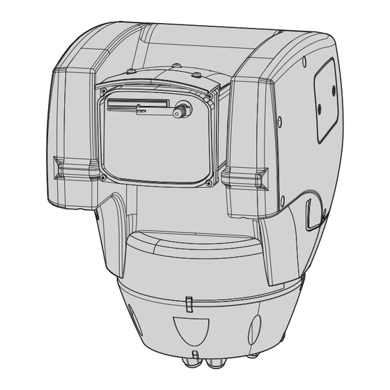
7.5 Fixing the upper body 7.6 Hardware configuration Point the self-centering connector (01) of the upper 7.6.1 Opening the configuration door unit. Point the side set (02) so that it faces the frontal Before powering the device it must be configured vision of the camera. -
Page 21: Configuration Of The Dip-Switches
8 Switching on 7.6.2 Configuration of the dip-switches When the dip-switch rocker (SW) is up it The automatic pre-heating (De-Ice) process represents the value 1 (ON) while if it is could be started whenever the device is down it represents the value 0 (OFF). switched on and the ambient temperature is below 0°C (+32°F). -
Page 22: Configuration
Set the IP address of the PC: 192.168.10.1 (or 192.168.10.2, etc.). The product can work via ONVIF or TCAM (VIDEOTEC) protocol. In the event the Connect the unit to the LAN network, provide power ONVIF protocol is used, make sure to set the... -
Page 23: Installing The Software
9.1.3 Installing the software Assign a name to the camera and to the unit. Select the ONVIF or TCAM protocol and set the device's Insert the CD and start the autoplay or launch the IP address and the access credentials. Select the installer. - Page 24 To display the cameras on different computers, install Once the server has been added it must be registered the TVMS client and use it to connect to the TVMS to display it. Drag the server icon on the right column server in remote.
-
Page 25: Web Interface
9.2 Web interface 9.2.2 User Controls page To control the device through the browser, select the During the first connection assign an User Control entry. A new window will open with a address other than 192.168.10.100. virtual keyboard to enter commands. Browsers supported: Microsoft Internet Explorer, Microsoft Edge, Google Chrome, Mozilla Firefox. -
Page 26: Device Parameters Page
9.2.3 Device Parameters Page • Focus Near/Focus Far In the Device Settings menu, it is possible to view the information on the product code, the serial number, the MAC address, the firmware version and the hardware review. Fig. 33 • Wiper/Washer: If a tank was installed and configured, the command activates the wiper and the wash procedure. -
Page 27: Network Configuration Page
9.2.5 Network Configuration page NTP Server: It is also possible to specify if the device needs to be synchronised with an external NTP From menu entry Network Configuration it is possible (Network Time Protocol) server. to change the setting of the device. It is possible •... -
Page 28: Movement Parameters Page
9.2.7 Movement Parameters page • Tilt Limits: Enables the limits of Tilt. • Tilt Start: Sets the start limit of Tilt. From menu entry Movement Parameters it is possible to control, via web, all Pan & Tilt parameters. • Tilt End: Sets the end limit of Tilt. •... -
Page 29: Patrol Page
9.2.7.2 Patrol Page 9.2.8 Preset Parameters page From menu entry Patrol it is possible to specify the From menu entry Preset Parameters a number of preset patrol start and end. Patrol is a function that parameters relative to the presets can be configured: moves the unit between two or more presets. -
Page 30: Digital I/O Page
9.2.10 Digital I/O Page 9.2.11 Wiper From menu entry Digital I/O it is possible to configure Do not use the wiper if the outside the digital channels available in the device. What temperature is below 0°C or in case of ice. follows is a brief description of the configurable parameters for each digital input. -
Page 31: Encoder Parameters Page
9.2.13 Encoder Parameters page 9.2.14 Camera Settings page In the Encoder Settings menu, it is possible to The camera integrated in the device can be configure up to 4 video flows of the device. The first configured under the Camera Parameters menu: flow must be compressed with the algorithm H.264/ •... -
Page 32: Directional Osd Page
9.2.15 Directional OSD Page • Other: It allows setting other values: Image Mirror, Noise Reduction, Wide Dynamic (Visibility The device supports definition of four pan regions Enhancer), High Resolution, Aperture Control, and information text video display based on the Defog, Highlight Correction. position of the Pan &... -
Page 33: Video Analysis Page
9.2.17 Tools Page Start From menu entry Tools it is possible to re-set the predefined values for the entire configuration of 0° device or only for a number of specific sections. This section: • Update the firmware of the device. •... -
Page 34: Accessories
10 Accessories 10.3 Parapet bracket Parapet bracket with internal cable channel. For further details on configuration and use, refer to the relative manual. 10.1 Washer The P&T can be equipped with an external pump that supplies water for the glass to be cleaned. Fig. -
Page 35: Instructions For Normal Operation
11 Instructions for normal 11.1 Special controls operation SPECIAL CONTROLS Action Command Do not use the wiper if the outside Protocol temperature is below 0°C or in case of ice. TCAM ONVIF (auxiliary command) If it is left on, the wiper automatically Wiper Start Save Preset 85 tt:Wiper|On... -
Page 36: Maintenance
& tilt. The operation can also be done in remote mode (only Avoid ethyl alcohol, solvents, hydrogenated VIDEOTEC MACRO and PELCO D protocols) using an hydrocarbide, strong acid and alkali. Such USB/485 Serial converter (not supplied). -
Page 37: Information On Disposal And Recycling
14 Information on disposal 15 Troubleshooting and recycling Contact an authorized support centre if the problems listed below persist or you have The European Directive 2012/19/EU on Waste any other issues that are not described Electrical and Electronic Equipment (WEEE) mandates here. -
Page 38: Technical Data
16 Technical data 16.3 Electrical Supply voltage/Current consumption: CAUTION! TNV-1 installation type. The • 230Vac, 0.4A, 50/60Hz installation is type TNV-1, do not connect it to SELV circuits. • 120Vac, 0.8A, 50/60Hz • 24Vac, 4A, 50/60Hz CAUTION! In order to reduce the risk of fire, Power consumption: only use UL Listed or CSA certified cables •... -
Page 39: Video
16.5 Video Minimum Illumination, B/W (ICR-ON): • 0.05lx, 1/30s, 50 IRE (Normal mode) Video encoder • 0.013lx, 1/30s, 50 IRE (High sensitivity mode) • Communication protocol: ONVIF, Profile S • 0.002lx, 1/3s, 30 IRE (High sensitivity mode) • Device configuration: TCP/IPv4-IPv6, UDP/IPv4- Lens: f=4.3 mm (wide) ~ 129.0 mm (tele), from F1.6 IPv6, HTTP, HTTPS, NTP, DHCP, WSDISCOVERY, QoS, to F4.7... -
Page 40: Illuminators
16.8 Illuminators 16.10 Certifications Electrical safety (CE): EN60950-1, IEC60950-1 LED illuminator Electromagnetic compatibility (CE): EN610000-6-4, Horizontal beam: 10° or 30° EN50130-4, EN55022 (Class A), FCC Part 15 (Class A) Wavelength: 850nm, 940nm, white light Outdoor installation (CE): EN60950-22, IEC60950-22 Auto power on through integrated sensor or by VMS Photobiological safety (CE): EN62471 The camera and the light beam are factory aligned IP protection degree: EN60529 (IP66) -
Page 41: Technical Drawings
17 Technical drawings The dimensions of the drawings are in millimetres. Fig. 62 ULISSE COMPACT HD. MNVCUCHD_1801_EN... - Page 42 Fig. 63 ULISSE COMPACT HD with LED illuminator. MNVCUCHD_1801_EN...
- Page 43 MNVCUCHD_1801_EN...
- Page 44 Email: info@videotec.com Tel. +33 1 60491816 - Fax +33 1 69284736 Email: info.fr@videotec.com Asia Pacific Videotec (HK) Ltd Americas Videotec Security, Inc. Flat 8, 19/F. On Dak Industrial Building, No. 2-6 Wah Sing Street Gateway Industrial Park, 35 Gateway Drive, Suite 100 Kwai Chung, New Territories - Hong Kong Plattsburgh, NY 12901 - U.S.A.
- Page 45 ITALIANO ULISSE COMPACT HD Telecamera PTZ da esterni per dettagliate immagini Full HD e alte prestazioni Italiano - Manuale di istruzioni...
- Page 47 Sommario I T A L I A N O 1 Informazioni sul presente manuale ................7 1.1 Convenzioni tipografiche ............................. 7 2 Note sul copyright e informazioni sui marchi commerciali ........7 3 Norme di sicurezza ......................7 4 Identificazione ......................10 4.1 Descrizione e designazione del prodotto .....................10 4.2 Marcatura del prodotto ............................10 4.2.1 Controllo della marcatura ..............................10...
- Page 48 9.1.2 Procedura di configurazione tramite software ......................20 9.1.3 Installazione del software ..............................21 9.2 Interfaccia web ...............................23 9.2.1 Pagina Home ...................................23 9.2.2 Pagina Controlli Utente ...............................23 9.2.3 Pagina Parametri Dispositivo ............................24 9.2.4 Pagina Statistiche Dispositivo ............................24 9.2.5 Pagina Configurazione Rete ..............................25 9.2.6 Pagina Configurazione Utenti ............................25 9.2.7 Pagina Parametri Movimento ............................26 9.2.7.1 Pagina Autopan ......................................26...
- Page 49 16.7 Telecamere ................................37 16.8 Illuminatori ................................38 16.9 Ambiente ................................38 16.10 Certificazioni ...............................38 17 Disegni tecnici ......................39 MNVCUCHD_1801_IT...
- Page 50 MNVCUCHD_1801_IT...
-
Page 51: Informazioni Sul Presente Manuale
1 Informazioni sul presente 3 Norme di sicurezza manuale ATTENZIONE! L’impianto elettrico al quale è collegata l’unità deve essere dotato di Prima di installare e utilizzare questa unità, leggere un interruttore di protezione bipolare attentamente tutta la documentazione fornita. Tenere automatico da 20A max. - Page 52 • La categoria di installazione (detta anche categoria ATTENZIONE! L'installazione e la di sovratensione) specifica i livelli della tensione manutenzione del dispositivo deve transitoria di rete alla quale l’apparato è soggetto. essere eseguita solo da personale tecnico La categoria dipende dal luogo di installazione specializzato.
- Page 53 • Collegare il dispositivo ad una sorgente • La manutenzione del dispositivo deve essere d’alimentazione corrispondente a quella indicata eseguita solo da personale qualificato. Durante le nell’etichetta di marcatura. Prima di procedere operazioni di manutenzione l'operatore è esposto con l’installazione verificare che la linea elettrica al rischio di folgorazione o ad altri pericoli.
-
Page 54: Identificazione
Sui brandeggi è applicata una etichetta conforme alla marcatura CE. del prodotto ULISSE COMPACT HD è una telecamera PTZ Full HD di rete, IP66, che fornisce immagini di ottima qualità ad alta definizione. La telecamera Full HD integra uno zoom ottico 30x ed è... -
Page 55: Versioni
5 Versioni 5.2 Illuminatore a LED Il brandeggio può essere provvisto di un illuminatore 5.1 Tergicristallo integrato a LED. Il prodotto può essere provvisto di tergicristallo. Fig. 4 Fig. 3 Per ulteriori informazioni fare riferimento Per ulteriori informazioni fare riferimento al relativo capitolo (9.2.2 Pagina Controlli al relativo capitolo (9.2.2 Pagina Controlli Utente, pagina 23). -
Page 56: Preparazione Del Prodotto Per L'utilizzo
6 Preparazione del prodotto 6.2 Disimballaggio per l'utilizzo Alla consegna del prodotto verificare che l'imballo sia integro e non presenti segni evidenti di cadute o abrasioni. Qualsiasi intervento non espressamente approvato dal costruttore fa decadere la In caso di danni evidenti all'imballo contattare garanzia. -
Page 57: Lavoro Preparatorio Prima Dell'installazione
6.5 Lavoro preparatorio prima 7 Installazione dell’installazione Non effettuare per nessun motivo alterazioni o collegamenti non previsti 6.5.1 Fissaggio del supporto in questo manuale. Il mancato rispetto Sono disponibili diversi tipi di supporto (10 delle indicazioni fornite nel manuale in Accessori, pagina 32). -
Page 58: Fissaggio Della Base Al Supporto
7.2 Fissaggio della base al 7.3 Collegamento della scheda supporto connettori 7.3.1 Descrizione della scheda Utilizzare le viti e le rondelle fornite con la connettori base. Dopo aver posizionato la guarnizione (01), fissare la DESCRIZIONE DELLA SCHEDA base (02) sul supporto (03) utilizzando le viti (04), le Connettore Funzione rondelle dentellate e rondelle piane (05). -
Page 59: Collegamento Della Linea Di Alimentazione
7.3.2 Collegamento della linea di Collegare i cavi di alimentazione al morsetto J2 come descritto in tabella. alimentazione COLLEGAMENTO DELLA LINEA DI ALIMENTAZIONE Eseguire le connessioni elettriche in Colore Morsetti assenza di alimentazione e con dispositivo Alimentazione 24Vac di sezionamento aperto. Definito dall'installatore N (Neutro) All’atto dell’installazione controllare che... -
Page 60: Collegamento Della Scheda Connettori Secondaria
7.4 Collegamento della scheda 7.4.2 Collegamento degli ingressi di allarme connettori secondaria Tutti i cavi di segnale devono essere Tutti i cavi di segnale devono essere raggruppati con una fascetta. raggruppati con una fascetta. Nel caso di allarme a contatto pulito eseguire il 7.4.1 Descrizione della scheda collegamento come illustrato in figura. -
Page 61: Collegamento Dei Relè
7.4.3 Collegamento dei relè 7.4.4 Collegamento dell'impianto di lavaggio Il relè è utilizzabile con le specifiche descritte di seguito. Tensione di lavoro: Per ulteriori dettagli sulla configurazione fino a 30Vac oppure 60Vdc. Corrente: 1A e l’utilizzo fare riferimento al manuale del max. -
Page 62: Fissaggio Del Corpo Superiore
7.5 Fissaggio del corpo superiore 7.6 Configurazione hardware Orientare il connettore autocentrante (01) dell'unità 7.6.1 Apertura dello sportellino di superiore. Orientare la sporgenza laterale (02) nel configurazione senso di visione frontale della telecamera. Posizionare Prima di alimentare il dispositivo, è necessario l'unità... -
Page 63: Configurazione Dei Dip-Switch
8 Accensione 7.6.2 Configurazione dei dip-switch La levetta del dip-switch (SW) verso l'alto La procedura di preriscaldamento rappresenta il valore 1 (ON) mentre la automatico (De-Ice) si potrebbe attivare levetta verso il basso rappresenta il valore tutte le volte che il dispositivo viene acceso 0 (OFF). -
Page 64: Configurazione
Configurare l’indirizzo IP del PC: 192.168.10.1 (oppure 192.168.10.2, ecc.). Il prodotto può funzionare mediante protocollo ONVIF o TCAM (VIDEOTEC). Se Collegare l'unità alla rete LAN, fornire alimentazione si utilizza il protocollo ONVIF, assicurarsi e avviare il browser Microsoft Internet Explorer® 6.0 o di impostare l'ora correttamente nel superiore. - Page 65 9.1.3 Installazione del software Assegnare un nome alla telecamera ed al gruppo. Selezionare il protocollo ONVIF o TCAM e impostare Inserire il CD ed avviare l'autoplay o lanciare l'indirizzo IP del dispositivo e le credenziali di accesso. l'installer. Si aprirà una pagina web che permetterà Selezionare i profili di streaming ed assicurarsi che la l'installazione delll'applicazione TVMS server (32 o 64 voce Use PTZ sia abilitata.
- Page 66 Per visualizzare le telecamere su più computer è Dopo aver aggiunto il server sarà necessario necessario installare il TVMS client ed utilizzarlo per registrarlo per la visualizzazione. Trascinare l'icona del collegarsi in remoto al TVMS server. Per configurare il server sulla colonna di destra come illustrato in figura. client, accedere con le credenziali di default.
-
Page 67: Pagina Home
9.2 Interfaccia web 9.2.2 Pagina Controlli Utente Per controllare il dispositivo via browser, selezionare Alla prima connessione assegnare un la voce Controlli Utente. Si aprirà una nuova finestra indirizzo diverso da 192.168.10.100. con una tastiera virtuale per inviare i comandi. Browser supportati: Microsoft Internet Explorer, Microsoft Edge, Google Chrome, Mozilla Firefox. -
Page 68: Pagina Parametri Dispositivo
9.2.3 Pagina Parametri Dispositivo • Focus Near/Focus Far Alla voce del menu Parametri Dispositivo è possibile visualizzare le informazioni sul codice prodotto, il numero di serie, l'indirizzo MAC, la versione dei firmware e la revisione dell'hardware. Fig. 33 • Wiper/Washer: Se è stata installata e configurata una tanica, il comando aziona il tergicristallo e la procedura di lavaggio. -
Page 69: Pagina Configurazione Rete
9.2.5 Pagina Configurazione Rete Server NTP: È possibile inoltre specificare se il dispositivo debba sincronizzarsi con un server NTP Alla voce del menu Configurazione Rete è possibile (Network Time Protocol) esterno. cambiare l'impostazione di rete del dispositivo. È • DISABILITATO: Selezionare questa opzione se non possibile decidere se il dispositivo debba avere un si desidera sincronizzare data e ora del dispositivo. -
Page 70: Pagina Parametri Movimento
9.2.7 Pagina Parametri Movimento • Limiti Tilt: Abilita i limiti del Tilt. • Tilt Inizio: Imposta il limite iniziale del Tilt. Alla voce del menu Parametri Movimento è possibile controllare via web tutti i parametri del brandeggio. • Tilt Fine: Imposta il limite finale del Tilt. •... -
Page 71: Pagina Patrol
9.2.7.2 Pagina Patrol 9.2.8 Pagina Parametri Preset Alla voce del menu Patrol è possibile specificare Alla voce del menu Parametri Preset sono il preset di inizio e di fine del patrol. Patrol è una configurabili alcuni parametri relativi ai preset: funzione che fa muovere l'unità... -
Page 72: Pagina I/O Digitali
9.2.10 Pagina I/O Digitali 9.2.11 Wiper Alla voce del menu I/O Digitali è possibile configurare Non utilizzare il tergicristallo se la i canali digitali presenti nel dispositivo. Segue una temperatura esterna è inferiore a 0°C o in breve descrizione dei parametri configurabili per presenza di ghiaccio. -
Page 73: Pagina Parametri Encoder
9.2.13 Pagina Parametri Encoder 9.2.14 Pagina Parametri Telecamera Alla voce del menù Parametri Encoder è possibile Alla voce del menu Parametri Camera è possibile configurare fino a 4 flussi video del dispositivo. Il configurare la telecamera integrata nel dispositivo: primo flusso è obbligatoriamente compresso con •... -
Page 74: Pagina Osd Direzionale
9.2.15 Pagina OSD Direzionale • Altro: Permette di impostare altri valori: Immagine Speculare, Riduzione Rumore, Wide Dynamic Il dispositivo supporta la definizione di quattro (Visibility Enhancer), Alta Risoluzione, Controllo regioni pan e la visualizzazione a video di testo Apertura, Defog, Correzione Sovraesposizione. informativo in base alla posizione del brandeggio. -
Page 75: Pagina Analisi Video
9.2.17 Pagina Strumenti Start Alla voce del menu Strumenti è possibile reimpostare i valori predefiniti per tutta la configurazione del 0° dispositivo o solo per alcune sezioni specifiche. In questa sezione è inoltre possibile: • Aggiornare il firmware del dispositivo. •... -
Page 76: Accessori
10 Accessori 10.3 Supporto da parapetto Supporto per montaggio a parapetto con passaggio Per ulteriori dettagli sulla configurazione interno cavi. e l’utilizzo fare riferimento al manuale del relativo accessorio. 10.1 Impianto di lavaggio Il brandeggio può essere dotato di una pompa esterna che fornisce acqua per la pulizia del vetro. -
Page 77: Istruzioni Di Funzionamento Ordinario
11 Istruzioni di 11.1 Comandi speciali funzionamento ordinario COMANDI SPECIALI Azione Comando Non utilizzare il tergicristallo se la Protocollo temperatura esterna è inferiore a 0°C o in TCAM ONVIF (auxiliary presenza di ghiaccio. command) Wiper Start Salvare Preset 85 tt:Wiper|On Il tergicristallo si disattiva in modo automatico se lasciato acceso. -
Page 78: Manutenzione
L’operazione può inoltre essere effettuata da remoto (solo protocolli VIDEOTEC Si consiglia di utilizzare un panno morbido con MACRO e PELCO D) con convertitore USB/Seriale 485 sapone neutro diluito con acqua o prodotti specifici (non fornito in dotazione). -
Page 79: Informazioni Sullo Smaltimento E Il Riciclo
14 Informazioni sullo 15 Risoluzione dei problemi smaltimento e il riciclo Per qualunque problematica non descritta o se i problemi elencati in seguito La Direttiva Europea 2012/19/UE sui Rifiuti di dovessero persistere, contattare il centro di Apparecchiature Elettriche ed Elettroniche (RAEE) assistenza autorizzato. -
Page 80: Dati Tecnici
16 Dati tecnici 16.3 Elettrico Tensione di alimentazione/Corrente assorbita: ATTENZIONE! L'installazione è di tipo TNV-1. • 230Vac, 0.4A, 50/60Hz Non collegare a circuiti SELV. • 120Vac, 0.8A, 50/60Hz ATTENZIONE! Per ridurre il rischio di • 24Vac, 4A, 50/60Hz incendio usare solamente cavi certificati Potenza assorbita: UL Listed o CSA aventi sezioni maggiori o •... -
Page 81: Video
16.5 Video Illuminazione Minima, B/W (ICR-ON): • 0.05lx, 1/30s, 50 IRE (modalità Normale) Encoder video • 0.013lx, 1/30s, 50 IRE (modalità Alta Sensibilità) • Protocollo di comunicazione: ONVIF, Profilo S • 0.002lx, 1/3s, 30 IRE (modalità Alta Sensibilità) • Configurazione del dispositivo: TCP/IPv4- Ottica: f=4.3 mm (wide) ~ 129.0 mm (tele), da F1.6 IPv6, UDP/IPv4-IPv6, HTTP, HTTPS, NTP, DHCP, fino a F4.7... - Page 82 16.8 Illuminatori 16.10 Certificazioni Sicurezza elettrica (CE): EN60950-1, IEC60950-1 Illuminatore a LED Compatibilità elettromagnetica (CE): EN610000-6-4, Fascio orizzontale: 10° oppure 30° EN50130-4, EN55022 (Classe A), FCC Part 15 (Classe A) Lunghezza d’onda: 850nm, 940nm, luce bianca Installazione all'esterno (CE): EN60950-22, IEC60950- Accensione automatica mediante sensore integrato o da VMS Sicurezza fotobiologica (CE): EN62471...
- Page 83 17 Disegni tecnici Le dimensioni dei disegni sono espresse in millimetri. Fig. 62 ULISSE COMPACT HD. MNVCUCHD_1801_IT...
- Page 84 Fig. 63 ULISSE COMPACT HD con illuminatore a LED. MNVCUCHD_1801_IT...
- Page 85 MNVCUCHD_1801_IT...
- Page 86 Email: info@videotec.com Tel. +33 1 60491816 - Fax +33 1 69284736 Email: info.fr@videotec.com Asia Pacific Videotec (HK) Ltd Americas Videotec Security, Inc. Flat 8, 19/F. On Dak Industrial Building, No. 2-6 Wah Sing Street Gateway Industrial Park, 35 Gateway Drive, Suite 100 Kwai Chung, New Territories - Hong Kong Plattsburgh, NY 12901 - U.S.A.
- Page 87 FRANÇAIS ULISSE COMPACT HD Caméra PTZ extérieure pour images détaillées en Full HD et hautes performances Français - Manuel d’instructions...
- Page 89 Sommaire F R A N Ç A I S 1 À propos de ce mode d’emploi ..................7 1.1 Conventions typographiques ..........................7 2 Notes sur le copyright et informations sur les marques de commerce ..... 7 3 Normes de securité ......................7 4 Identification ........................
- Page 90 9.1.2 Procédure de configuration par l'intermédiaire du logiciel ...................20 9.1.3 Installation du logiciel ................................21 9.2 Interface web ................................23 9.2.1 Page Home ....................................23 9.2.2 Page Contrôles Utilisateur ..............................23 9.2.3 Page Paramètres Dispositif ..............................24 9.2.4 Page Statistiques Dispositif ..............................24 9.2.5 Page Configuration Réseau ..............................25 9.2.6 Page Configuration Utilisateurs ............................25 9.2.7 Page Paramètres Mouvement ............................26 9.2.7.1 Page Autopan.......................................26...
- Page 91 16.7 Caméras ..................................37 16.8 Projecteurs ................................38 16.9 Environnement ..............................38 16.10 Certifications ..............................38 17 Dessins techniques ....................39 MNVCUCHD_1801_FR...
- Page 92 MNVCUCHD_1801_FR...
-
Page 93: À Propos De Ce Mode D'emploi
1 À propos de ce mode 3 Normes de securité d’emploi ATTENTION! Le circuit électrique auquel l'unité est reliée doit être équipé d'un Avant d'installer et d'utiliser cette unité, lire interrupteur de protection bipolaire attentivement toute la documentation fournie. automatique de 20A max. Cet interrupteur Garder le manuel à... - Page 94 • La catégorie d’installation (ou catégorie de ATTENTION! L’installation et l’entretien surtension) spécifie les niveaux de la tension de du dispositif doivent être effectués secteur correspondant à l’appareil. La catégorie exclusivement par un personnel technique dépend du lieu d’installation et du dispositif qualifié.
- Page 95 • Raccorder le système à une source d'alimentation • L'entretien du dispositif doit uniquement être conforme à celle figurant sur l'étiquette de effectué par un personnel qualifié. Durant les marquage du produit. Avant de procéder à opérations d'entretien, l'opérateur est exposé au l'installation, vérifier que la ligne électrique est risque d'électrocution ou autres.
-
Page 96: Identification
Les tourelles portent un étiquette conforme au marquage CE. produit ULISSE COMPACT HD est une caméra PTZ réseau FullHD IP66 qui offre une excellente qualité en haute défnition des images. La caméra Full HD intègre un zoom optique 30x et est en mesure d'identifer avec précision des détails... -
Page 97: Versions
5 Versions 5.2 Projecteur à LED La tourelle peut être équipée d’un projecteur à LED. 5.1 Essuie-glace intégré Le produit peut être équipé d’un essuie-glace. Fig. 4 Fig. 3 Pour d'autres renseignements se référer à le chapitre relatif (9.2.2 Page Contrôles Pour d'autres renseignements se référer Utilisateur, page 23). -
Page 98: Préparation Du Produit En Vue De L'utilisation
6 Préparation du produit en 6.2 Déballage vue de l’utilisation Lors de la livraison du produit, vérifier que l’emballage est en bon état et l’absence de tout signe évident de chute ou d’abrasion. Toute modification non approuvée expressément par le fabricant entraînera En cas de dommages évidents, contacter l’annulation de la garantie. -
Page 99: Opérations À Effectuer Avant L'installation
6.5 Opérations à effectuer avant 7 Installation l’installation Ne procéder sous aucun prétexte à des modifications ou des connexions non 6.5.1 Fixation du support prévues dans ce manuel. L’utilisation Plusieurs types de supports sont disponibles (10 d’appareils inadéquats peut comporter Accessoires, page 32). -
Page 100: Fixage De La Base Au Support
7.2 Fixage de la base au support 7.3 Connexion de la carte de connexion Utiliser les vis et les rondelles fournies avec la base. 7.3.1 Description de la carte de connexion Après avoir installé la garniture (01), fixer la base (02) sur son support (03) au moyen des vis (04), des DESCRIPTION DE LA CARTE rondelles dentées et des rondelles plates (05). -
Page 101: Connexion De La Ligne D'alimentation
7.3.2 Connexion de la ligne Connecter les câbles d'alimentation au borne J2 comme décrit dans le tableau. d'alimentation CONNEXION DE LA LIGNE D'ALIMENTATION Il faut effectuer les connexions électriques Couleur Bornes en absence d'alimentation et lorsque le Alimentation 24Vac dispositif de sectionnement ouvert. Défini par l'installateur N (Neutre) Contrôler que les sources d'alimentation et... -
Page 102: Connexion De La Carte Secondaire Des Connecteurs
7.4 Connexion de la carte 7.4.2 Connexion des entrées de l'alarme secondaire des connecteurs Tous les câbles de signalisation doivent également être regroupés avec un collier. Tous les câbles de signalisation doivent Dans le cas d'une alarme à contact propre, effectuer également être regroupés avec un collier. -
Page 103: Branchement Des Relais
7.4.3 Branchement des relais 7.4.4 Branchement du système de lavage Le relais est utilisable avec les spécifications décrites ci-après. Tension de travail: jusqu'à Pour de plus amples informations sur la 30Vac ou 60Vdc. Courant: 1A max. Utiliser configuration et l'utilisation, consulter le des câbles d'une section adéquate avec manuel de l'accessoire correspondant. -
Page 104: Fixation Du Corps Supérieur
7.5 Fixation du corps supérieur 7.6 Configuration du matériel Orienter le connecteur autocentrant (01) de l’unité 7.6.1 Ouverture du volet de supérieure. Orienter la saillie latérale (02) dans le sens configuration de vision frontale de la caméra. Positionner l’unité Avant de mettre l'appareil sous tension, il est supérieure sur la base selon l’orientation représentée nécessaire de le configurer correctement au moyen sur la figure. -
Page 105: Configuration Des Dip-Switch
8 Allumage 7.6.2 Configuration des dip-switch Le levier du dip-switch (SW) vers le haut La procédure de préchauffage automatique représente la valeur 1 (ON) tandis que le (De-Ice) peut être activée chaque fois levier vers le bas représente la valeur 0 que le dispositif est mis en fonction à... -
Page 106: Configuration
Fig. 21 partir d’un PC. Le produit peut fonctionner par protocole Configurer l’adresse IP du PC: 192.168.10.1 (ou ONVIF ou TCAM (VIDEOTEC). En cas 192.168.10.2, etc.). d'utilisation du protocole ONVIF, s'assurer Connecter l'unité au réseau LAN, mettre sous tension de paramétrer correctement l'heure du et lancer Microsoft Internet Explorer®... -
Page 107: Installation Du Logiciel
9.1.3 Installation du logiciel Attribuer un nom à la caméra et au groupe. Sélectionner le protocole ONVIF ou TCAM et Insérer le CD et démarrer l'autoplay ou lancer configurer l'adresse IP du dispositif et les données l'installer. Une page web s'ouvrira pour permettre d'accès. - Page 108 Pour afficher les caméras sur plusieurs ordinateurs Après avoir ajouté le serveur, il sera nécessaire de le il faut installer le TVMS client et l'utiliser pour régler pour l'affichage. Faire glisser l'icône du serveur se connecter à distance au serveur TVMS. Pour sur la colonne de droite, comme illustré...
-
Page 109: Page Home
9.2 Interface web 9.2.2 Page Contrôles Utilisateur Pour contrôler la dispositif par browser, sélectionner À la première connexion, donner une la mention Contrôle Utilisateur. Une nouvelle fenêtre adresse différente de 192.168.10.100. s'ouvrira, avec un clavier virtuel pour sélectionner les commandes. Logiciels de navigation supportés: Microsoft Internet Explorer, Microsoft Edge, Google Chrome, Mozilla Firefox. -
Page 110: Page Paramètres Dispositif
9.2.3 Page Paramètres Dispositif • Focus Near/Focus Far À la rubrique du menu Paramètres Dispositif, on peut afficher les informations sur le code produit, le numéro de série, l'adresse MAC, la version des firmwares et la révision du matériel informatique. Fig. -
Page 111: Page Configuration Réseau
9.2.5 Page Configuration Réseau Serveur NTP: Il est également possible de mentionner si le dispositif doit se synchroniser avec A la mention du menu Configuration Réseau il est un serveur NTP (Network Time Protocol) externe. possible de changer la configuration de réseau de •... -
Page 112: Page Paramètres Mouvement
9.2.7 Page Paramètres Mouvement • Limites Tilt: Configure la limite initiale de Tilt. • Tilt Début: Configure la limite initiale de Tilt. A la mention du menu Paramètres Mouvement il est possible de contrôler par web tous les paramètres de •... -
Page 113: Page Patrol
9.2.7.2 Page Patrol 9.2.8 Page Paramètres Preset A la mention du menu Patrol il est possible d'indiquer A la mention du menu Paramètres Preset on peut le preset de début et de fin du patrol. Patrol est une configurer certains paramètres concernant les preset: fonction qui déplace l'unité... -
Page 114: Page I/O Digitaux
9.2.10 Page I/O Digitaux 9.2.11 Wiper Dans la carte I/O Digitaux il est possible de configurer Ne pas utiliser l’essuie-glace avec les canaux digitaux présents dans le dispositif. Il y a température extérieure inférieure à 0°C ou ci-dessous une courte description des paramètres en cas de givre. -
Page 115: Page Paramètres Encoder
9.2.13 Page Paramètres Encoder 9.2.14 Page Paramètres Caméra À la rubrique du menu Paramètres Encodeur, il Dans le menu Paramètres Caméra il est possible de est possible de configurer jusqu'à 4 flux vidéo configurer la caméra intégrée au dispositif: du dispositif. Le premier flux est obligatoirement •... -
Page 116: Page Osd Directionnelle
9.2.15 Page OSD Directionnelle • Autre: Cela permet d'installer d'autres valeurs: Image Renversée, Noise Reduction, Wide Dynamic Le dispositif supporte la définition de quatre régions (Visibility Enhancer), Haute Resolution, Contrôle De de rotation (pan) et l'affichage vidéo d'un texte L'ouverture, Defog, Correction De La Surexposition. d'information en fonction de la position de la tourelle. -
Page 117: Page Analyses Vidéo
9.2.17 Page Instruments Start A la mention du menu Instruments il est possible de reconfigurer les valeurs prédéfinies pour toute 0° la configuration de la tourelle ou seulement pour certaines sections spécifiques. Dans cette section, il est en outre possible : •... -
Page 118: Accessoires
10 Accessoires 10.3 Support fixation sol Support de fixation au sol avec passage interne des Pour de plus amples informations sur la câbles. configuration et l'utilisation, consulter le manuel de l'accessoire correspondant. 10.1 Système de lavage La tourelle peut être équipée d'une pompe extérieure qui fournit de l'eau pour le nettoyage de la vitre. -
Page 119: Instructions De Fonctionnement Courant
11 Instructions de 11.1 Commandes spéciales fonctionnement courant COMMANDES SPÉCIALES Action Commande Ne pas utiliser l’essuie-glace avec Protocole température extérieure inférieure à 0°C ou TCAM ONVIF (auxiliary en cas de givre. command) Wiper Start Sauver Preset 85 tt:Wiper|On L’essuie-glace est exclu de façon automatique si on le laisse allumé. -
Page 120: Entretien
être effectuée sur place au moyen du câble fourni hydrocarbures hydro-génés, acides forts avec la tourelle. L’opération peut etre effectuè à et alcali. L’emploi de ce type de produits distance (seulement MACRO/VIDEOTEC et PELCO abîme d’une façon irréparable la surface D protocoles) avec un convertisseur USB/Sériel 485 traitée. -
Page 121: Informations Sur L'élimination Et Le Recyclage
14 Informations sur 15 Dépannage l'élimination et le recyclage Pour toute problématique que ce soit non décrite ou si les problèmes énumérés La Directive Européenne 2012/19/UE sur les déchets ci-après persistent, contacter le centre d'équipements électriques et électroniques (DEEE) d'assistance autorisé. exige que ces dispositifs ne doivent pas être éliminés dans le flux normal de déchets solides municipaux, mais ils doivent être collectés séparément afin... -
Page 122: Données Techniques
16 Données techniques 16.3 Électrique Tension d’alimentation/Courant absorbé: ATTENTION! L'installation est du type TNV- • 230Vac, 0.4A, 50/60Hz 1. Ne pas la connecter à des circuits SELV. • 120Vac, 0.8A, 50/60Hz ATTENTION! Pour réduire les risques • 24Vac, 4A, 50/60Hz d’incendie, utiliser uniquement des câbles Puissance absorbée: certifiés UL Listed ou CSA de sections égales... -
Page 123: Vidéo
16.5 Vidéo Éclairage minimum, B/W (ICR-ON): • 0.05lx, 1/30s, 50 IRE (mode Normal) Encodeur vidéo • 0.013lx, 1/30s, 50 IRE (Haute sensibilité) • Protocole de communication: ONVIF, Profil S • 0.002lx, 1/3s, 30 IRE (Haute sensibilité) • Configuration du dispositif: TCP/IPv4-IPv6, UDP/ Objectif: f=4.3 mm (wide) ~ 129.0 mm (tele), de F1.6 IPv4-IPv6, HTTP, HTTPS, NTP, DHCP, WSDISCOVERY, à... -
Page 124: Projecteurs
16.8 Projecteurs 16.10 Certifications Sécurité électrique (CE): EN60950-1, IEC60950-1 Projecteur à LED Compatibilité électromagnétique (CE): EN610000-6-4, Angle horizontal: 10° ou 30° EN50130-4, EN55022 (Classe A), FCC Part 15 (Classe A) Longueur d'onde: 850nm, 940nm, lumière blanche Installation à l'extérieur (CE): EN60950-22, IEC60950- Éclairage automatique graçe au senseur integré... -
Page 125: Dessins Techniques
17 Dessins techniques Les dimensions des dessins sont exprimées en millimètres. Fig. 62 ULISSE COMPACT HD. MNVCUCHD_1801_FR... - Page 126 Fig. 63 ULISSE COMPACT HD avec projecteur à LED. MNVCUCHD_1801_FR...
- Page 127 MNVCUCHD_1801_FR...
- Page 128 Email: info@videotec.com Tel. +33 1 60491816 - Fax +33 1 69284736 Email: info.fr@videotec.com Asia Pacific Videotec (HK) Ltd Americas Videotec Security, Inc. Flat 8, 19/F. On Dak Industrial Building, No. 2-6 Wah Sing Street Gateway Industrial Park, 35 Gateway Drive, Suite 100 Kwai Chung, New Territories - Hong Kong Plattsburgh, NY 12901 - U.S.A.
- Page 129 DEUTSCH ULISSE COMPACT HD PTZ Kamera für den Außenbereich für detaillierte Full HD-Bilder und High-Performance Deutsch - Bedienungsanleitung...
- Page 131 Inhaltsverzeichnis D E U T S C H 1 Allgemeines ........................7 1.1 Schreibweisen ................................7 2 Anmerkungen zum Copyright und Informationen zu den Handelsmarken ..... 7 3 Sicherheitsnormen ......................7 4 Identifizierung ......................10 4.1 Beschreibung und Bezeichnung des Produktes ..................10 4.2 Kennzeichnung des Produkts..........................10 4.2.1 Prüfung der Kennzeichnung .............................10 5 Versionen........................
- Page 132 9.1.2 Konfigurationsvorgang über Software ..........................20 9.1.3 Installation der Software ..............................21 9.2 Web-Schnittstelle ..............................23 9.2.1 Home Seite ....................................23 9.2.2 Benutzersteuerung Seite ..............................23 9.2.3 Geräteparameter Seite ................................24 9.2.4 Gerätestatistiken Seite .................................24 9.2.5 Netzwerk-Konfiguration Seite ............................25 9.2.6 Benutzer-Konfiguration Seite ............................25 9.2.7 Bewegungsparameter Seite ..............................26 9.2.7.1 Autopan Seite.......................................26 9.2.7.2 Patrol Seite ........................................27 9.2.7.3 Bewegungsanforderung Seite ................................27...
- Page 133 16.7 Kameras ..................................37 16.8 Scheinwerfer .................................38 16.9 Umgebung ................................38 16.10 Zertifizierungen ..............................38 17 Technische Zeichnungen................... 39 MNVCUCHD_1801_DE...
- Page 134 MNVCUCHD_1801_DE...
-
Page 135: Allgemeines
1 Allgemeines 3 Sicherheitsnormen Vor Installation und Anwendung der Einheit ist die ACHTUNG! Die elektrische Anlage, an gesamte gelieferte Dokumentation aufmerksam zu der die Einheit angeschlossen ist, muss lesen. Zum späteren Nachschlagen das Handbuch in mit einem automatischen zweipoligen Reichweite aufbewahren. Schutzschalter 20A max ausgestattet sein. - Page 136 • Die Installationskategorie (auch als ACHTUNG! Die Installation und Wartung Überspannungskategorie bezeichnet) der Vorrichtung ist technischen Fachleuten gibt den Pegel der Netzspannungsstöße vorbehalten. an, denen die Ausrüstung ausgesetzt ist. Die Kategorie hängt vom Installationsort ACHTUNG! Die Anlage gehört zum Typ TNV- der Ausrüstung und von den externen 1.
- Page 137 • Vorgeschrieben ist der Anschluss an eine • Die Wartung der Einrichtung ist Fachleuten Versorgungsquelle, deren Eigenschaften den vorbehalten. Während der Wartungsarbeiten ist die Angaben auf dem Kennzeichnungsschild tätige Person der Gefahr von Stromschlägen und entsprechen. Vor der Installation ist zu prüfen, ob anderen Gefahren ausgesetzt.
-
Page 138: Identifizierung
Auf den Schwenk-Neige-Köpfen befindet sich ein Schildchen, das der CE- Bezeichnung des Produktes Kennzeichnung entspricht. Die ULISSE COMPACT HD ist eine IP66 FullHD PTZ Netzwerkkamera, die ausgezeichnete High- Definition-Bildqualität liefert. Die Full HD Kamera enthält ein 30faches optisches Zoom und kann die Details einer Szene genau identifizieren. -
Page 139: Versionen
5 Versionen 5.2 LED- Scheinwerfer Der Schwenk-Neige-Kopf kann mit einem LED- 5.1 Vorinstallierter Wischer Scheinwerfer versehen sein. Das Produkt kann mit einem Scheibenwischer ausgestattet sein. Abb. 4 Abb. 3 Für weitere Infos bitte entsprechendes Kapitel beachten (9.2.2 Benutzersteuerung Für weitere Infos bitte entsprechendes Seite, Seite 23). -
Page 140: Vorbereitung Des Produktes Auf Den Gebrauch
6 Vorbereitung des 6.2 Entfernen der Verpackung Produktes auf den Gebrauch Bei der Lieferung des Produktes ist zu prüfen, ob die Verpackung intakt ist oder offensichtliche Anzeichen von Stürzen oder Abrieb aufweist. Jede vom Hersteller nicht ausdrücklich genehmigte Veränderung führt zum Verfall Bei offensichtlichen Schadensspuren an der der Gewährleistungsrechte. -
Page 141: Auf Die Installation Vorbereitende Tätigkeiten
6.5 Auf die Installation 7 Installation vorbereitende Tätigkeiten Unter keinen Umständen dürfen Veränderungen oder Anschlüsse 6.5.1 Befestigung der Halterung vorgenommen werden, die in diesem Verschiedene Halterungen sind (10 Zubehör, Seite Handbuch nicht genannt sind. Die 32). Das geeignetste für die Installation auswählen Missachtung der Angaben, die das und alle Angaben aus diesem Kapitel befolgen. -
Page 142: Befestigung Der Basis An Der Halterung
7.2 Befestigung der Basis an der 7.3 Anschluss der Halterung Verbinderplatine 7.3.1 Beschreibung der Karte Verwenden Sie die mit der Basis gelieferten Anschlüsse Schrauben und Unterlegscheiben. Nach der Positionierung der Dichtung (01) muss BESCHREIBUNG DER KARTE die Basis (02) auf der Halterung (03) befestigt Verbinder Funktion werden. -
Page 143: Anschluss Der Stromversorgung
7.3.2 Anschluss der Stromversorgung Die Versorgungskabel sind der J2 Klemme nach der Tabelle anzuschließen. Die elektrischen Anschlüsse nur ANSCHLUSS DER STROMVERSORGUNG durchführen, wenn die Stromversorgung Farbe Klemmen abgetrennt und die Trennvorrichtung offen ist. Netzteil 24Vac Vom Installateur festgelegt. N (Nullleiter) Im Zuge der Installation ist zu prüfen, Vom Installateur festgelegt. -
Page 144: Anschluss Der Sekundären Steckerkarte
7.4 Anschluss der sekundären 7.4.2 Anschluss der Alarmeingänge Steckerkarte Alle Signalkabel mit einem Kabelbinder müssen zusammengefasst werden. Alle Signalkabel mit einem Kabelbinder Im Falle von Alarm mit potentialfreiem Kontakt muss müssen zusammengefasst werden. der Anschluss gemäß der Abb. durchgeführt werden. 7.4.1 Beschreibung der sekundären Karte BESCHREIBUNG DER KARTE... -
Page 145: Anschluss Der Relais
7.4.3 Anschluss der Relais 7.4.4 Anschluss der Waschanlage. Es kann das Relais mit den in Folge Für weitere Details zur Konfiguration und beschriebenen Spezifikationen verwendet zum Gebrauch beachten Sie bitte das werden. Arbeitsspannung: bis zu 30Vac Handbuch des entsprechenden Geräts. oder 60Vdc. -
Page 146: Befestigung Des Oberen Körpers
7.5 Befestigung des oberen 7.6 Hardware Konfiguration Körpers 7.6.1 Öffnen der Konfigurationsklappe Den selbstzentrierenden Steckverbinder (01) der Bevor die Einrichtung mit Strom versorgt wird, oberen Einheit ausrichten. Den seitlichen Überstand muss sie richtig mit den Dipschaltern innerhalb des (02) in die Blickrichtung der Videokamera ausrichten. Konfigurierungskläppchens konfiguriert werden. -
Page 147: Konfiguration Der Dipschalter
8 Einschaltung 7.6.2 Konfiguration der Dipschalter Der nach oben zeigende Kipphebel des Der automatische Vorheizvorgang (De-Ice) Dipschalters (SW) steht für den Wert 1 (ON), könnte immer dann aktiviert werden, wenn ein nach unten umgelegter Hebel steht für das Gerät bei einer Umgebungstemperatur den Wert 0 (OFF). -
Page 148: Konfiguration
Abb. 21 IP-Adresse des PC vorgeben: 192.168.10.1 (oder 192.168.10.2, etc.). Das Produkte kann mit dem Protokoll ONVIF oder TCAM (VIDEOTEC) Die Einheit an das LAN-Netz anschließen, Strom funktionieren. Wenn das Protokoll ONVIF anlegen und den Browser Microsoft Internet verwendet wird, sicherstellen, dass Explorer®... -
Page 149: Installation Der Software
9.1.3 Installation der Software Der Kamera und der Gruppe einen Namen zuweisen. Das ONVIF oder TCAM Protokoll wählen und die Die CD einlegen und Autoplay starten oder den IP-Adresse des Geräts sowie die Zugangsdaten Installer aktivieren. Eine Webseite wird geöffnet, in eingeben. - Page 150 Zur Anzeige der Kameras auf mehreren Computern Nachdem der Server hinzugefügt wurde, muss er für muss der TVM-Client installiert werden und über die Anzeige registriert werden. Das Server-Symbol ihn eine Fernverbindung mit dem TVMS-Server in die rechte Spalte ziehen, wie in der Abbildung hergestellt werden.
-
Page 151: Home Seite
9.2 Web-Schnittstelle 9.2.2 Benutzersteuerung Seite Um die Einrichtung via Browser zu steuern, wählen Beim ersten Anschluss eine Adresse Sie den Eintrag Benutzersteuerung. Es öffnet sich zuweisen, die nicht 192.168.10.100 ist. ein neues Fenster mit einer virtuellen Tastatur zum Absenden von Befehlen. Unterstützte Browser: Microsoft Internet Explorer, Microsoft Edge, Google Chrome, Mozilla Firefox. -
Page 152: Geräteparameter Seite
9.2.3 Geräteparameter Seite • Focus Near/Focus Far Beim Menüpunkt „Geräteparameter“ können Informationen zum Produktcode, zur Seriennummer, zur MAC-Adresse, zur Firmware-Version und zur Hardware-Überholung angezeigt werden. Abb. 33 • Wiper/Washer: Sollte ein Kanister installiert und konfiguriert worden sein, so steuert der Befehl den Scheibenwischer und den Waschvorgang. -
Page 153: Netzwerk-Konfiguration Seite
9.2.5 Netzwerk-Konfiguration Seite NTP-Server: Außerdem kann angegeben werden, ob das Gerät sich mit einem externen NTP (Network Im Menü-Eintrag Netzwerk-Konfiguration kann die Time Protocol) Server synchronisieren muss. Netzwerk-Einstellung der Einrichtung geändert • DEAKTIVIERT: Stellen Sie diese Option ein, wenn werden. Es kann eingestellt werden, ob das Gerät Datum und Uhrzeit des Geräts nicht synchronisiert eine statisch oder dynamisch mit DHCP zugewiesene werden sollen. -
Page 154: Bewegungsparameter Seite
9.2.7 Bewegungsparameter Seite • Grenzpunkte Tilt: Aktiviert die Grenzpositionen der Tiltfunktion (Kameraneigung). Im Menü-Eintrag Bewegungsparameter können via • Beginn Tilt: Vorgabe der Grenzposition zu Beginn Internet alle Parameter des Schwenk-Neige-Kopfes der Kameraneigung (Tilt) kontrolliert werden. • Ende Tilt: Vorgabe der Grenzposition am Ende der •... -
Page 155: Patrol Seite
9.2.7.2 Patrol Seite 9.2.8 Preset-Parameter Seite Im Menü-Eintrag Patrol können die Presets für Beginn Im Menü-Eintrag Preset-Parameter sind einige und Ende des Patrol angegeben werden. Die Patrol- Parameter der Presets konfigurierbar: Funktion sorgt dafür, dass sich die Einheit zwischen • Scan Geschwindigkeit: Geschwindigkeit in Grad mindestens zwei Presets bewegt. -
Page 156: Digitale I/O Seite
9.2.10 Digitale I/O Seite 9.2.11 Wiper Im Menü-Eintrag Digitale I/O können die digitalen Der Scheibenwischer ist bei Kanäle der Einrichtung konfiguriert werden. Es Aussentemperaturen unter 0°C oder bei folgt eine kurze Beschreibung der konfigurierbaren Frost nicht zu betätigen. Parameter für jeden Digitaleingang. Das Gehäuse ist mit dem vorinstallierten •... -
Page 157: Encodereinstellungen Seite
9.2.13 Encodereinstellungen Seite 9.2.14 Kamera-Parameter Seite Beim Menüpunkt „Encoderparameter“ können bis Unter dem Menüpunkt Kamera-Parameter kann die zu 4 Videoströme des Geräts konfiguriert werden. in der Einrichtung integrierte Kamera konfiguriert Der erste Strom muss mit dem Algorithmus H.264/ werden: AVC komprimiert werden, wohingegen die anderen •... -
Page 158: Seite Osd Richtung
9.2.15 Seite OSD Richtung • Anderen: Damit können weitere Werte eingestellt werden: Bieldspiegelung, Noise Reduction, Wide Das Gerät unterstützt die Definition der vier Pan- Dynamic (Visibility Enhancer), Höhe Auflösung, Bereiche und die Videoanzeige des Informationstexts Blendesteuerung, Defog, Glanzlichtkorrektur. basierend auf der Position des Schwenk-Neige-Kopfs. Die vier Bereiche können überlappen. -
Page 159: Seite Videoanalysen
9.2.17 Werkzeuge Seite Start Im Menü-Eintrag Werkzeuge können die gesamte Konfiguration der Einrichtung oder nur 0° bestimmte Abschnitte auf die vordefinierten Werte zurückgesetzt werden. Außerdem kann in diesem Abschnitt: • Die Firmware der Vorrichtung aktualisieren. • Die Einrichtung wieder neu starten. Stop Abb. -
Page 160: Zubehör
10 Zubehör 10.3 Halterung für Brüstungsmontage Für weitere Details zur Konfiguration und zum Gebrauch beachten Sie bitte das Brüstunghalterung mit interner Kabelführung. Handbuch des entsprechenden Geräts. 10.1 Waschanlage Der Schwenk-Neige-Kopf muss mit einer externen Pumpe ausgestattet sein, die Wasser für die Reinigung des Glases liefert. -
Page 161: Anleitung Für Den Normalen Betrieb
11 Anleitung für den 11.1 Spezialbefehle normalen Betrieb SPEZIALBEFEHLE Aktion Befehl Der Scheibenwischer ist bei Protokoll Aussentemperaturen unter 0°C oder bei TCAM ONVIF (auxiliary Frost nicht zu betätigen. command) Wiper Start Preset Speichern 85 tt:Wiper|On Der Scheibenwischer schaltet sich automatisch aus, wenn er laufen gelassen Wiper Stop Preset Speichern 86 tt:Wiper|Off... -
Page 162: Wartung
Lieferumfang des Schwenk-Neige-Kopfes beiliegt. Zu vermeiden sind Äthylalkohol, Die Operation kann auch von fern (nur Protokolle Lösungsmittel, hydrierte VIDEOTEC MACRO und PELCO D) mit einem USB/ Kohlenwasserstoffe, starke Säuren und Seriellen 485 Wandler durchgeführt werden (nicht im alkalische Lösungen. Diese Produkte Lieferumfang enthalten). -
Page 163: Informationen Bezüglich Entsorgung Und Recycling
14 Informationen bezüglich 15 Problemlösung Entsorgung und Recycling Kontaktieren Sie bitte das autorisierte Kundenzentrum bei jedem nicht Die EU-Richtlinie 2012/19/ЕU über Elektro- und beschriebenen Problem oder falls das Elektronik-Altgeräte (WEEE) verpflichtet, dass aufgelistete Problem weiterhin bestehen diese Geräte nicht zusammenn mit festen sollte. -
Page 164: Technische Daten
16 Technische Daten 16.3 Elektrik Versorgungsspannung/Stromaufnahme: ACHTUNG! Die Anlage gehört zum Typ TNV- • 230Vac, 0.4A, 50/60Hz 1. Nicht an Kreisläufe SELV anschließen. • 120Vac, 0.8A, 50/60Hz ACHTUNG! Zur Senkung der Brandgefahr • 24Vac, 4A, 50/60Hz dürfen nur UL Listed oder CSA zertifizierte Leistungsaufnahme: Kabel benutzt werden, die mindestens •... -
Page 165: Video
16.5 Video Mindestbeleuchtung, B/W (ICR-ON): • 0.05lx, 1/30s, 50 IRE (Normal-Modus) Video-Encoder • 0.013lx, 1/30s, 50 IRE (High Sensitivity Modus) • Kommunikationsprotokoll: ONVIF, Profil S • 0.002lx, 1/3s, 30 IRE (High Sensitivity Modus) • Gerätekonfiguration: TCP/IPv4-IPv6, UDP/IPv4- Objektiv: f=4.3 mm (wide) ~ 129.0 mm (tele), von F1.6 IPv6, HTTP, HTTPS, NTP, DHCP, WSDISCOVERY, QoS, bis F4.7 DSCP, IGMP (Multicast), SOAP, DNS, SNMP... -
Page 166: Scheinwerfer
16.8 Scheinwerfer 16.10 Zertifizierungen Elektrische Sicherheit (CE): EN60950-1, IEC60950-1 LED- Scheinwerfer Elektromagnetische Verträglichkeit (CE): EN610000-6- Horizontaler Winkel: 10° oder 30° 4, EN50130-4, EN55022 (Klasse A), FCC Part 15 (Klasse Wellenlänge: 850nm, 940nm, Weißlicht Außenistallation (CE): EN60950-22, IEC60950-22 Automatisches Einschalten durch Dämmerungsschalter oder per VMS Fotobiologische Sicherheit (CE): EN62471 Kamera und Scheinwerfer werden ausgerichtet... -
Page 167: Technische Zeichnungen
17 Technische Zeichnungen Die Abmessungen der Zeichnungen sind in Millimeter angegeben. Abb. 62 ULISSE COMPACT HD. MNVCUCHD_1801_DE... - Page 168 Abb. 63 ULISSE COMPACT HD mit LED Scheinwerfer. MNVCUCHD_1801_DE...
- Page 169 MNVCUCHD_1801_DE...
- Page 170 Email: info@videotec.com Tel. +33 1 60491816 - Fax +33 1 69284736 Email: info.fr@videotec.com Asia Pacific Videotec (HK) Ltd Americas Videotec Security, Inc. Flat 8, 19/F. On Dak Industrial Building, No. 2-6 Wah Sing Street Gateway Industrial Park, 35 Gateway Drive, Suite 100 Kwai Chung, New Territories - Hong Kong Plattsburgh, NY 12901 - U.S.A.
- Page 171 РУССКИЙ ULISSE COMPACT HD PTZ-камера для наружного наблюдения с разрешением Full HD, с изображением высокой четкости и высокими характеристиками Русский - Руководство по эксплуатации...
- Page 173 Комплект оборудования Р У С С К И Й 1 О настоящем руководстве ........................7 1.1 Типографские условные обозначения ............................7 2 Примечания в отношении авторского права и информация о торговых марках..... 7 3 Правила техники безопасности ......................7 4 Обозначение ............................10 4.1 Описание...
- Page 174 9.1.2 Процедура настройки конфигурации через программное обеспечение ..................20 9.1.3 Установка программного обеспечения ................................21 9.2 Веб-интерфейс ......................................23 9.2.1 Начальная страница ........................................ 23 9.2.2 Страница пользовательских элементов управления..........................23 9.2.3 Страница параметров устройства ..................................24 9.2.4 Страница статистических данных устройства ............................. 24 9.2.5 Страница...
- Page 175 16.7 Камеры ........................................37 16.8 Осветители ......................................38 16.9 Окружающая среда ....................................38 16.10 Сертификаты .......................................38 17 Технические чертежи ........................39 MNVCUCHD_1801_RU...
- Page 176 MNVCUCHD_1801_RU...
-
Page 177: О Настоящем Руководстве
1 О настоящем руководстве 3 Правила техники безопасности Внимательно ознакомьтесь со всей документацией, входящей в комплект поставки, перед тем как приступить к установке и эксплуатации данного оборудования. Всегда ПРЕДУПРЕЖДЕНИЕ! Система электропитания, держите руководство под рукой, чтобы им можно было к которой подключается устройство, должна воспользоваться... - Page 178 • Категория установки (также называемая категорией ПРЕДУПРЕЖДЕНИЕ! Установка и обслуживание перенапряжения) указывает на уровень сетевых скачков устройства должны осуществляться только напряжения, которым подвержено оборудование. специализированным персоналом. Категория зависит от места размещения оборудования и наличия каких-либо устройств защиты от скачков ПРЕДУПРЕЖДЕНИЕ! Система типа НТС-1 Это система напряжения.
- Page 179 • Подключите устройство к источнику питания в • Только опытные сотрудники должны проводить соответствии с указаниями на этикетке с маркировкой. техническое обслуживание устройства. При проведении Перед тем как продолжить установку, убедитесь, что технического обслуживания оператор подвергается линия питания надлежащим образом изолирована. риску...
-
Page 180: Обозначение
На поворотных устройствах присутствует этикетка, соответствующая маркировке CE. устройства ULISSE COMPACT HD – это PTZ-камера с разрешением Full HD и классом защиты IP66, которая обеспечивает превосходное качество изображения с высокой четкостью. В камеру с разрешением Full HD встроен объектив с... -
Page 181: Модели
5 Модели 5.2 Светодиодный осветитель Поворотное устройство может быть укомплектовано 5.1 Встроенный стеклоочиститель светодиодным осветителем. Устройство может быть оснащено стеклоочистителем. Рис. 4 Рис. 3 Более подробная информация представлена Более подробная информация представлена в соответствующей главе (9.2.2 Страница в соответствующей главе (9.2.2 Страница пользовательских... -
Page 182: Подготовка Устройства К Использованию
6 Подготовка устройства к 6.2 Распаковка использованию При получении устройства убедитесь, что упаковка не повреждена и не имеет явных признаков падения или царапин. Любое изменение, которое выполняется без разрешения, явным образом предоставленного В случае наличия видимых повреждений незамедлительно производителем, аннулирует гарантию. свяжитесь... -
Page 183: Подготовительные Работы Перед Установкой
6.5 Подготовительные работы перед 7 Монтаж установкой Никогда и ни при каких обстоятельствах не выполняйте изменений или подключений, не 6.5.1 Установка кронштейна предусмотренных настоящим руководством. Доступны различные виды опорных конструкций (10 Несоблюдение изложенных в руководстве Комплектующие, страница 32). Выберите подходящий инструкций... -
Page 184: Крепление Основания К Опорной Конструкции
7.2 Крепление основания к опорной 7.3 Подключение платы разъемов конструкции 7.3.1 Описание платы разъемов ОПИСАНИЕ ПЛАТЫ Используйте винты и шайбы, поставляемые вместе с основанием. Разъем Функция Линия электропитания После установки уплотнителя (01) закрепите основание (02) на опорной конструкции (03) в помощью винтов (04), Табл. -
Page 185: Подключение Линии Питания
7.3.2 Подключение линии питания Подключите кабели питания к клемме J12, как указано в таблице. Выполнять электрические подключения ПОДКЛЮЧЕНИЕ ЛИНИИ ПИТАНИЯ необходимо при отключенном источнике Цвет Клеммы питания и разомкнутом выключателе сети. Источник питания 24Vac Перед началом монтажа убедитесь в том, Определяется... -
Page 186: Подключение Вторичной Платы Подключения
7.4 Подключение вторичной платы 7.4.2 Подключение входов сигнала тревоги подключения Все сигнальные кабели необходимо собрать в пучок с помощью кабельной стяжки. Все сигнальные кабели необходимо собрать в В случае аварийного сигнала на свободном контакте пучок с помощью кабельной стяжки. подключение выполняется в соответствии с приведенным 7.4.1 Описание... -
Page 187: Подключение Реле
7.4.3 Подключение реле 7.4.4 Подключение системы омывателя Используйте реле с указанными ниже Дополнительная информация по конфигурации характеристиками. Рабочее напряжение: и использованию представлена в до 30Vac или 60Vdc. Сила тока: 1A max. соответствующем руководстве. Используйте кабели соответствующего сечения со следующими характеристиками: от 0.25mm² Когда... -
Page 188: Крепление Верхней Части Кожуха
7.5 Крепление верхней части кожуха 7.6 Конфигурация аппаратного обеспечения Определите положение самоцентрирующегося разъема (01) верхней части устройства. Разместите боковой 7.6.1 Открытие конфигурационной дверцы выступ (02) в направлении переднего поля обзора камеры. Разместите верхнюю часть на основании в том Перед подключением устройства к сети питания направлении, которое... -
Page 189: Конфигурация Dip-Переключателей
8 Включение 7.6.2 Конфигурация DIP-переключателей Когда двухпозиционный DIP-переключатель Процесс автоматического предварительного (SW) поднят вверх, действует значение 1 (ON), а подогрева (De-Ice) активируется при каждом когда опущен вниз – действует значение 0 (OFF). включении устройства, если температура окружающей среды ниже 0°C. Данный После... -
Page 190: Конфигурация
Рис. 21 параметрам (7.4.5 Подключение Ethernet-кабеля, страница 17). Устройство может работать только по протоколу ONVIF или TCAM (VIDEOTEC). При использовании IP-адреса различных устройств следует настраивать с протокола ONVIF убедитесь в том, что в помощью компьютера. устройстве задано точное время, или выполните... -
Page 191: Установка Программного Обеспечения
9.1.3 Установка программного обеспечения Задайте имя камеры и устройства. Выберите протокол ONVIF или TCAM и задайте IP-адрес устройства и учетные Вставьте компакт-диск и дождитесь автоматического данные. Выберите профили потоков и убедитесь в том, что запуска программы или откройте установщик. Откроется функция... - Page 192 Чтобы воспроизвести записи с камер на разных После добавления сервер следует зарегистрировать для компьютерах, установите TVMS-клиент и используйте его обеспечения возможности его просмотра. Перетащите для удаленного подключения к TVMS-серверу. Настройте иконку сервера в правую колонку, как показано на рисунке. конфигурацию клиента, осуществив вход с помощью используемых...
-
Page 193: Веб-Интерфейс
9.2 Веб-интерфейс 9.2.2 Страница пользовательских элементов управления При первом подключении используйте адрес, Чтобы управлять устройством через браузер, выберите отличный от 192.168.10.100. функцию User Control (Пользовательское управление). Откроется новое окно с виртуальной клавиатурой для Поддерживаемые браузеры: Microsoft Internet ввода команд. Explorer, Microsoft Edge, Google Chrome, Mozilla Firefox. -
Page 194: Страница Параметров Устройства
9.2.3 Страница параметров устройства • Focus Near/Focus Far В строке меню «Параметры устройства» можно посмотреть информацию о коде продукта, серийном номере, MAC- адресе, версии прошивки и оборудования. Рис. 33 • Wiper/Washer: После установки и настройки работы резервуара посылается команда для включения стеклоочистителя... -
Page 195: Страница Конфигурации Сети
9.2.5 Страница конфигурации сети NTP-сервер: Можно также указать, требуется ли синхронизировать устройство с внешним NTP-сервером Пункт меню Network Configuration (Конфигурация сети) (Сетевым протоколом времени). позволяет изменить настройки устройства. Здесь можно • ОТКЛЮЧЕН (DISABLED): Выберите эту опцию, если вы принять решение, требуется ли устройству статический не... -
Page 196: Страница Параметров Движения
9.2.7 Страница параметров движения • Ограничения наклона (Tilt Limits): Включает ограничения наклона. Пункт меню Movement Parameters (Параметры движения) • Tilt Start: Устанавливает начальную точку наклона. позволяет контролировать через интернет все параметры поворотного устройства. • Tilt End: Устанавливает конечную точку наклона. •... -
Page 197: Страница Патрулирования (Patrol Page)
9.2.7.2 Страница патрулирования (Patrol Page) 9.2.8 Страница предварительно установленных параметров Пункт меню Патрулирование (Patrol) позволяет указать предварительно установленные значения для включения Пункт меню Preset Parameters (Предварительно и отключения патрулирования. Функция патрулирования установленные параметры) позволяет настраивать некоторые приводит устройство в движение между двумя или более параметры, относящихся... -
Page 198: Страница Цифрового Входа/Выхода
9.2.10 Страница цифрового входа/выхода 9.2.11 Wiper Пункт меню Digital I/O (Цифровой вход/выход) позволяет Не используйте стеклоочиститель при выполнять настройку конфигурации имеющихся цифровых температуре ниже 0°C или при обледенении. каналов устройства. Далее приводится краткое описание настраиваемых параметров каждого цифрового входа. Встроенный стеклоочиститель не ограничивает поле обзора... -
Page 199: Страница Параметров Кодера
9.2.13 Страница параметров кодера 9.2.14 Страница настроек камеры В строке меню «Параметры кодера» можно настроить Встроенную в устройство камеру можно настроить в меню до 4 видеопотоков устройства. Первый поток сжимается Camera Parameters (Параметры камеры): обязательно по алгоритму H.264/AVC, в то время как другие •... -
Page 200: Страница С Описанием Функций Экранного Меню
9.2.15 Страница с описанием функций • Другие опции (Other): Позволяет установить другие значения: Зеркальное отображение (Image Mirror), экранного меню Уменьшение шума (Noise Reduction), Широкий В устройстве можно задать четыре области панорамного динамический диапазон (Wide Dynamic) (Visibility наблюдения и выбрать отображение информационного Enhancer), Высокое... -
Page 201: Страница Анализа Видеоизображения
9.2.17 Страница инструментов Start Пункт меню Tools (Инструменты) позволяет изменять предварительно заданные значения всех параметров 0° конфигурации устройства или некоторых отдельных групп параметров. Данная группа параметров позволяет: • Обновить прошивку устройства. • Перезапустить устройство. Stop Рис. 53 Пример конфигурации: Область экранного меню в направлении... -
Page 202: Комплектующие
10 Комплектующие 10.3 Кронштейн для крепления параллельно потолку Дополнительная информация по конфигурации и использованию представлена в Кронштейн для крепления параллельно потолку с соответствующем руководстве. внутренним кабельным каналом. 10.1 Омыватель (Washer) Поворотное устройство может быть оснащено внешним насосом, который подает воду на очищаемое стекло. Рис. -
Page 203: Инструкции По Работе В Нормальном Режиме
11 Инструкции по работе в 11.1 Специальные элементы управления нормальном режиме СПЕЦИАЛЬНЫЕ ЭЛЕМЕНТЫ УПРАВЛЕНИЯ Не используйте стеклоочиститель при Действие Элемент управления температуре ниже 0°C или при обледенении. Протокол Если оставить стеклоочиститель во включенном TCAM ONVIF состоянии, он автоматически выключится. (вспомогательная команда) Управление... -
Page 204: Техническое Обслуживание
13.1 Чистка окна и пластмассовых кабеля, входящего в комплект поворотного устройства. Эту деталей операцию также можно выполнить в удаленном режиме (только протоколы VIDEOTEC MACRO и PELCO D) с помощью Не используйте этиловый спирт, растворители, последовательного преобразователя USB/485 (не входит в галогенированные углеводороды, сильные... -
Page 205: Информация Об Утилизации И Переработке
14 Информация об утилизации 15 Поиск и устранение и переработке неисправностей Европейская директива 2012/19/ЕС Об Отходах В том случае, если перечисленные ниже Электрического и Электронного оборудования (RAEE) проблемы не удается устранить или если вы предписывает, что данные устройства не следует столкнулись... -
Page 206: Технические Характеристики
16 Технические характеристики 16.3 Электрические характеристики Напряжение сети питания/Потребляемый ток: ПРЕДУПРЕЖДЕНИЕ! Система типа НТС-1 Это • 230Vac, 0.4A, 50/60Hz система типа НТС-1, не подключайте ее к СНБН- схемам. • 120Vac, 0.8A, 50/60Hz • 24Vac, 4A, 50/60Hz ПРЕДУПРЕЖДЕНИЕ! Для снижения риска Энергопотребление: возникновения... -
Page 207: Видео
16.5 Видео Минимальное освещение, B/W (ICR-ON): • 0.05lx, 1/30s, 50 IRE (Нормальный режим) Видеокодер • 0.013lx, 1/30s, 50 IRE (Режим высокой чувствительности) • Протокол связи: ONVIF, Profile S • 0.002lx, 1/3s, 30 IRE (Режим высокой чувствительности) • Конфигурация устройства: TCP/IPv4-IPv6, UDP/IPv4-IPv6, Объектив: f = 4.3mm (широкоугольный) ~ 129.0mm (теле), HTTP, HTTPS, NTP, DHCP, WSDISCOVERY, QoS, DSCP, IGMP от... - Page 208 16.8 Осветители 16.10 Сертификаты Электробезопасность (CE): EN60950-1, IEC60950-1 Светодиодный осветитель Электромагнитная совместимость (CE): EN610000-6-4, Горизонтальный луч: 10° или 30° EN50130-4, EN55022 (Класс А), FCC Part 15 (Класс А) Длина волны: 850nm, 940nm, белый свет Наружная установка (CE): EN60950-22, IEC60950-22 Автоматическое включение с помощью встроенного Фотобиологическая...
- Page 209 17 Технические чертежи Размеры на чертежах указаны в миллиметрах. Рис. 62 ULISSE COMPACT HD. MNVCUCHD_1801_RU...
- Page 210 Рис. 63 ULISSE COMPACT HD со светодиодным осветителем. MNVCUCHD_1801_RU...
- Page 211 MNVCUCHD_1801_RU...
- Page 212 Email: info@videotec.com Tel. +33 1 60491816 - Fax +33 1 69284736 Email: info.fr@videotec.com Asia Pacific Videotec (HK) Ltd Americas Videotec Security, Inc. Flat 8, 19/F. On Dak Industrial Building, No. 2-6 Wah Sing Street Gateway Industrial Park, 35 Gateway Drive, Suite 100 Kwai Chung, New Territories - Hong Kong Plattsburgh, NY 12901 - U.S.A.
- Page 214 Email: info@videotec.com Tel. +33 1 60491816 - Fax +33 1 69284736 Email: info.fr@videotec.com Asia Pacific Videotec (HK) Ltd Americas Videotec Security, Inc. Flat 8, 19/F. On Dak Industrial Building, No. 2-6 Wah Sing Street Gateway Industrial Park, 35 Gateway Drive, Suite 100 Kwai Chung, New Territories - Hong Kong Plattsburgh, NY 12901 - U.S.A.
Need help?
Do you have a question about the Ulisse Compact HD and is the answer not in the manual?
Questions and answers