Table of Contents
Advertisement
Available languages
Available languages
Quick Links
Advertisement
Chapters
Table of Contents

Related Manuals for Videotec MAXIMUS MPX


Summary of Contents for Videotec MAXIMUS MPX
- Page 1 MAXIMUS MPX, MAXIMUS MPXT Stainless steel explosion-proof pan & tilt English - Instructions manual Italiano - Manuale di istruzioni Français - Manuel d’instructions Deutsch - Bedienungslanleitung Русский - Руководство по эксплуатации...
- Page 3 ENGLISH MAXIMUS MPX, MAXIMUS MPXT Stainless steel explosion-proof pan & tilt English - Instructions manual...
-
Page 5: Table Of Contents
Contents E N G L I S H 1 About this manual ......................7 1.1 Typographical conventions ..........................7 2 Notes on copyright and information on trademarks ..........7 3 Safety rules........................7 4 Identification ........................9 4.1 Product description and type designation..................... 9 4.1.1 Version for thermal imaging cameras ..........................10 4.2 Product markings ..............................10 5 Preparing the product for use .................. - Page 6 6.16.4 One-way RS-485 line ................................27 6.17 Serial line terminations .............................28 6.18 Protocol configuration ............................28 6.19 Address configuration ............................28 6.20 Ground connection ............................29 6.21 Connection compartment closing ........................29 7 Instructions for safe operation ................... 30 7.1 Safe operation .................................30 7.1.1 Commissioning ..................................30 7.1.2 Safety rules ....................................31 7.1.3 Explosion prevention rules ..............................31 8 Switching on ........................
- Page 7 9.6.6.1 Alarms Menu ........................................49 9.6.7 Washer Menu ..................................50 9.6.8 Default Menu ..................................50 9.6.9 Info Menu ....................................50 9.6.10 Thermal Camera Menu ..............................51 9.6.10.1 Flat Field Correction Menu ..................................52 9.6.10.2 Gain Switch Values ....................................53 9.6.10.3 Video Setup Menu ....................................53 9.6.10.4 Digital Data Enhancement menu ...............................54 9.6.10.5 Gain Control Menu....................................55 9.6.10.6 ROI Setup Menu ......................................56 9.6.10.7 Thermal Analysis Menu ..................................57...
- Page 8 13 Troubleshooting ......................73 14 Technical data ......................75 14.1 MAXIMUS MPX ..............................75 14.1.1 General ....................................75 14.1.2 Mechanical ....................................75 14.1.3 Electrical ....................................75 14.1.4 Video ......................................75 14.1.5 Communications .................................76 14.1.6 Protocols ....................................76 14.1.7 Environment ..................................76 14.1.8 Certifications ..................................76 14.2 MAXIMUS MPXT ..............................77 14.2.1 General ....................................77...
-
Page 9: About This Manual
1 About this manual 3 Safety rules Before installing and using this unit, please read this CAUTION! This device must be connected to manual carefully. Be sure to keep it handy for later an earth conductor (protective earth). This reference. connection must be made only throught the internal connector J1 (6.5 Connection 1.1 Typographical conventions... - Page 10 • Read these instructions. • This device is remotely controlled and may change position at any time. It should be installed so that • Keep these instructions. no one can be hit by moving parts. It should be • Heed all warnings. installed so that moving parts cannot hit other •...
-
Page 11: Identification
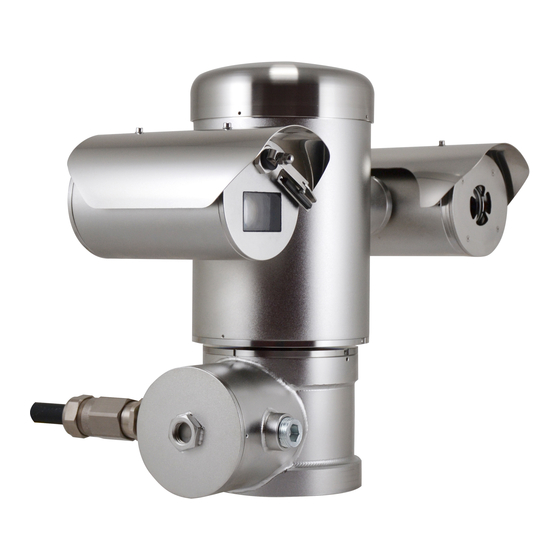
(Ton 15°C, Toff 23°C) and a built-in wiper. The PTZ device has an IP66 protection degree and its operating temperature is - 40°C to 60°C (-40°F / 140°F). ||MAXIMUS| PTZ includes integrated high- performance pan-and-tilt telemetry. Fig. 2 MAXIMUS MPX. MNVCMPXT_1607_EN... -
Page 12: Version For Thermal Imaging Cameras
4.1.1 Version for thermal imaging The high sensitivity NEdT 50mK at f/1.0 ensures an optimal thermal imaging. It supports 2x or 4x digital cameras zoom. The device can be provided with a thermal imaging A choice of lens sizes is offered between 35mm, camera, which is installed inside a second housing, 25mm and 9mm, depending on the detection whose window is made mainly of germanium which... -
Page 13: Preparing The Product For Use
5 Preparing the product for The device can only be considered to be switched off when the power supply has been disconnected and the connection cables to other devices have been removed. Any change that is not expressly approved by the manufacturer will invalidate both A power disconnect device must be the guarantee and certification. -
Page 14: Unpacking
5.2 Unpacking Single Mode/Multi Mode optical fiber version: • 1 explosion-proof P&T When the product is delivered, make sure that the • 1 sunshield (2 if version with thermal camera) package is intact and that there are no signs that it has been dropped or scratched. -
Page 15: Preparatory Work Before Installation
5.5 Preparatory work before 5.5.1 Fixing to parapet or ceiling mount installation Attach the adapter (01) to the bottom of the unit using 4 stainless steel (A4 class 80) socket flat head cap screw M10 x 20mm (02). Use appropriate tools for the installation. The particular nature of the site where the Make sure the thread are free of dirt and debris. -
Page 16: Fixing With Bracket
5.5.2 Fixing with bracket 5.5.3 Fixing the unit to the pole mount adapter or corner mount adapter The bracket can be fixed to the vertical wall. Use screws and wall fixing devices that can bear at least To install the component on a pole or at a wall corner, four times the weight of the unit. -
Page 17: Fixing With Corner Adapter
5.5.3.2 Fixing with corner adapter 5.5.4 Fixing the sunshield Fix the wall bracket to the corner mount adapter Remove the protective film before the using 4 washers, 4 stainless steel grower washers sunshield installation. 4 hexagon stainless steel bolts (A4 class 80) M10x30mm. -
Page 18: Installation
VIDEOTEC strongly recommend to test the device operation through the system’s software. configuration and performance in a office\laboratory Hardware adjustment is not required for inverted before putting it in the final installation site (6.3... -
Page 19: Connecting The Cables To The Base
6.3 Connecting the cables to the A connection compartment for cable entry with a 3/4” NPT threaded hole is located on the base of the base unit. A threaded cap gives access to a connection board CAUTION! The electrical system to which with removable connectors that help the installer to the unit is connected must be equipped connect the cables. -
Page 20: Cable Entry
Inside the connection compartment you'll find an To make the wirings, unplug the removable address and protocol board and a connectors board connector from the connection board, cable all the with removable connectors that make the cabling conductors on it and then plug the flying connector procedure easy. -
Page 21: Connection Of The Power Supply Line
6.5 Connection of the power Cable the wires on it. supply line Electrical connections must be performed with the power supply disconnected and ADDRESS & PROTOCOL the circuit-breaker open. FUS2 VIDEO - 1 When commencing installation make sure VIDEO - 2 that the specifications for the power supply for the installation correspond with those FUS1... - Page 22 Protective earth connections, use adequate cable The power supply cable should also be sections (up to 2.5mm² or AWG 14) covered by the silicone sheath supplied for this purpose (01). The silicone sheath must be fastened with the corresponding cable tie (02).
-
Page 23: Connections Of One Or More Video Cables
6.6 Connections of one or more 6.7 Connections of one or more video cables optical fiber The installation is type CDS (Cable Use adequate optical fiber. Distribution System), do not connect it to SELV circuits. The transmission of video signal or data can be done by optical fiber. -
Page 24: Connection Of The Ethernet Cable
• Insert the silicone sheath supplied for this purpose. Direct crimping is required if the product is connected to a hub or switch. Cross crimping is • Combine the 2 optical fibers using ST-ST adapter required if the product is connected directly to a PC. supplied. -
Page 25: Telemetry Lines Connections
The example below shows a typical installation. • Pass the telemetry cables through the entry device. • Take the J9 removable female connector from the connectors board and connect the telemetry wires to it. Switch Personal Computer FUS2 VIDEO - 1 VIDEO - 2 FUS1 VAR1... -
Page 26: Alarm And Relay Connections
6.10 Alarm and relay connections 6.10.1 Connecting an alarm with dry contact The alarm contacts are present on J3 connector. For a dry contact alarm (alarms AL1, AL2, AL3, AL4, AL5), implement the connection as shown in the figure. Dry contact Fig. -
Page 27: Unit Address, Communication Protocol And Baud Rate Setting
6.11 Unit address, 6.12 Configuration of the dip- communication protocol and switches baud rate setting Operating mode valid only on version with IP board. Before powering the device it must be correctly configured by setting the dip switches on the circuit The unit can be configured in one way only. -
Page 28: Baud Rate Configuration
6.14 Baud rate configuration 6.15 Setting of the serial communication lines To set the baud rate operate on DIP 2. To set the serial communication lines operate on DIP 2 DIP 2. The product is designed with two RS485 serial communication lines which can have various settings according to the positions of dip-switches 5 and 6 on the DIP selector. -
Page 29: Installation Examples
6.16 Installation examples 6.16.3 Two-way RS-422 line This setting allows full duplex communication 6.16.1 Two-way RS-485 TX/RX line according to the RS-422 standard. With this setting it is possible to obtain a bi- Line RS-485-1 is always in receiving mode (RS-422- directional, half/duplex, communication on the RX). -
Page 30: Serial Line Terminations
Every peripheral that is situated at the end of a line SENSORMATIC must be terminated using the appropriate dip-switch in order to prevent signal reflection and distortion. PELCO D VIDEOTEC MACRO Dip-switches 7 and 8 terminate serial lines RS-485-1 and RS-485-2 respectively. NETWORK SERIAL LINE TERMINATIONS (DIP 2) Tab. -
Page 31: Ground Connection
Do not explosive atmosphere. In this case contact use as a protective terminal. VIDEOTEC technical support. Verify that in the cap there isn’t dirt or debris. Lubricate the threaded part of the lid, of the connection compartment and the seal with technical vaseline oil lubricant. -
Page 32: Instructions For Safe Operation
7 Instructions for safe Use a 30mm wrench for tightly closing the threaded lid of the connection compartment. Make sure that operation there’s no gap between the threaded cap and the junction box tube after tightening the cap. 7.1 Safe operation Before proceeding with the following operations, make sure that the mains voltage is correct. -
Page 33: Safety Rules
8 Switching on 7.1.2 Safety rules Given the considerable weight of the system, use an The automatic pre-heating (De-Ice) process appropriate transport and handling system. could be started whenever the device is Before starting any operation, make sure the power switched on and the air temperature is supply is disconnected. -
Page 34: Configuration
9 Configuration 9.2 How to move around the menus 9.1 Using the OSM Each page of the OSM shows a list of parameters During normal operation of the unit, you can activate or sub-menus that can be selected by the operator. the OSM to select and configure advanced functions.. -
Page 35: How To Modify The Parameters
9.3 How to modify the 9.4 How to change the numeric parameters fields Move the cursor to the parameter to be changed and Move the cursor to the parameter to be changed and confirm. The field will start flashing, indicating that it confirm. -
Page 36: How To Change Text
9.5 How to change text The Confirm command (Zoom Tele) inserts the desired character. Move the cursor to the parameter to be changed and confirm. EDIT TEXT: AREA ------------------------ Text: TEXT AREA1 EDIT ZONE ↑ ------------------------ A B C D E F G ERASE 1 NR H I J K L M N... -
Page 37: Configuration Via Osm
9.6 Configuration via OSM 9.6.3 Camera menu Configuration: Sets one of the default 9.6.1 Main Menu configurations for the SONY module: • Standard: Sets the standard operating mode MAIN MENU for the camera. ------------------------ 1>LANGUAGE > • Low Light: Sets the operating mode for dimly 2 CAMERA >... -
Page 38: Zone Titling Menu
9.6.3.1 Zone Titling Menu 9.6.3.2 Zone Titling Menu (Edit Area) This function allows setting up to eight (variable Once inside the menu it is possibile to set the dimension) areas with titling option. following parameters: Enabling: To enable onscreen display of the Number: Selects the area to be edited. -
Page 39: Masking Menu
9.6.3.3 Masking Menu Setting the Start and Stop values of the Edit Dynamic masking allows the creation of up to a Zone menu to zero will disable text display. maximum of 24 masks so as to obtain the masking of If there are overlapping areas, the area with certain areas defined by the user. -
Page 40: Masking Menu (Edit Masks)
9.6.3.4 Masking Menu (Edit Masks) 9.6.3.5 How to create a new mask It allows you to configure the following parameters: Choose a disabled mask by selecting Mask Number from the Edit Masks menu. Select Edit Mask to edit it ( Mask Number: Allows you to choose the mask Fig. -
Page 41: How To Modify A Mask
9.6.3.6 How to modify a mask • When the desired result is obtained press the Iris Open. Choose an enabled mask by selecting Mask Number from the Edit Masks menu (Fig. 71, page 38). Select Edit Mask to edit it. MASK 1 PTZ Motions Enabled •... -
Page 42: Advanced Setting Menu
9.6.3.7 Advanced Setting Menu 9.6.3.8 Advanced Setting Menu (Zoom) Zoom Speed: Sets the speed of the zoom. The This menu is used to configure the SONY module. speed ranges between 0 (minimum speed) and Zoom: Allows access to the Zoom submenu. 7 (maximum speed). -
Page 43: Advanced Setting Menu (Focus)
9.6.3.9 Advanced Setting Menu (Focus) 9.6.3.10 Advanced Setting Menu (Exposure) It allows you to configure the following parameters: It allows you to configure the following parameters: Focus Speed: Sets the speed of the Focus. The 1-5. Mode: Sets the type of exposure control speed ranges between 0 (minimum speed) and Automatic, Manual, Shutter, Iris and Bright. -
Page 44: Advanced Setting Menu (Infrared)
9.6.3.11 Advanced Setting Menu (Infrared) The following table shows the inserted values with the corresponding effects on the SONY module lens. It allows you to configure the following parameters: CORRESPONDING VALUES/EFFECTS ON THE SONY MODULE LENS IR Mode: If set to OFF it forces the day mode in a continuous manner (the switching on of the illuminator, if present, is carried out by means of the light sensitive switch or by means of the... -
Page 45: Advanced Setting Menu (White Balance)
9.6.3.12 Advanced Setting Menu (White To avoid false switching, we recommend Balance) choosing the higher day switching It allows you to configure the following parameters: threshold and delay values. Mode: Sets the type of control on White Balance. The possible values are: INFRARED •... -
Page 46: Advanced Setting Menu (Other)
9.6.3.13 Advanced Setting Menu (Other) • Wind Mode: Sets the movements speed to adjust them to environments subject to Sharpness: Sets the sharpness value of the vibrations and/or windblasts. image. • High Perf: Establishes that all the movements High Resolution: Enables the High Resolution are carried out at the maximum possible function. -
Page 47: Manual Control Menu
9.6.4.1 Manual Control Menu 9.6.4.2 Manual Control Menu (Limits) Maximum Speed: Sets the maximum manual It allows you to configure the following parameters: speed. Pan Limits: Enables the limits of Pan. Fast Mode: Enables the Fast mode. When Pan Start: Sets the start limit of Pan. enabled, this option is used to move fastly the Pan End: Sets the end limit of Pan. -
Page 48: Preset Menu (Edit Preset)
9.6.4.4 Preset Menu (Edit Preset) 9.6.4.5 Preset Menu (Utility Preset) It allows you to configure the following parameters: It allows you to configure the following parameters: Number: The Preset number to be edited. Daytime A.Focus: Enables the use of the autofocus when loading the preset in daytime Enabling: Enabling preset. -
Page 49: Patrol Menu
9.6.4.6 Patrol Menu 9.6.4.8 Motion Recall Menu First Preset: First preset of the Patrol sequence. The unit can be configured so that, after a period of non-use, it carries out a movement function selected Last Preset: Last preset of the Patrol sequence. by the operator. -
Page 50: Advanced Menu
9.6.4.9 Advanced Menu 9.6.5 Display Menu Static Control: Enables control of the position PTZ Positions: If not on OFF, it is used to only when the pan & tilt is stopped select how the Pan, Tilt and Zoom positions are displayed on the screen. It is possible to Dynamic Control: Enables control of the select timed (1s, 3s and 5s) or constant (CONST) position only when the pan &... -
Page 51: Options Menu
9.6.6 Options Menu From the Alarms menu it is possible to access one of the menus (Alarms 1-5) to edit the alarms parameters. Ceiling Mount: When this mode is enabled the From these menus it is possible to set the following image and the movements controls are turned values: upsidedown. -
Page 52: Washer Menu
9.6.7 Washer Menu 9.6.8 Default Menu Delete Setup?: Resets all the parameters except The unit offers the possibility to use a wiper and to operate a pump to clean the glass. the Presets. Delete Preset?: Deletes all previously stored To configure the Washer put the lens of the camera in front of the nozzle of the Washer. -
Page 53: Thermal Camera Menu
9.6.10 Thermal Camera Menu Thermal Analysis: Allows access to the thermal analysis management submenu. Configuration: To set one of the preset Status: Allows access to the submenu configurations of the thermal camera. containing the technical features of the thermal • Standard: Sets the standard configuration of camera. -
Page 54: Flat Field Correction Menu
9.6.10.1 Flat Field Correction Menu Gain Mode: Allows the setting of dynamic gain range type: The thermal camera is fitted with an internal • High: This setting aims to maximize the mechanism which periodically improves the quality contrast and is especially suitable for of the images called Flat Field Correction (FFC). -
Page 55: Gain Switch Values
9.6.10.2 Gain Switch Values 9.6.10.3 Video Setup Menu It allows you to configure the following parameters: It allows you to configure the following parameters: High-Low Threshold: Sets the temperature Lut Polarity: Sets the hue of the image shot by threshold used by the High-Low Population the thermal camera. -
Page 56: Digital Data Enhancement Menu
9.6.10.4 Digital Data Enhancement menu DDE Mode: The DDE algorithm can be used to improve the details of the image and/or remove This menu allows configuration of the Digital Data noise. Displays the parameters of the selected Enhancement (DDE) algorithm. mode (Dynamic or Manual). -
Page 57: Gain Control Menu
9.6.10.5 Gain Control Menu • Information-based: The information-based algorithms retain more grey tones for the Once inside the Gain Control Configuration menu it is portions of the image with more information, possible to set one of the following parameters: assigning fewer grey tones to the portions Algorithm: Sets the type of automatic gain of the image with less information content. -
Page 58: Roi Setup Menu
9.6.10.6 ROI Setup Menu SSO Percent: Sets the value of Smart Scene Optimization (SSO). Defines the histogram Once inside the ROI Configuration Menu it is percentage which will be mapped linearly. possible to change the region of interest (ROI) used 10. -
Page 59: Thermal Analysis Menu
9.6.10.7 Thermal Analysis Menu 9.6.10.8 Thermal Analysis Menu (Spot Meter) Spot Meter: Allows access to the point Once inside the Point Measurement menu it is measurement configuration submenu. possible to set one of the following parameters: Isotherm: Allows access to the isotherm Mode: Enables the visualization of the taken management submenu. -
Page 60: Thermal Analysis Menu (Isotherm)
9.6.10.9 Thermal Analysis Menu (Isotherm) 9.6.10.10 Status Menu Once inside the Isotherm menu it is possible to Provides information about the installed thermal enable a special colouring for objects included within camera. Displays the internal camera temperature. the set temperature interval. The parameters which The first 4 values are expressed in hexadecimal manage this function are: format. -
Page 61: Configuration Of The Version With Ip Board
9.7 Configuration of the version Enter address: 192.168.0.100. At first access, enter the login and default password. with IP board Login: Admin (written with a capital A) 9.7.1 Minimum system requirements Password: 123456 Choose one of the following configurations, according to the number of channels to be controlled. -
Page 62: Wan Setting
9.7.2.1 WAN setting Continue by pressing the Install button. You carry out this procedure once and only once for each PC that is Keep the account and the password in a to have access to the device in the network. secure place. - Page 63 Then edit the other parameters, for example: Remove the hexagon set screw and unscrew the treaded cover of the junction box. • Date Setting: To set date and time. • Video Setting: To change resolution (720x576, 640x480, 352x288, 176x144) bit rate (setting between 28kbit and 3 Mbit).
-
Page 64: Installing The Nvr Software
Click on the Setup button in the control bar. Setup button Fig. 124 • Select VIDEOTEC NVR Professional and follow the instructions that appear on the screen. When you have completed installation, and the pan & tilts have been configured as appropriate (see Fig. -
Page 65: Controlling Ptz Movements
Media Source list. Check the Enable PTZ box. Click on Apply. This will automatically set the VIDEOTEC MACRO protocol at 38400 baud. Repeat the procedure for the other units to be controlled, directly from the PTZ setup menu ; just Fig. - Page 66 To control a unit via the control panel, select the unit To set the configuration parameters of the pan & tilt to be controlled by clicking with the mouse on the by means of OSM, enable the corresponding function corresponding video window, and then operate from using the control panel.
-
Page 67: Preset And Load Positions
9.7.3.2 Preset and load positions Set the preset positions for the other units in the same way. Before making these settings, we Close the NVR application and re-start it to recommend enabling Mouse PTZ control, save the settings. so that it is easier to move around in the position to be saved. -
Page 68: Instructions For Safe Operation
10 Instructions for safe 10.2 Saving the current position (Preset) operation 10.2.1 Quick save 10.1 Visualizing the state of the Using the control keyboard it is possible to save the pan & tilt current position (for further information, refer to the manual of the keyboard in use). -
Page 69: Restore A Preset Position (Scan)
10.3 Restore a Preset position 10.6 Recalling a pattern (Tour) (Scan) The Tour functioning mode allows the repetition of a previously recorded route in a continuous manner. Using the control keyboard it is possible to recall a The pan & tilt can store up to 3 Tours, each lasting no previously saved position (for further information, more than 2 minutes. -
Page 70: Recalling The Home Position
10.7 Recalling the Home position 10.9 Enabling the washer (Washer) Using the control keyboard it is possible to recall a previously saved Home position (Scan No. 1) Do not use the wiper when the outside (for further information, refer to the manual of the temperature is below 0°C or in case of ice. -
Page 71: Manual Correction Of A Preset Focusing
Preset command. The manual correction of the Preset works only if the Daytime/Nigh-time Autofocus fields are disabled (9.6.4.5 Preset Menu (Utility Preset), page 46). SPECIAL CONTROLS Action Control Protocol VIDEOTEC AMERICAN ERNITEC ONVIF (auxiliary PANASONIC PELCO D MACRO... -
Page 72: Special Controls
10.12 Special controls SPECIAL CONTROLS Action Control Protocol VIDEOTEC AMERICAN ERNITEC ONVIF (auxiliary PANASONIC PELCO D MACRO DYNAMICS command) Reboot the Save Preset 94 Save Preset 94 Save Preset 94 – Save Preset 94 Save Preset 94 device Ini+ Faster+ Zoom –... -
Page 73: Maintenance And Cleaning
Damage to this coating could When contacting VIDEOTEC for assistance please go interfere with the transparency of the surface to to the configuration and statistic page and send a infrared light. -
Page 74: Fuses Replacement
Whenever replacing the parts as indicated, 110Vac, 50/60Hz T 2A L 250V 5x20 T 4A H 250V 5x20 always use VIDEOTEC original spare parts 230Vac, 50/60Hz T 1A L 250V 5x20 T 4A H 250V 5x20 and meticulously follow the maintenance instructions supplied with every spare parts Tab. -
Page 75: Troubleshooting
13 Troubleshooting PROBLEM The monitor does not show the picture taken but shows an image of the type: Ask for assistance from skilled personnel if: • The unit is damaged after being dropped; Address : 1 • There is noticeable deterioration in performance Protocol : MACRO of the unit. - Page 76 SOLUTION Wait until the end of the pre-heating PROBLEM Error E5-IR TEMP. TOO HIGH or error procedure. If the air temperature is E6-IR FAULT. too low the unit will remain disabled CAUSE The infrared illuminator is not working and the following message will be properly.
-
Page 77: Technical Data
14 Technical data 14.1 MAXIMUS MPX 14.1.1 General If the device comes into contact with harsh substances, it is the responsibility of the user to take AISI 316L stainless steel construction suitable precautions to prevent damage and not Passivated and electropolished external surfaces compromise the type of protection. -
Page 78: Communications
Surge immunity: up to 2kV line to line, up to 4kV line Firmware updating from console in remote mode to earth (Class 4) (only VIDEOTEC MACRO and PELCO D protocols) 14.1.8 Certifications Up to 999 units, addressable by means of dip-... -
Page 79: Maximus Mpxt
14.2.4 Video 2 video outputs 75 Ohm 1Vpp (PAL/NTSC) Functions: Autopan, Preset, Patrol, Tour (maximum 3), Autoflip Maximum number of presets for protocol • VIDEOTEC MACRO: 250 • ERNITEC: 250 • PANASONIC: 250 • PELCO D: 99 • AMERICAN DYNAMICS: 95... -
Page 80: Communications
Surge immunity: up to 2kV line to line, up to 4kV line Firmware updating from console in remote mode to earth (Class 4) (only VIDEOTEC MACRO and PELCO D protocols) 14.2.8 Certifications Up to 999 units, addressable by means of dip-... -
Page 81: Electrical Rating
14.3 Electrical rating ELECTRICAL RATING Power supply Normal usage to be specified on product label Short term de-icing cicle. Peak maintaining a minimum internal temp at 5°C 230Vac 0.11A, 50/60Hz, 25.3W 0.52A, 50/60Hz, 120W 24Vac 1.08A, 50/60Hz, 25.9W 5A, 50/60Hz, 120W 120Vac 0.21A, 50/60Hz, 25.2W 1A, 50/60Hz, 120W... -
Page 82: Camera
14.5 Camera ANALOGUE CAMERAS AVAILABLE SONY Day/Night 36x SONY Day/Night 28x High sensi- tivity NTSC NTSC Optical zoom Wide Dynamic Range (Fix/Auto) – True progressive SCAN – Digital image stabilisation White balance Auto, ATW, Indoor, Outdoor (Fix/Auto), Auto, ATW, Indoor, Outdoor (Fix/Auto), Sodium Vapor Lamp (Fix/Auto) Sodium Vapor Lamp (Fix/Auto) High horizontal resolution... - Page 83 THERMAL CAMERAS AVAILABLE (RESOLUTION 160X120) Lens 19mm Lens 13mm Lens 9mm NTSC NTSC NTSC Image sensor Uncooled VOx microbolometer Uncooled VOx microbolometer Uncooled VOx microbolometer Resolution 160x120 160x120 160x120 160x120 160x120 160x120 Pixel dimensions 25μm 25μm 25μm Spectral response - long wave infrared (LWIR) from 7.5μm to 13.5μm from 7.5μm to 13.5μm from 7.5μm to 13.5μm...
- Page 84 EN - English - Instructions manual THERMAL CAMERAS AVAILABLE (RESOLUTION 336X256) Lens 35mm Lens 25mm Lens 19mm Lens 13mm Lens 9mm NTSC NTSC NTSC NTSC NTSC Image sensor Uncooled VOx microbolometer Uncooled VOx microbolometer Uncooled VOx microbolometer Uncooled VOx microbo- Uncooled VOx microbo- lometer lometer...
- Page 85 THERMAL CAMERAS (RESOLUTION 640X512) Lens 35mm Lens 25mm Lens 19mm Lens 13mm Lens 9mm NTSC NTSC NTSC NTSC NTSC Image sensor Uncooled VOx microbolo- Uncooled VOx microbolo- Uncooled VOx microbolo- Uncooled VOx microbolo- Uncooled VOx microbolo- meter meter meter meter meter Resolution 640x512...
-
Page 86: Technical Drawings
15 Technical drawings The dimensions of the drawings are in millimetres. Ø 138 Ø 138 N°4 M10 N°4 M10 Fig. 141 MAXIMUS MPX. MNVCMPXT_1607_EN... - Page 87 Ø 138 Ø 138 N°4 M10 N°4 M10 Fig. 142 MAXIMUS MPXT. MNVCMPXT_1607_EN...
-
Page 88: A Appendix - Marking Codes
EN - English - Instructions manual A Appendix - Marking codes A.1 ATEX marking 2 G Ex d ÐÐC T6 Gb T -40°C to +60°C ÏÐÐ ÐÐ 2 D Ex tb ÐÐÐC T85°C Db T -40°C to +60°C Ï IP66 Fig. -
Page 89: Iecex Marking
A.2 IECEx marking Ex d eeC T6 Gb T -40°C to +60°C Ex tb eeeC T85°C Db T -40°C to +60°C IP66 Fig. 144 Ex d ÐÐC Tfi -40°C to +60°C Ex-proof housing for potentially Gas group Gas temperature classification Protection level of the equipment Installation temperature range explosive environments... -
Page 90: Gas Group Classification
A.3 Gas group classification The table below shows the classification of some gases and vapours, according to the explosion-proof protection group and the temperature class. For a complete list see IEC/EN 60079-12 and IEC/EN 60079-20. GAS GROUP CLASSIFICATION Temperature class (Maximum surface temperature of the housing) 1 Class 450°C (842°F) 300°C (572°F) -
Page 91: B Appendix - Flamepath
B Appendix - Flamepath The maximum constructional gap (ic) is less than that required by Table 2 of EN 60079-1:2007 as detailed below: FLAMEPATH MAXIMUM GAP (MM) MINIMUM WIDTH (MM) COMMENT Between component drawings 0.249 25.4 Cylindrical joint sup- BRT2MPXALBPAN e BRT2MPXTAPINF ported by bearings Between component drawings 0.245... - Page 92 Email: info@videotec.com Tel. +33 1 60491816 - Fax +33 1 69284736 Email: info.fr@videotec.com Asia Pacific Videotec (HK) Ltd Americas Videotec Security, Inc. Flat 8, 19/F. On Dak Industrial Building, No. 2-6 Wah Sing Street Gateway Industrial Park, 35 Gateway Drive, Suite 100 Kwai Chung, New Territories - Hong Kong Plattsburgh, NY 12901 - U.S.A.
- Page 93 ITALIANO MAXIMUS MPX, MAXIMUS MPXT Brandeggio antideflagrante in acciaio inox Italiano - Manuale di istruzioni...
- Page 95 Sommario I T A L I A N O 1 Informazioni sul presente manuale ................7 1.1 Convenzioni tipografiche ............................. 7 2 Note sul copyright e informazioni sui marchi commerciali ........7 3 Norme di sicurezza ......................7 4 Identificazione ....................... 9 4.1 Descrizione e designazione del prodotto .......................
- Page 96 6.16.3 Linea RS-422 bidirezionale ..............................27 6.16.4 Linea RS-485 monodirezionale ............................27 6.17 Terminazione delle linee seriali ........................28 6.18 Configurazione del protocollo........................28 6.19 Configurazione dell'indirizzo ..........................28 6.20 Messa a terra .................................29 6.21 Chiusura del vano connessioni ........................29 7 Istruzioni di funzionamento in sicurezza ..............30 7.1 Funzionamento in condizioni di sicurezza ....................30 7.1.1 Messa in servizio ..................................30 7.1.2 Prescrizioni di sicurezza ...............................31...
- Page 97 9.6.6 Menù Opzioni ..................................49 9.6.6.1 Menù Allarmi ........................................49 9.6.7 Menù Impianto Di Lavaggio ..............................50 9.6.8 Menù Default ..................................50 9.6.9 Menù Info ....................................50 9.6.10 Menù Camera Termica ...............................51 9.6.10.1 Menù Correzione Flat Field ...................................52 9.6.10.2 Valori Cambio Guadagno ..................................53 9.6.10.3 Menù Configurazione Video .................................53 9.6.10.4 Menù...
- Page 98 13 Risoluzione dei problemi ..................73 14 Dati tecnici ......................... 75 14.1 MAXIMUS MPX ..............................75 14.1.1 Generale ....................................75 14.1.2 Meccanica ....................................75 14.1.3 Elettrico ....................................75 14.1.4 Video ......................................75 14.1.5 Comunicazioni ..................................76 14.1.6 Protocolli ....................................76 14.1.7 Ambiente ....................................76 14.1.8 Certificazioni ..................................76 14.2 MAXIMUS MPXT ..............................77 14.2.1 Generale ....................................77...
-
Page 99: Informazioni Sul Presente Manuale
1 Informazioni sul presente 3 Norme di sicurezza manuale ATTENZIONE! L’apparecchio deve essere collegato a un conduttore di terra (messa Prima di installare e utilizzare questa unità, leggere a terra protettiva). Tale collegamento attentamente questo manuale. Conservare questo deve essere eseguito solo attraverso il manuale a portata di mano come riferimento futuro. - Page 100 • Leggere le istruzioni. • L’apparecchio è controllato a distanza e può pertanto cambiare posizione in qualsiasi • Conservare le istruzioni. momento. Installare l’apparecchio in modo da • Osservare tutte le avvertenze. evitare incidenti causati dal contatto con parti • Attenersi a tutte le istruzioni. in movimento, facendo sì...
-
Page 101: Identificazione
Il dispositivo PTZ è dotato di un grado di protezione IP66 e funziona a temperature comprese tra - 40°C e 60°C (-40°F / 140°F). MAXIMUS PTZ presenta inoltre una telemetria integrata ad alta prestazione per la movimentazione Fig. 2 MAXIMUS MPX. orizzontale/verticale. MNVCMPXT_1607_IT... -
Page 102: Versione Per Telecamere Termiche
4.1.1 Versione per telecamere termiche L’elevata sensibilità NEdT 50mK a f/1,0 garantisce un’acquisizione ottimale di immagini termiche. Il dispositivo può essere provvisto anche di una Supporta zoom digitale 2x o 4x. telecamera termica per l’acquisizione delle immagini, Viene proposta una scelta di diverse lunghezze focali installata in una seconda custodia, la cui finestra, tra 35mm, 25mm e 9mm, a seconda delle distanze di composta principalmente da germanio, garantisce... -
Page 103: Preparazione Del Prodotto Per L'utilizzo
5 Preparazione del prodotto L’apparecchio si considera disattivato per l'utilizzo soltanto quando l’alimentazione è disinserita e i cavi di collegamento con altri dispositivi sono stati rimossi. Qualsiasi cambiamento non espressamente approvato dal costruttore fa decadere la L’impianto deve essere dotato di garanzia e la certificazione. -
Page 104: Disimballaggio
5.2 Disimballaggio Versione fibra ottica Single Mode/Multi Mode: • 1 brandeggio antideflagrante Alla consegna del prodotto verificare che l'imballo • 1 tettuccio (2 nella versione con telecamera sia integro e non abbia segni evidenti di cadute o termica) abrasioni. • 1 documento Importanti istruzioni per la sicurezza In caso di evidenti segni di danno all'imballo contattare immediatamente il fornitore. -
Page 105: Lavoro Preparatorio Prima Dell'installazione
5.5 Lavoro preparatorio prima 5.5.1 Fissaggio a parapetto o a soffitto dell’installazione Collegare l’adattatore (01) al fondo dell’unità utilizzando 4 viti a testa svasata piana (02) con esagono incassato M10x20mm in acciaio inox (A4 Eseguire l’installazione utilizzando utensili classe 80). adeguati. -
Page 106: Fissaggio Con Staffa
5.5.2 Fissaggio con staffa 5.5.3 Fissaggio con imbracatura da palo o modulo adattatore angolare Il supporto può essere fissato direttamente ad un muro verticale. Utilizzare viti e dispositivi di fissaggio Per installare l'unità su imbracatura da palo o in a muro che possono sostenere un peso almeno 4 corrispondenza di un angolo prima di tutto fissare volte superiore a quello dell’unità. -
Page 107: Fissaggio Con Modulo Angolare
5.5.3.2 Fissaggio con modulo angolare 5.5.4 Fissaggio del tettuccio Per fissare la staffa di supporto a muro al modulo Prima di fissare il tettuccio della custodia adattatore angolare, utilizzare 4 rondelle piane, rimuovere la pellicola protettiva. 4 rondelle grower in acciaio inox e 4 viti a testa esagonale in acciaio inox (A4 classe 80) da Fissare il tettuccio alla custodia utilizzando viti e M10x30mm. -
Page 108: Installazione
Assicurarsi che l’installazione sia conforme riconfigurazione delle funzioni di orientamento alle norme locali. e controllo della telecamera avviene mediante il VIDEOTEC raccomanda di testare la configurazione software di sistema. e le prestazioni dell’apparecchio in un’officina o Il funzionamento in posizione invertita non richiede laboratorio prima di collocarlo nel sito di installazione alcuna modifica dell’hardware. -
Page 109: Collegamento Dei Cavi Alla Base
6.3 Collegamento dei cavi alla Sulla base dell’unità è presente un vano connessioni con foro filettato da 3/4” NPT per l’ingresso dei cavi. base Svitando il coperchio filettato si accede a una scheda di connettori dotata di connettori rimovibili ATTENZIONE! L’impianto elettrico al quale che facilitano il collegamento dei cavi durante è... -
Page 110: Ingresso Cavi
All’interno del vano connessioni è presente una Per effettuare i cablaggi, scollegare il connettore scheda di configurazione delle linee seriali e rimovibile dalla scheda, cablare tutti i cavi elettrici una scheda dotata di connettori rimovibili che e reinserire il connettore volante come illustrato in semplificano la procedura di cablaggio. -
Page 111: Collegamento Della Linea Di Alimentazione
6.5 Collegamento della linea di Collegare i cavi al connettore. alimentazione Eseguire le connessioni elettriche in assenza di alimentazione e con dispositivo ADDRESS & PROTOCOL di sezionamento aperto. FUS2 VIDEO - 1 All’atto dell’installazione controllare che VIDEO - 2 le caratteristiche di alimentazione fornite dall’impianto corrispondano a quelle FUS1 VAR1... - Page 112 Per eseguire collegamenti di messa a terra protettiva Il cavo di alimentazione deve essere utilizzare cavi di sezione adeguata (fino a 2,5mm² o coperto con la guaina siliconica presente AWG 14). nella dotazione (01). La guaina siliconica deve essere fissata con l’apposita fascetta (02).
-
Page 113: Collegamento Di Uno O Più Cavi Video
6.6 Collegamento di uno o più 6.7 Collegamento di una o più cavi video fibre ottiche L'impianto è di tipo CDS (Cable Distribution Utilizzare fibre ottiche adeguate. System), non collegare a circuiti SELV. La trasmissione del video e dati può avvenire tramite Per ridurre il rischio di incendio usare fibra ottica. -
Page 114: Collegamento Del Cavo Di Rete Ethernet
• Inserire la guaina siliconica presente nella Va effettuata una crimpatura diretta se si collega dotazione. il prodotto a un hub o a uno switch. Va effettuata una crimpatura incrociata se si collega il prodotto • Unire le 2 fibre ottiche mediante l’adattatore ST-ST direttamente a un PC. -
Page 115: Collegamento Delle Linee Di Telemetria
Una installazione tipica è quella riportata • Far scorrere i cavi telemetrici lungo il dispositivo di nell’esempio sottostante. entrata. • Estrarre il connettore femmina rimovibile J9 dalla scheda di connessione e collegare la scheda ai cavi telemetrici. Switch Personal Computer FUS2 VIDEO - 1 VIDEO - 2... -
Page 116: Collegamento Degli Allarmi E Dei Relè
6.10 Collegamento degli allarmi 6.10.1 Collegamento allarme con contatto pulito e dei relè Nel caso di allarme a contatto pulito (allarmi AL1, I contatti degli allarmi sono presenti sul connettore AL2, AL3, AL4, AL5), eseguire il collegamento come illustrato in figura. Contatto pulito Fig. -
Page 117: Impostazione Dell'indirizzo Di Unità, Del Protocollo Di Comunicazione E Della Velocità Di Trasmissione
6.11 Impostazione dell’indirizzo 6.12 Configurazione dei dip- di unità, del protocollo di switch comunicazione e della velocità di Collegamento valido solo su versione con trasmissione scheda IP. Prima di alimentare il dispositivo, è necessario Esiste un modo unico per configurare l’unità. configurarlo correttamente tramite i dip switch Impostare i DIP esattamente come riportato in presenti nell’apposita scheda. -
Page 118: Configurazione Del Baud Rate
6.14 Configurazione del baud 6.15 Configurazione delle linee di rate comunicazione seriali Per impostare il baud rate agire sul DIP 2. Per impostare le linee di comunicazioni seriali agire sul DIP 2. DIP 2 Il prodotto prevede due linee seriali di comunicazione RS485, che possono essere configurate in vari modi secondo la posizione dei dip-switch 5 e 6 del selettore del DIP. -
Page 119: Esempi Di Installazione
6.16 Esempi di installazione 6.16.3 Linea RS-422 bidirezionale Questa impostazione consente la comunicazione in 6.16.1 Linea RS-485 TX/RX bidirezionale full duplex secondo lo standard RS-422. Questa impostazione permette di ottenere una La linea RS-485-1 è sempre in ricezione (RS-422-RX). comunicazione bidirezionale half-duplex sulla linea La linea RS-485-2 è... -
Page 120: Terminazione Delle Linee Seriali
SENSORMATIC seriale (Tab. 7, pagina 28). PELCO D Ogni periferica che si trovi a fine linea deve essere VIDEOTEC MACRO terminata utilizzando l’apposito dip-switch in modo NETWORK da evitare riflessioni e deformazioni del segnale. I dip-switch 7 e 8 terminano rispettivamente le linee Tab. -
Page 121: Messa A Terra
In questo caso del prodotto. Da non utilizzare come rivolgersi al servizio tecnico di VIDEOTEC. morsetto di protezione. Verificare che non vi sia la presenza di sporcizia o residui. Lubrificare la parte filettata del coperchio, del vano connessioni e la guarnizione con lubrificante a base di olio di vaselina tecnica. -
Page 122: Istruzioni Di Funzionamento In Sicurezza
7 Istruzioni di Serrare ermeticamente il tappo filettato del vano connessioni con una chiave da 30mm. Dopo la funzionamento in sicurezza chiusura, assicurarsi che non vi sia spazio tra il tappo filettato e il tubo del vano connessioni. 7.1 Funzionamento in condizioni di sicurezza Prima di effettuare le seguenti operazioni assicurarsi che la tensione di alimentazione... -
Page 123: Prescrizioni Di Sicurezza
8 Accensione 7.1.2 Prescrizioni di sicurezza Dato il peso considerevole dell’apparecchio, utilizzare La procedura di preriscaldamento un sistema di trasporto e movimentazione adeguato. automatico (De-Ice) si potrebbe attivare Assicurarsi di avere scollegato l’alimentazione prima tutte le volte che il dispositivo viene acceso di eseguire qualsiasi operazione. -
Page 124: Configurazione
9 Configurazione 9.2 Come muoversi nei menù Ogni videata dell’OSM presenta una lista di parametri 9.1 Uso dell'OSM o di sottomenù che possono essere selezionati dall’operatore. Per scorrere i vari parametri muovere il Durante il normale funzionamento dell'unità cursore agendo sul joystick (alto e basso). è... -
Page 125: Come Modificare I Parametri
9.3 Come modificare i parametri 9.4 Come modificare i campi numerici Spostarsi con il cursore in corrispondenza del parametro che si intende modificare e confermare. Spostarsi con il cursore in corrispondenza del Il campo comincerà a lampeggiare indicando che parametro che si intende modificare e confermare. è... -
Page 126: Come Modificare I Testi
9.5 Come modificare i testi Il comando Conferma (Zoom Tele) inserisce il carattere desiderato. Spostarsi con il cursore in corrispondenza del parametro che si intende modificare e confermare. EDIT TEXT: AREA ------------------------ Text: TEXT AREA1 MODIFICA AREA ↑ ------------------------ A B C D E F G ERASE 1 NR H I J K L M N... -
Page 127: Configurazione Tramite Osm
9.6 Configurazione tramite OSM 9.6.3 Menù telecamera Configurazione: Imposta una delle 9.6.1 Menù Principale configurazioni predefinite per il modulo SONY: • Standard: Imposta la modalità di MENU PRINCIPALE funzionamento standard della telecamera. ------------------------ 1>LINGUA > • Low Light: Imposta la modalità di 2 TELECAMERA >... -
Page 128: Menù Titolazione Aree
9.6.3.1 Menù Titolazione Aree 9.6.3.2 Menù Titolazione Aree (Modifica Area) Questa funzione consente di impostare fino a otto zone (di dimensioni variabili) con possibilità di Una volta entrati nel menù è possibile impostare i titolazione. seguenti parametri: Abilitazione: Abilitare la visualizzazione sullo Numero: Seleziona l’area da modificare. -
Page 129: Menù Mascheratura
9.6.3.3 Menù Mascheratura Ponendo a zero i valori di Start e Stop La mascheratura dinamica permette di creare fino del menù Modifica Area si disabilita la ad un massimo di 24 maschere in modo da ottenere visualizzazione della scritta. In caso di l’oscuramento di particolari aree definite dall’utente. -
Page 130: Menù Mascheratura (Modifica Maschere)
9.6.3.4 Menù Mascheratura (Modifica 9.6.3.5 Come creare una nuova maschera Maschere) Scegliere una maschera non abilitata selezionando dal menù Modifica Maschere la voce Maschera Permette di configurare i seguenti parametri: Numero. Per modificarla seleziona la voce Modifica Maschera Numero: Permette di scegliere su Maschera (Fig. -
Page 131: Come Modificare Una Maschera
9.6.3.6 Come modificare una maschera • Una volta ottenuto il risultato desiderato premere il pulsante Iris Open. Scegliere una maschera abilitata selezionando dal menù Modifica Maschere la voce Maschera Numero ( Fig. 71, pagina 38). Per modificarla seleziona la voce MASK 1 Movimenti PTZ Abilitati Modifica Maschera. -
Page 132: Menù Configurazioni Avanzate
9.6.3.7 Menù Configurazioni Avanzate 9.6.3.8 Menù Configurazioni Avanzate (Zoom) Accedendo a questo menù è possibile configurare il modulo SONY. Velocità Zoom: Imposta la velocità dello zoom. I valori di velocità sono compresi tra 0 (minima Zoom: Permette di accedere al sottomenù velocità) e 7 (massima velocità). -
Page 133: Menù Configurazioni Avanzate (Focus)
9.6.3.9 Menù Configurazioni Avanzate 9.6.3.10 Menù Configurazioni Avanzate (Focus) (Esposizione) Permette di configurare i seguenti parametri: Permette di configurare i seguenti parametri: Velocità Focus: Imposta la velocità del Focus. 1-5. Modo: Imposta il tipo di controllo I valori di velocità sono compresi tra 0 (minima dell’esposizione: Automatica, Manuale, Shutter, velocità) e 7 (massima velocità). -
Page 134: Menù Configurazioni Avanzate (Infrarosso)
9.6.3.11 Menù Configurazioni Avanzate La tabella seguente riporta la corrispondenza tra i valori introdotti e l’effetto sull’ottica del modulo (Infrarosso) SONY. Permette di configurare i seguenti parametri: CORRISPONDENZA VALORE/EFFETTO OTTICA MODULO SONY Modo IR: Se settato OFF forza la modalità diurna in modo continuativo (l’accensione dell'illuminatore, se presente, si effettua tramite interruttore crepuscolare o apposito comando... -
Page 135: Menù Configurazioni Avanzate (Bilanciamento Bianco)
9.6.3.12 Menù Configurazioni Avanzate Per evitare false commutazioni si consiglia (Bilanciamento Bianco) di scegliere i valori di soglia e ritardo di Permette di configurare i seguenti parametri: commutazione diurna più elevati. Modo: Imposta il tipo di controllo del bilanciamento del bianco. I valori possibili sono: INFRAROSSO •... -
Page 136: Menù Configurazioni Avanzate (Altro)
9.6.3.13 Menù Configurazioni Avanzate • Wind Mode: Imposta le velocità dei movimenti in modo da renderle adatte ad (Altro) ambienti soggetti a vibrazioni e/o raffiche di Nitidezza: Imposta il valore della nitidezza vento. dell’immagine. • High Perf: Impone che i movimenti siano Alta Risoluzione: Abilita la funzione Alta eseguiti alla massima velocità... -
Page 137: Menù Controllo Manuale
9.6.4.1 Menù Controllo Manuale 9.6.4.2 Menù Controllo Manuale (Limiti) Velocità Massima: Imposta la velocità manuale Permette di configurare i seguenti parametri: massima. Limiti Pan: Abilita i limiti del Pan. Modalità Fast: Attiva la modalità Fast. Questa Pan Inizio: Imposta il limite iniziale del Pan. opzione, se attiva, permette di muovere Pan Fine: Imposta il limite finale del Pan. -
Page 138: Menù Preset (Modifica Preset)
9.6.4.4 Menù Preset (Modifica Preset) 9.6.4.5 Menù Preset (Utilità Preset) Permette di configurare i seguenti parametri: Permette di configurare i seguenti parametri: Numero: Il numero del Preset che si desidera A.Focus Giorno: Abilita l’utilizzo dell’autofocus modificare. durante il richiamo dei preset in modalità giorno. -
Page 139: Menù Patrol
9.6.4.6 Menù Patrol 9.6.4.8 Menù Richiamo Movimenti Primo Preset: Primo preset della sequenza di È possibile configurare l'unità in modo che, dopo un Patrol. certo periodo di inattività, esegua automaticamente una funzione di movimento scelta dall’operatore. Ultimo Preset: L’ultimo preset della sequenza di Patrol. -
Page 140: Menù Avanzate
9.6.4.9 Menù Avanzate 9.6.5 Menù Visualizzazioni Controllo Statico: Abilita il controllo della Posizione PTZ: Se posto diverso da OFF, posizione solo quando il brandeggio è fermo. permette di selezionare la modalità con la quale vengono visualizzate sullo schermo le posizioni Controllo Dinamico: Abilita il controllo della di Pan, Tilt e Zoom. -
Page 141: Menù Opzioni
9.6.6 Menù Opzioni Dal menù Allarmi è possibile accedere ad uno dei menù (Allarme 1-5) dove modificare i parametri degli Montaggio A Soffitto: Abilitando questa allarmi. modalità si ha il capovolgimento dell’immagine Da questi menu è possibile impostare i seguenti e dei comandi di direzione. -
Page 142: Menù Impianto Di Lavaggio
9.6.7 Menù Impianto Di Lavaggio 9.6.8 Menù Default Cancella Setup?: Ripristina tutti i parametri L'unità offre la possibilità di utilizzare un tergicristallo e di azionare una pompa per la pulizia del vetro. eccetto i preset. Cancella Preset?: Elimina tutti i preset Per configurare l’impianto di lavaggio posizionare l’obiettivo della telecamera di fronte all’ugello precedentemente memorizzati. -
Page 143: Menù Camera Termica
9.6.10 Menù Camera Termica Analisi Termica: Permette di entrare nel sottomenù per la gestione dell’analisi termica. Configurazione: Imposta una delle Status: Permette di entrare nel sottomenù in cui configurazioni predefinite della camera termica. sono riportate le caratteristiche tecniche della • Standard: Imposta la configurazione camera termica. -
Page 144: Menù Correzione Flat Field
9.6.10.1 Menù Correzione Flat Field Modo Guadagno: Permette di selezionare il tipo di range dinamico di guadagno: La camera termica ha un meccanismo interno per • High: Questa impostazione è pensata migliorare periodicamente la qualità delle immagini: per massimizzare il contrasto ed è la correzione Flat Field (FFC). -
Page 145: Valori Cambio Guadagno
9.6.10.2 Valori Cambio Guadagno 9.6.10.3 Menù Configurazione Video Permette di configurare i seguenti parametri: Permette di configurare i seguenti parametri: Soglia Alto-Basso: Imposta la soglia di Polarità Lut: Imposta il tipo di colorazione temperatura usata dal parametro Popolamento dell’immagine inquadrata dalla camera termica. Alto-Basso per forzare la commutazione in Avviso FFC: Imposta la durata della modalità... -
Page 146: Menù Digital Data Enhancement
9.6.10.4 Menù Digital Data Enhancement DDE Mode: L'algoritmo DDE può essere impiegato per migliorare i dettagli Questo menù permette di configurare l'algoritmo dell'immagine e/o rimuovere il rumore. In base Digital Data Enhancement (DDE). alla modalità selezionata (Dynamic o Manual) DDE Mode: L'algoritmo DDE può essere verranno visualizzati i relativi parametri. -
Page 147: Menù Controllo Guadagno
9.6.10.5 Menù Controllo Guadagno • Information-based: Gli algoritmi Information-based riservano più toni di grigio Una volta entrati nel menù Configurazione Controllo per le porzioni di immagine con maggiori Guadagno è possibile impostare uno dei seguenti informazioni assegnando meno toni di parametri: grigio alle porzioni di immagine con minor Algoritmo: Imposta il tipo di controllo... -
Page 148: Menù Configurazione Roi
9.6.10.6 Menù Configurazione ROI SSO Percent: Imposta il valore della Smart Scene Optimization (SSO). Definisce la Una volta entrati nel menù Configurazione ROI è percentuale dell'istogramma che sarà mappata possibile modificare la regione di interesse (ROI) usata linearmente. dall’algoritmo AGC per calcolare i livelli di contrasto e 10. -
Page 149: Menù Analisi Termica
9.6.10.7 Menù Analisi Termica 9.6.10.8 Menù Analisi Termica (Punto di Misura) Punto Di Misura: Permette di entrare nel sottomenù per la configurazione del punto di Una volta entrati nel menù Punto di Misura è misura. possibile impostare uno dei seguenti parametri: Isoterma: Permette di entrare nel sottomenù... -
Page 150: Menù Analisi Termica (Isoterma)
9.6.10.9 Menù Analisi Termica (Isoterma) 9.6.10.10 Menù Stato Una volta entrati nel menù Isoterma è possibile Fornisce informazioni sulla telecamera termica attivare una speciale colorazione per oggetti installata. Visualizza la temperatura interna della compresi nell’intervallo di temperatura impostato. telecamera. I primi 4 valori sono espressi in formato I parametri che gestiscono questa funzione sono i esadecimale. -
Page 151: Configurazione Scheda Ip
9.7 Configurazione Scheda IP Accedere all’indirizzo: 192.168.0.100. Al primo accesso immettere login e password di 9.7.1 Requisiti minimi del PC default. In base al numero di canali da controllare scegliere Login: Admin (scritto con la A maiuscola) una delle configurazioni seguenti. Password: 123456 CANALI Intel Core 2... -
Page 152: Configurazione Wan
9.7.2.1 Configurazione WAN Procedere premendo il pulsante Install. Questa procedura si esegue una solo volta per ciascun PC Conservare l’account e la password in un che deve accedere al brandeggio in rete. posto sicuro. In seguito appare la finestra Video Live. Impostare in seguito l’indirizzo IP statico, con il quale si accederà... - Page 153 Modificare poi gli altri parametri come ad esempio: Rimuovere il grano di sicurezza e svitare il tappo filettato. • Date Setting: Per l’impostazione della data ed ora. • Video Setting: Per cambio risoluzione (720x576, 640x480, 352x288, 176x144) bitrate (impostabile da 28kbit a 3 Mbit). Per la telemetria lasciare le impostazioni di default.
-
Page 154: Installazione Del Software Nvr
Cliccare nella barra comandi il pulsante Setup. Pulsante Setup Fig. 124 • Selezionare la voce VIDEOTEC NVR Professional e seguire le indicazioni riportate nel programma. Al termine della procedura di installazione, e dopo Fig. 126 aver configurato opportunamente i brandeggi Quindi Setup Camera. -
Page 155: Controllo Movimenti Ptz
Spuntare la casella Enable PTZ. Dare apply. In questo modo si imposta in automatico il protocollo VIDEOTEC di tipo MACRO a 38400baud. Ripetere la procedura per le altre unità da controllare. Direttamente dal menu setup PTZ selezionare le Fig. 128 altre unità... - Page 156 Per un controllo dell’unità tramite pannello comandi, Volendo impostare i parametri di configurazione del selezionare l’unità da contollare tramite click con brandeggio tramite OSM, attivare la relativa funzione mouse sulla finestra video relativa, e poi agire sul sempre tramite pannello comandi. pannello comandi.
-
Page 157: Preset E Richiamo Posizioni
9.7.3.2 Preset e richiamo posizioni Allo stesso modo impostare le posizioni di preset delle altre unità. Prima di eseguire queste impostazioni, è Chiudere il programma NVR e riavviare consigliabile attivare il controllo Mouse affichè le impostazioni abbiano effetto. PTZ per poter muoversi agevolmente nella posizione da memorizzare. -
Page 158: Istruzioni Di Funzionamento In Sicurezza
10 Istruzioni di 10.2 Salvataggio della posizione attuale (Preset) funzionamento in sicurezza 10.2.1 Salvataggio veloce 10.1 Visualizzazione dello stato Tramite la tastiera di controllo è possibile salvare del brandeggio la posizione attuale (per ulteriori informazioni fare riferimento al manuale della tastiera utilizzata). Durante il normale funzionamento, a scelta Durante la fase di salvataggio è... -
Page 159: Richiamo Di Una Posizione Di Preset (Scan)
10.3 Richiamo di una posizione di 10.6 Richiamo di un percorso Preset (Scan) (Tour) Tramite la tastiera di controllo è possibile richiamare La modalità di funzionamento Tour permette di una posizione precedentemente salvata (per ulteriori ripetere un percorso precedentemente registrato in informazioni fare riferimento al manuale della tastiera modo continuo. -
Page 160: Richiamo Della Posizione Di Home
10.7 Richiamo della posizione di 10.9 Attivazione dell'impianto di Home lavaggio (Washer) Tramite la tastiera di controllo è possibile richiamare Non utilizzare il tergicristallo quando la la posizione di Home (Scan n.1) precedentemente temperatura esterna è inferiore a 0°C o in salvata (per ulteriori informazioni fare riferimento al presenza di ghiaccio. -
Page 161: Correzione Manuale Della Messa A Fuoco Di Un Preset
Preset. La correzione manuale del Preset ha effetto solo se i campi Autofocus Giorno/Notte sono disabilitati (9.6.4.5 Menù Preset (Utilità Preset), pagina 46). COMANDI SPECIALI Azione Comando Protocollo VIDEOTEC AMERICAN ERNITEC ONVIF (auxiliary PANASONIC PELCO D MACRO... -
Page 162: Comandi Speciali
10.12 Comandi speciali COMANDI SPECIALI Azione Comando Protocollo VIDEOTEC AMERICAN ERNITEC ONVIF (auxiliary PANASONIC PELCO D MACRO DYNAMICS command) Reboot dispo- Salvare Preset 94 Salvare Preset 94 Salvare Preset 94 – Salvare Preset 94 Salvare Preset 94 sitivo Ini+ Faster+ Zoom –... -
Page 163: Manutenzione E Pulizia
Fig. 139 visualizzazione dei dati statistici Deve essere fatta con sapone neutro diluito con Per contattare il servizio tecnico di VIDEOTEC, aprire acqua. Prestare attenzione a non graffiare o rigare la pagina delle configurazioni e delle statistiche e la superficie esterna trattata con carbon coating. -
Page 164: Sostituzione Dei Fusibili
I nuovi fusibili dovranno rispettare le indicazioni fornite in tabella. In caso di danneggiamento la sostituzione SOSTITUZIONE DEI FUSIBILI o riparazione delle parti interessate deve essere eseguita da VIDEOTEC o sotto la sua Tensione di Fusibile (FUS1) Fusibile (FUS2) alimentazione supervisione. -
Page 165: Risoluzione Dei Problemi
13 Risoluzione dei problemi PROBLEMA Sul monitor non viene visualizzata l’immagine ripresa ma una schermata del tipo: Richiedere l’intervento di personale qualificato quando: Indirizzo : 1 • L’unità si è danneggiata a seguito di una caduta; Protocollo: MACRO • Le prestazioni dell’unità hanno avuto un evidente RS485-1:38400 N81 RX peggioramento;... - Page 166 SOLUZIONE Attendere il termine della procedura PROBLEMA Errore E5-IR TEMP. TROPPO ALTA di preriscaldamento. Se la oppure errore E6-IR GUASTO. temperatura ambiente è troppo bassa CAUSA Errato funzionamento l'unità rimane bloccata visualizzando dell'illuminatore. la seguente schermata: SOLUZIONE Contattare il centro di assistenza autorizzato.
-
Page 167: Dati Tecnici
14 Dati tecnici 14.1 MAXIMUS MPX 14.1.1 Generale Qualora l'apparecchiatura venga a contatto con sostanze aggressive è responsabilità dell'utente Costruzione in acciaio Inox AISI 316L prendere precauzioni adeguate a prevenirne il Superfici esterne passivate ed elettrolucidate danneggiamento e a non comprometterne il tipo di protezione. -
Page 168: Comunicazioni
Immunità agli impulsi: fino a 2kV tra linea e linea, fino Aggiornamento firmware da console in remoto (solo a 4kV tra linea e terra (Classe 4) protocolli VIDEOTEC MACRO e PELCO D) 14.1.8 Certificazioni Fino a 999 unità indirizzabili via dip-switch ATEX (EN 60079-0: 2012, EN 60079-1: 2007, EN 60079- MPX, modalità... -
Page 169: Maximus Mpxt
14.2.4 Video 2 uscite video 75 Ohm 1Vpp (PAL/NTSC) Funzioni: Autopan, Preset, Patrol, Tour (massimo 3), Autoflip Numero massimo di preset per protocollo • VIDEOTEC MACRO: 250 • ERNITEC: 250 • PANASONIC: 250 • PELCO D: 99 • AMERICAN DYNAMICS: 95 Stringa di 16 caratteri per titolazione dell’area e dei... -
Page 170: Comunicazioni
Immunità agli impulsi: fino a 2kV tra linea e linea, fino Aggiornamento firmware da console in remoto (solo a 4kV tra linea e terra (Classe 4) protocolli VIDEOTEC MACRO e PELCO D) 14.2.8 Certificazioni Fino a 999 unità indirizzabili via dip-switch ATEX (EN 60079-0: 2012, EN 60079-1: 2007, EN 60079- MPXT, modalità... -
Page 171: Consumo Elettrico
14.3 Consumo elettrico CONSUMO ELETTRICO Tensione di Normale utilizzo da specificare nella targhetta di Massimo consumo durante la procedura di preriscal- alimentazione marcatura damento automatico (De-Ice) per mantenere una temperatura minima interna 5°C 230Vac 0.11A, 50/60Hz, 25.3W 0.52A, 50/60Hz, 120W 24Vac 1.08A, 50/60Hz, 25.9W 5A, 50/60Hz, 120W... -
Page 172: Telecamere
14.5 Telecamere TELECAMERE ANALOGICHE DISPONIBILI SONY Day/Night 36x SONY Day/Night 28x Alta sensibilità NTSC NTSC Zoom ottico Wide Dynamic Range (Fix/Auto) – True progressive SCAN – Stabilizzazione immagine digitale Bilanciamento del bianco Auto, ATW, Indoor, Outdoor (Fix/Auto), Auto, ATW, Indoor, Outdoor (Fix/Auto), Sodium Vapor Lamp (Fix/Auto) Sodium Vapor Lamp (Fix/Auto) Elevata risoluzione orizzontale... - Page 173 TELECAMERE TERMICHE DISPONIBILI (RISOLUZIONE 160X120) Obiettivo 19mm Obiettivo 13mm Obiettivo 9mm NTSC NTSC NTSC Sensore immagini Microbolometro non raffreddato (VOx) Microbolometro non raffreddato (VOx) Microbolometro non raffreddato (VOx) Risoluzione 160x120 160x120 160x120 160x120 160x120 160x120 Dimensioni pixel 25μm 25μm 25μm Risposta spettrale - Infrarossi onda lunga (LWIR) da 7.5μm a 13.5μm da 7.5μm a 13.5μm...
- Page 174 IT - Italiano - Manuale di istruzioni TELECAMERE TERMICHE DISPONIBILI (RISOLUZIONE 336X256) Obiettivo 35mm Obiettivo 25mm Obiettivo 19mm Obiettivo 13mm Obiettivo 9mm NTSC NTSC NTSC NTSC NTSC Sensore immagini Microbolometro non raffred- Microbolometro non raffred- Microbolometro non raffred- Microbolometro non Microbolometro non dato (VOx) dato (VOx)
- Page 175 TELECAMERE TERMICHE (RISOLUZIONE 640X512) Obiettivo 35mm Obiettivo 25mm Obiettivo 19mm Obiettivo 13mm Obiettivo 9mm NTSC NTSC NTSC NTSC NTSC Sensore immagini Microbolometro non raffred- Microbolometro non raffred- Microbolometro non raffred- Microbolometro non raffred- Microbolometro non raffred- dato (VOx) dato (VOx) dato (VOx) dato (VOx) dato (VOx)
-
Page 176: Disegni Tecnici
15 Disegni tecnici Le dimensioni dei disegni sono espresse in millimetri. Ø 138 Ø 138 N°4 M10 N°4 M10 Fig. 141 MAXIMUS MPX. MNVCMPXT_1607_IT... - Page 177 Ø 138 Ø 138 N°4 M10 N°4 M10 Fig. 142 MAXIMUS MPXT. MNVCMPXT_1607_IT...
-
Page 178: A Appendice - Codifica Della Marcatura
IT - Italiano - Manuale di istruzioni A Appendice - Codifica della marcatura A.1 Marcatura ATEX 2 G Ex d ÐÐC T6 Gb T -40°C to +60°C ÏÐÐ ÐÐ 2 D Ex tb ÐÐÐC T85°C Db T -40°C to +60°C Ï... -
Page 179: Marcatura Iecex
A.2 Marcatura IECEx Ex d eeC T6 Gb T -40°C to +60°C Ex tb eeeC T85°C Db T -40°C to +60°C IP66 Fig. 144 Ex d ÐÐC Tfi -40°C to +60°C Custodia antideflagrante per am- Gruppo gas Classificazione di temperatura Livello di protezione dell'apparec- Range di temperatura di installazione bienti potenzialmente esplosivi... -
Page 180: Classificazione Gruppi Gas
A.3 Classificazione Gruppi Gas La tabella di seguito mostra la classificazione di alcuni gas e vapori in base ai gruppi di protezione antideflagrante ed alle temperature. Per una lista completa fare riferimento alla IEC/EN 60079-12 e alla IEC/EN 60079-20. CLASSIFICAZIONE GRUPPI GAS Classe di temperatura (Massima temperatura superficiale °C della custodia) 1 Classe 450°C... -
Page 181: B Appendice - Percorso Di Fiamma
B Appendice - Percorso di fiamma Il gap costruttivo massimo (ic) è minore di quanto richiesto dalla Tabella 2 della EN 60079-1:2007, come indicato sotto: DIVARIO MASSIMO LUNGHEZZA MINIMA PERCORSO DI FIAMMA COMMENTO (MM) (MM) Tra componenti del disegno 0.249 25.4 Giunto cilindrico soste- BRT2MPXALBPAN e BRT2MPXTAPINF... - Page 182 Email: info@videotec.com Tel. +33 1 60491816 - Fax +33 1 69284736 Email: info.fr@videotec.com Asia Pacific Videotec (HK) Ltd Americas Videotec Security, Inc. Flat 8, 19/F. On Dak Industrial Building, No. 2-6 Wah Sing Street Gateway Industrial Park, 35 Gateway Drive, Suite 100 Kwai Chung, New Territories - Hong Kong Plattsburgh, NY 12901 - U.S.A.
- Page 183 FRANÇAIS MAXIMUS MPX, MAXIMUS MPXT Tourelle antidéflagrante en acier inoxydable Français - Manuel d’instructions...
- Page 185 Sommaire F R A N Ç A I S 1 À propos de ce mode d’emploi ..................7 1.1 Conventions typographiques ..........................7 2 Notes sur le copyright et informations sur les marques de commerce ..... 7 3 Normes de securité ......................7 4 Identification ........................
- Page 186 6.16.3 Ligne RS-422 bidirectionnelle ............................27 6.16.4 Ligne RS-485 monodirectionnelle ..........................27 6.17 Terminaison des lignes sérielles ........................28 6.18 Configuration du protocole ..........................28 6.19 Configuration de l'adresse ..........................28 6.20 Mise à terre ................................29 6.21 Fermeture du compartiment des connexions ..................29 7 Instructions de sécurité concernant le fonctionnement .......... 30 7.1 Fonctionnement en conditions de sécurité...
- Page 187 9.6.6 Menu Options ..................................49 9.6.6.1 Menu Alarmes ......................................49 9.6.7 Menu Système De Lavage ..............................50 9.6.8 Menu Par Défaut ..................................50 9.6.9 Menu Infos ....................................50 9.6.10 Menu Caméra Thermique ..............................51 9.6.10.1 Menu Correction Flat Field ..................................52 9.6.10.2 Valeurs Modification Gain ..................................53 9.6.10.3 Menu Configuration vidéo ..................................53 9.6.10.4 Menu Digital Data Enhancement ...............................54 9.6.10.5 Menu Contrôle Gain ....................................55 9.6.10.6 Menu Configuration ROI ..................................56...
- Page 188 13 Dépannage ......................... 73 14 Données techniques ....................75 14.1 MAXIMUS MPX ..............................75 14.1.1 Généralités .....................................75 14.1.2 Mécanique .....................................75 14.1.3 Électrique ....................................75 14.1.4 Vidéo ......................................75 14.1.5 Communications .................................76 14.1.6 Protocoles ....................................76 14.1.7 Environnement ..................................76 14.1.8 Certifications ..................................76 14.2 MAXIMUS MPXT ..............................77 14.2.1 Généralités .....................................77...
-
Page 189: À Propos De Ce Mode D'emploi
1 À propos de ce mode 3 Normes de securité d’emploi ATTENTION! L’appareil doit être branché à un conducteur de terre (mise à terre de Avant d’installer et d’utiliser cet appareil, veuillez protection). Ce branchement doit être lire attentivement ce mode d’emploi. Conservez-le à effectué... - Page 190 • Lire les instructions. • L’appareil est contrôlé à distance et peut donc changer de position à tout moment. Installer • Conserver les instructions. l'appareil de façon à éviter les accidents causés • Respecter toutes les mises en garde. par le contact avec des parties en mouvement, •...
-
Page 191: Identification
Le dispositif PTZ est équipé d'un degré de protection IP66 et fonctionne à des températures comprises entre - 40°C et 60°C (-40°F / 140°F). MAXIMUS PTZ présente également une télémétrie intégrée à performance élevée pour le déplacement Fig. 2 MAXIMUS MPX. horizontal/vertical. MNVCMPXT_1607_FR... -
Page 192: Version Pour Caméras Thermiques
4.1.1 Version pour caméras thermiques La sensibilité élevée NEdT 50mK à f/1,0 garantit une acquisition optimale des images thermiques. Elle Le dispositif peut être équipé aussi d'une caméra supporte le zoom digital 2x ou 4x. thermique pour l'acquisition des images, installée Un choix de plusieurs longueurs focales est proposé, dans un deuxième caisson, dont la fenêtre, composée parmi 35mm, 25mm et 9mm, selon les distances de... -
Page 193: Préparation Du Produit En Vue De L'utilisation
5 Préparation du produit en L'appareil n'est considéré comme désactivé vue de l’utilisation que quand l'alimentation est enlevée et les câbles de branchement avec d'autres dispositifs ont été enlevés. Tout changement non expressément approuvé par le fabricant annule la L’installation doit être équipé d'un garantie et la certification. -
Page 194: Déballage
5.2 Déballage Version fibre optique Mono-mode/Multi Mode : • 1 tourelle antidéflagrante Lors de la livraison du produit, vérifier que • 1 double toit (2 dans la version avec caméra l’emballage est en bon état et l’absence de tout signe thermique) évident de chute ou d’abrasion. -
Page 195: Opérations À Effectuer Avant L'installation
5.5 Opérations à effectuer avant 5.5.1 Fixation sur parapet ou plafond l’installation Brancher l'adaptateur (01) au fond de l'unité en utilisant 4 vis à tête plate évasée (02) avec hexagone encastré M10x20mm en acier inox (A4 classe 80). Effectuer l'installation en utilisant des outils adéquats. -
Page 196: Fixation Avec Étrier
5.5.2 Fixation avec étrier 5.5.3 Fixation avec poteau ou module adaptateur angulaire Le support peut être fixé directement sur un mur vertical. Utiliser des vis et des dispositifs de fixation Pour installer l'unité sur la fixation pour poteau ou murale pouvant soutenir un poids au moins 4 fois face à... -
Page 197: Fixation Avec Module Angulaire
5.5.3.2 Fixation avec module angulaire 5.5.4 Fixation du double toit Pour fixer l'étrier de support mural au module Avant de fixer le toit du caisson, enlever le adaptateur angulaire, utiliser 4 rondelles pleines, film de protection. 4 rondelles élastiques en acier inox et 4 vis à tête hexagonale en acier inox (A4 classe 80) de Fixer le double toit au caisson en utilisant des vis et M10x30mm. -
Page 198: Installation
S'assurer que l'installation soit conforme système. aux normes locales. Le fonctionnement en position inversée n'exigence VIDEOTEC conseille de tester la configuration et aucune modification du matériel hardware. les performances de l'appareils dans un atelier ou un laboratoire avant de placer celui-ci sur le lieu d'installation définitive (6.3 Connexion des câbles à... -
Page 199: Connexion Des Câbles À La Base
6.3 Connexion des câbles à la Selon l'unité, on trouve un compartiment des connexions avec trou taraudé 3/4” NPT pour l'entrée base des câbles. En dévissant le bouchon taraudé, on a accès à une ATTENTION! Le circuit électrique auquel carte de connecteurs équipée de connecteurs l'unité... -
Page 200: Entrée Câbles
Dans le compartiment des connexions, se trouve Pour effectuer les câblages, débrancher le connecteur une carte de configuration des lignes sérielles et une amovible de la carte, câbler tous les câbles carte équipée de connecteurs amovibles simplifiant électriques et réinsérer la fiche volante, comme la procédure de câblage. -
Page 201: Connexion De La Ligne D'alimentation
6.5 Connexion de la ligne Brancher les câbles au connecteur. d'alimentation Il faut effectuer les connexions électriques en absence d'alimentation et lorsque le ADDRESS & PROTOCOL dispositif de sectionnement ouvert. FUS2 VIDEO - 1 Contrôler que les sources d'alimentation et VIDEO - 2 les câbles de branchement sont en mesure de supporter la consommation du système. - Page 202 Pour effectuer des branchements de mise à terre de Le câble d'alimentation doit en outre être protection, utiliser des câbles d'une section adéquate couvert de la gaine en silicone fournie (jusqu'à 2,5mm² ou AWG 14). (01). La gaine en silicone doit être fixée au moyen du collier prévu (02).
-
Page 203: Branchement D'un Ou Plusieurs Câble(S) Vidéo
6.6 Branchement d'un ou 6.7 Branchement d'une ou plusieurs câble(s) vidéo plusieurs fibre(s) optique(s) L'installation est du type CDS (Cable Utiliser des fibres optiques adéquates. Distribution System), ne pas la connecter à des circuits SELV. La transmission de la vidéo et des données peut avoir lieu par fibre optique. -
Page 204: Branchement Du Câble De Réseau Ethernet
• Insérer la gaine en silicone présente dans la Il faut réaliser une sertissure directe si on connecte livraison. le produit à un hub ou à un switch. Il faut réaliser une sertissure croisée si on connecte le produit • Unir les 2 fibres optiques à l'aide de l'adaptateur directement à... -
Page 205: Connexion Des Lignes De Télémétrie
Une installation type est représentée ci-dessus. • Faire coulisser les câbles télémétriques le long du dispositif d'entrée. • Extraire le connecteur femelle amovible J9 de la carte de connexion et brancher la carte aux câbles télémétriques. Switch Personal Computer FUS2 VIDEO - 1 VIDEO - 2 FUS1... -
Page 206: Branchement Aux Alarmes Et Aux Relais
6.10 Branchement aux alarmes et 6.10.1 Branchement d’alarme avec contact sec aux relais En cas d’alarme avec contact sec (alarmes AL1, AL2, Les contacts des alarmes sont présents sur le AL3, AL4, AL5), effectuer le branchement comme connecteur J3. illustré sur la figure. Contact sec Fig. -
Page 207: Configuration De L'adresse De L'unité, Du Protocole De Communication Et De La Vitesse De
6.11 Configuration de l'adresse 6.12 Configuration des dip- de l'unité, du protocole de switch communication et de la vitesse Mode de fonctionnement valide seulement de transmission sur la version avec carte IP. Avant d'alimenter le dispositif, il est nécessaire de Il existe une seule façon de configurer l’unité. -
Page 208: Configuration Du Baud Rate
6.14 Configuration du baud rate 6.15 Configuration des lignes de communications sérielles Pour configurer le baud rate agir sur le DIP 2. Pour configurer les lignes de communication DIP 2 sérielles agir sur le DIP 2. Le fabricant prévoit deux lignes sérielles de communication RS485 pouvant être configurées de plusieurs façons selon la position des dip-switch 5 et 6 du sélecteur du DIP. -
Page 209: Exemple D'installation
6.16 Exemple d'installation 6.16.3 Ligne RS-422 bidirectionnelle Cette programmation permet la communication en 6.16.1 Ligne RS-485 TX/RX full duplex selon le standard RS-422. bidirectionnelle La ligne RS-485-1 est toujours en réception (RS-422- Ce configuration permet d'obtenir une RX). communication bidirectionnelle half-duplex sur la La ligne RS-485-2 est toujours en transmission (RS- ligne RS-485-1. -
Page 210: Terminaison Des Lignes Sérielles
SENSORMATIC Chaque périphérique en fin de ligne doit être PELCO D terminée (bouclé) au moyen du dip-switch prévu VIDEOTEC MACRO pour éviter tout phénomène de réflexion et de NETWORK déformation du signal. Les dip-switches 7 et 8 terminent respectivement les Tab. -
Page 211: Mise À Terre
À ne pas utiliser cas, s'adresser au service technique de comme borne de protection. VIDEOTEC. Vérifier l'absence de saleté ou de résidus. Lubrifier la partie taraudée du couvercle, du compartiment des connexions et le joint avec du lubrifiant à... -
Page 212: Instructions De Sécurité Concernant Le Fonctionnement
7 Instructions de Serrer de façon hermétique le bouchon taraudé du compartiment des connexions avec une clé de sécurité concernant le 30mm. Après la fermeture, s'assurer qu'il n'y ait pas d'espace entre le bouchon taraudé et le tube du fonctionnement compartiment des connexions. -
Page 213: Précautions De Sécurité
8 Allumage 7.1.2 Précautions de sécurité Etant donné le poids considérable de l'appareil, La procédure de préchauffage automatique utiliser un système de transport et de manutention (De-Ice) peut être activée chaque fois adéquat. que le dispositif est mis en fonction à S'assurer d'avoir débranché... -
Page 214: Configuration
9 Configuration 9.2 Comment se déplacer dans le menu 9.1 Utilisation de l'OSM Chaque page-écran du OSM présente une liste Durant le fonctionnement normal de l'unité il de paramètres ou de sous-menus pouvant être est possible d'activer l'OSM pour sélectionner sélectionnés par l'opérateur. -
Page 215: Comment Modifier Les Paramètres
9.3 Comment modifier les 9.4 Comment modifier les paramètres champs numériques Se déplacer au moyen du curseur sur le paramètre Se déplacer au moyen du curseur sur le paramètre à à modifier et confirmer. Le champ commence à modifier et confirmer. clignoter pour indiquer la modification en cours. -
Page 216: Comment Modifier Les Textes
9.5 Comment modifier les textes La commande Confirmer (Zoom Tele) permet d’insérer le caractère désiré. Se déplacer au moyen du curseur sur le paramètre à modifier et confirmer. EDIT TEXT: AREA ------------------------ Text: TEXT AREA1 MODIFICATION ZONE ↑ ------------------------ A B C D E F G ERASE 1 NR H I J K L M N... -
Page 217: Configuration Par Osm
9.6 Configuration par OSM 9.6.3 Menu caméra Configuration: Définit l’une des configurations 9.6.1 Menu Principal prédéfinies pour le module SONY: • Standard: Configure le mode de MENU PRINCIPAL fonctionnement standard de la caméra. ------------------------ 1>LANGUE > • Low Light: Configure le mode de 2 CAMERA >... -
Page 218: Menu Titrage Des Zones
9.6.3.1 Menu Titrage Des Zones 9.6.3.2 Menu Titrage Des Zones (Modifier Zones) Cette fonction permet de configurer un maximum de huit zones (de dimensions variables) et L’accès au menu permet de configurer les paramètres éventuellement de les titrer. suivants: Activation: Valide l’affichage du message Numéro: Sélectionne la zone à... -
Page 219: Menu Masquage
9.6.3.3 Menu Masquage Si les valeurs de Start et Stop du menu Le masquage dynamique permet de créer un Modifier zone sont à zéro, l’affichage du maximum de 24 masques de façon à obscurcir des texte est désactivé. En cas de superposition zones particulières définies par l’utilisateur. -
Page 220: Comment Créer Un Nouveau Masque
9.6.3.4 Menu Masquage (Modifier Masques) 9.6.3.5 Comment créer un nouveau masque Il permet de configurer les paramètres suivants : Sélectionner un masque non validé sur le menu Modifier Masques rubrique Masque Numéro. Pour le Numéro Masque: Permet de sélectionner le modifier, sélectionner la rubrique Modifier Masque ( masque à... -
Page 221: Comment Modifier Un Masque
9.6.3.6 Comment modifier un masque • Une fois le résultat désiré obtenu, enfoncer le bouton Iris Open. Sélectionner un masque validé sur le menu Modifier Masques, rubrique Masque Numéro (Fig. 71, page 38). Pour le modifier, sélectionner la rubrique Modifier MASK 1 PTZ Mouvements Habilite Masque. -
Page 222: Menu Configurations Avancées
9.6.3.7 Menu Configurations Avancées 9.6.3.8 Menu Configurations Avancées (Zoom) This menu is used to configure the SONY module. Vitesse Zoom: Configure la vitesse du zoom. Zoom: Permet d’accéder au sous-menu Zoom. Les valeurs de vitesse sont comprises entre 0 Focus: Permet d’accéder au sous-menu Focus. (vitesse minimale) et 7 (vitesse maximale). -
Page 223: Menu Configurations Avancées (Focus)
9.6.3.9 Menu Configurations Avancées 9.6.3.10 Menu Configurations Avancées (Focus) (Esposition) Il permet de configurer les paramètres suivants : Il permet de configurer les paramètres suivants : Vitesse Focus: Configure la vitesse du Focus. 1-5. Mode: Configure le type de contrôle de Les valeurs de vitesse sont comprises entre 0 l’exposition Automatique, Manuelle, Shutter, Iris (vitesse minimale) et 7 (vitesse maximale). -
Page 224: Menu Configurations Avancées (Infrarouge)
9.6.3.11 Menu Configurations Avancées Le tableau suivant indique la correspondance entre les valeurs introduites et leur effet sur le système (Infrarouge) optique du module SONY. Il permet de configurer les paramètres suivants : CORRESPONDANCE EFFET/VALEURS SUR L'OPTIQUE DU MODULE Mode IR: Si réglé sur OFF, force le mode jour en SONY continu (la mise en fonction du projecteur, si prévue, s’effectue via interrupteur crépusculaire... -
Page 225: Menu Configurations Avancées (Autre)
9.6.3.12 Menu Configurations Avancées Pour éviter de fausses commutations nous (Équilibre Blanc) conseillons de choisir les valeurs de seuil Il permet de configurer les paramètres suivants : et de retard de commutation diurne plus élevées. Mode: Configure le type de contrôle d’équilibre des blancs. -
Page 226: Menu Mouvement
9.6.3.13 Menu Configurations Avancées • Wind Mode: Configure les vitesses de mouvement pour les adapter aux (Autre) environnements soumis à vibrations et/ou Netteté: Configure la valeur de netteté de rafales de vent. l’image. • High Perf: Impose d'effectuer ses Haute Resolution: Valide la fonction Haute mouvements à... -
Page 227: Menu Contrôle Manuel
9.6.4.1 Menu Contrôle Manuel 9.6.4.2 Menu Contrôle Manuel (Limites) Vitesse Maximale: Configure la vitesse Il permet de configurer les paramètres suivants : manuelle maximale. Limites Pan: Valide les limites de Pan. Mode Fast: Active le mode Fast. L’activation de Pan Début: Configure la limite initiale de Pan. cette option permet de déplacer rapidement la Pan Fin: Configure la limite finale de Pan. -
Page 228: Menu Preset (Modifier Preset)
9.6.4.4 Menu Preset (Modifier Preset) 9.6.4.5 Menu Preset (Utilités Preset) Il permet de configurer les paramètres suivants : Il permet de configurer les paramètres suivants : Numéro: Numéro du Preset devant être modifié. A.Focus jour: Active l’utilisation de l’autofocus durant le rappel des preset en mode jour. Pour Activation: Activation du preset. -
Page 229: Menu Patrol
9.6.4.6 Menu Patrol 9.6.4.8 Menu Rappel Mouvements Premier Preset: Premier preset de la séquence Il est possible de configurer le dispositif de façon de Patrol. à ce que, après une certaine période d'inactivité, il effectue automatiquement une fonction de Dernier Preset: Le dernier Preset de la séquence mouvement choisie par l'opérateur. -
Page 230: Menu Avancées
9.6.4.9 Menu Avancées 9.6.5 Menu Affichages Contrôle Statique: Active le contrôle de la Position PTZ: Si différente de OFF, permet position uniquement si la tourelle est à l’arrêt de sélectionner le mode d’affichage des positions de Pan, Tilt et Zoom. ll est possible de Contrôle Dynamique: Active le contrôle de sélectionner un affichage temporel (1s, 3s et 5s) la position uniquement si la tourelle est en... -
Page 231: Menu Options
9.6.6 Menu Options A partir du menu Alarmes, il est possible d’accéder à un des menus (Alarme 1-5) dans lequel on peut Montage Plafond: Ce mode entraîne l’inversion modifier les paramètres des alarmes. de l’image et des commandes de movement. A partir de ces menus, il est possible de programmer Alarmes: Permet d’accéder au menu Alarmes. -
Page 232: Menu Système De Lavage
9.6.7 Menu Système De Lavage 9.6.8 Menu Par Défaut Effacer Setup?: Rétablissement de tous les L'unité offre la possibilité d’utiliser un essuie-glace et d’actionner une pompe pour le nettoyage de la glace. paramètres à l’exception des preset. Effacer Preset?: Élimine tous les preset Pour configurer le système de lavage, positionner l’objectif de la caméra devant la buse du système de mémorisés précédemment. -
Page 233: Menu Caméra Thermique
9.6.10 Menu Caméra Thermique Analyse Thermique: Permet d’entrer dans le sous-menu pour la gestion de l’analyse Configuration: Applique l’une des thermique. configurations prédéfinies de la caméra Status: Permet d’entrer dans le sous-menu thermique. indiquant les caractéristiques techniques de la • Standard: Applique la configuration standard caméra thermique. -
Page 234: Menu Correction Flat Field
9.6.10.1 Menu Correction Flat Field Mode Gain: Permet de sélectionner le type de plage dynamique de gain: La caméra thermique possède un mécanisme • High: Cette configuration est prévue pour interne permettant d’améliorer périodiquement la optimiser le contraste et particulièrement qualité... -
Page 235: Valeurs Modification Gain
9.6.10.2 Valeurs Modification Gain 9.6.10.3 Menu Configuration vidéo Il permet de configurer les paramètres suivants : Il permet de configurer les paramètres suivants : Seuil Haut-Bas: Configure le seuil de Polarité Lut: Configure le type de coloration de température utilisé par le paramètre Population l’image cadrée par la caméra thermique. -
Page 236: Menu Digital Data Enhancement
9.6.10.4 Menu Digital Data Enhancement DDE Mode: L'algorithme DDE peut être utilisé pour améliorer les détails de l'image et/ou Ce menu permet de configurer l'algorithme Digital éliminer le bruit. Selon le mode sélectionné Data Enhancement (DDE). (Dynamic ou Manual) seront affichés le DDE Mode: L'algorithme DDE peut être utilisé... -
Page 237: Menu Contrôle Gain
9.6.10.5 Menu Contrôle Gain • Information-based: Les algorithmes Information-based réservent plus de tons Une fois entré dans le menu Configuration contrôle de gris pour les portions d'images avec plus gain, il est possible de configurer l’un des paramètres d'informations et attribuent moins de tons suivants: de gris aux portions d'images avec moins Algorithme: Configure le type de contrôle... -
Page 238: Menu Configuration Roi
9.6.10.6 Menu Configuration ROI SSO Percent: Configure la valeur de la Smart Scene Optimization (SSO). Définit le Une fois entré dans le menu Configuration ROI, il est pourcentage de l’histogramme qui sera mappé possible de modifier la région intéressée (ROI) utilisée linéairement. -
Page 239: Menu Analyse Thermique
9.6.10.7 Menu Analyse Thermique 9.6.10.8 Menu Analyse Thermique (Point de Mesure) Point De Mesure: Permet d’entrer dans le sous- menu pour la configuration du point de mesure. Une fois entré dans le menu Point de mesure, il est possible de configurer l’un des paramètres suivants: Isotherme: Permet d’entrer dans le sous-menu pour la gestion de l’isotherme. -
Page 240: Menu Analyse Thermique (Isotherme)
9.6.10.9 Menu Analyse Thermique 9.6.10.10 Menu Status (Isotherme) Fournit les informations sur la caméra thermique installée. Affiche la température interne de la caméra. Une fois entré dans le menu Isotherme, il est possible Les 4 premières valeurs sont exprimées en format d’activer une coloration particulière des objets hexadécimal. -
Page 241: Configuration De La Version Avec Carte Ip
9.7 Configuration de la version Accéder à l’adresse: 192.168.0.100. Au premier accès saisir le login (nom de compte) et le avec carte IP mot de passe par défaut. 9.7.1 Conditions essentielles minimales Login: Admin (écrit avec un A majuscule) Mot de passe: 123456 En fonction du nombre de canaux à... -
Page 242: Installation Wan
9.7.2.1 Installation WAN Poursuivre en appuyant sur le bouton Install. Cette procédure ne s’effectue qu’une seule fois par PC qui Conserver le compte et le mot de passe en doit être raccordé au dispositif du réseau. lieu sûr. Á la suite, la fenêtre Vidéo Live va s’ouvrir. Entrer ensuite l’adresse statique, grâce à... - Page 243 Modifier ensuite les autres paramètres comme par Enlever le goujon de sécurité et dévisser le bouchon exemple: taraudé. • Date Setting: Pour entrer la date et l’heure. • Video Setting: Pour le changement de résolution (720x576, 640x480, 352x288, 176x144) bitrate (entre 28kbit à...
-
Page 244: Installation Du Logiciel Nvr
Cliquer sur le bouton Setup de la barre de commande. Bouton Setup Fig. 124 • Sélectioner la case VIDEOTEC NVR Professional et suivre les instructions indiquées dans le programme. Fig. 126 Á la la fin de la procédure d’installation, et après Donc Setup Camera. -
Page 245: Contrôle De Mouvements Ptz
Camera Model: Sélectionner 1-CH Video Server Sélectionnez la case Enable PTZ. Faire Apply. Le protocole VIDEOTEC, de type MACRO à 38400 bauds, sera automatiquement programmé. Répéter la procédure pour les autres unités à contrôler, directement du menu setup PTZ , Il suffit de sélectionner les autres unités présentes dans la liste... - Page 246 Pour un contrôle de l’unité par le clavier de Pour programmer les paramètres de configuration commande, sélectionner l’unité à contrôler à de la tourelle à travers OSM, valider la fonction l’aide d’un clic de la souris sur la fenêtre vidéo correspondante, toujours à...
-
Page 247: Positions Preset Et Rappel
9.7.3.2 Positions Preset et rappel Procéder de la même manière pour les autres unités. Fermer le programme NVR et le relancer Avant d’exécuter ces paramétrages, il est pour enregistrer les modifications. conseillé d’activer le contrôle Mouse PTZ pour pouvoir se déplacer facilement dans la Á... -
Page 248: Instructions De Sécurité Concernant Le Fonctionnement
10 Instructions de 10.2 Sauvegarde de la position actuelle (Présélection) sécurité concernant le fonctionnement 10.2.1 Sauvegarde rapide A partir du pupitre de contrôle, il est possible 10.1 Affichage de l’état de la de sauvegarder la position actuelle (pour plus d’informations, se référer au manuel du pupitre tourelle utilisé). -
Page 249: Rappel D'une Position De Preset (Scan)
10.3 Rappel d'une position de 10.6 Rappel d’un parcours (Tour) Preset (Scan) La modalité de fonctionnement Tour permet de répéter un parcours précédemment enregistré de A partir du pupitre de contrôle, il est possible de façon continue. rappeler une position précédemment sauvegardée La tourelle peut enregistrer jusqu'à... -
Page 250: Rappel De La Position De Home
10.7 Rappel de la position de 10.9 Activation du système de Home lavage (Washer) A partir du pupitre de contrôle, il est possible Ne pas utiliser l’essuie-glace lorsque la de rappeler la position de Home (Scan n.1) température extérieure est inférieure à 0°C précédemment sauvegardée (pour plus ou en cas de givre. -
Page 251: Correction Manuelle De La Mise Au Point D'un Preset
Preset. La correction manuelle du Preset n’est effective que si les Autofocus Jour/Nuit sont désactivés ( 9.6.4.5 Menu Preset (Utilités Preset), page 46). COMMANDES SPÉCIALES Action Commande Protocole VIDEOTEC AMERICAN ERNITEC ONVIF (auxiliary PANASONIC PELCO D MACRO... -
Page 252: Commandes Spéciales
10.12 Commandes spéciales COMMANDES SPÉCIALES Action Commande Protocole VIDEOTEC AMERICAN ERNITEC ONVIF (auxiliary PANASONIC PELCO D MACRO DYNAMICS command) Reboot du Sauver Preset 94 Sauver Preset 94 Sauver Preset 94 – Sauver Preset 94 Sauver Preset 94 dispositif Ini+ Faster+ Zoom –... -
Page 253: Entretien Et Nettoyage
Doit être fait avec du savon neutre dilué avec de l'eau. Faire attention à ne pas griffer ou rayer la Pour contacter le service technique de VIDEOTEC, surface externe traitée au DLC. Si ce revêtement est ouvrir la page des configurations et des statistiques endommagé, il existe un risque de compromettre... -
Page 254: Remplacement Des Fusibles
Les nouveaux fusibles devraient respecter les indications fournies dans le tableau. En cas de dommages, le remplacement ou REMPLACEMENT DES FUSIBLES la réparation des parties concernées doit être effectuée par VIDEOTEC ou sous sa Tension d’alimen- Fusible (FUS1) Fusible (FUS2) tation surveillance. -
Page 255: 13 Dépannage
13 Dépannage PROBLÈME Le moniteur n'affiche pas l'image filmée mais une page-écran du type suivant: Demander l'intervention d'un personnel qualifié dans les cas suivants: Adresse : 1 • L'unité est endommagée à la suite d'une chute; Protocole : MACRO • Les performances de l'unité ont baissé. RS485-1:38400 N81 RX RS485-2:38400 N81 REPEAT •... - Page 256 SOLUTION Attendre la fin de la procédure de PROBLÈME Erreur E5-IR TEMP. TROP HAUTE ou préchauffage. Si la température erreur E6-IR EN PANNE. ambiante est trop basse, l'unité reste CAUSE Fonctionnement erroné du projecteur. bloqué et affiche la page-écran SOLUTION Contacter le centre d'assistance suivante: autorisé.
-
Page 257: Données Techniques
14 Données techniques 14.1 MAXIMUS MPX 14.1.1 Généralités S'il y a possibilité que l'appareil entre en contact avec des substances agressives, l'utilisateur a la Construction en acier inox AISI 316L responsabilité de prendre des précautions adaptées Surfaces externes passivées et électropolies pour en prévenir l'endommagement et pour ne pas... -
Page 258: Communications
Protection contre les impulsions: jusqu’à 2kV entre Mise à jour du logiciel par console à distance ligne et ligne, jusqu’à 4kV entre ligne et terre (Classe (seulement VIDEOTEC MACRO et PELCO D protocoles) Jusqu’à 999 unités adressables par dip-switches 14.1.8 Certifications MPX, mode de contrôle IP:... -
Page 259: Maximus Mpxt
14.2.4 Vidéo 2 sorties vidéo 75 Ohm 1Vpp (PAL/NTSC) Fonctions: Autopan, Preset, Patrol, Tour (maximum 3), Autoflip Nombre maximum de presets pour protocole • VIDEOTEC MACRO: 250 • ERNITEC: 250 • PANASONIC: 250 • PELCO D: 99 • AMERICAN DYNAMICS: 95 Chaîne de 16 caractères pour titrage de la zone et des... -
Page 260: Communications
Protection contre les impulsions: jusqu’à 2kV entre Mise à jour du logiciel par console à distance ligne et ligne, jusqu’à 4kV entre ligne et terre (Classe (seulement VIDEOTEC MACRO et PELCO D protocoles) Jusqu’à 999 unités adressables par dip-switches 14.2.8 Certifications MPXT, mode de contrôle IP:... -
Page 261: Consommation Électrique
14.3 Consommation électrique CONSOMMATION ÉLECTRIQUE Tension d’ali- Utilisation normale à indiquer dans la plaquette de Consommation plus grande pendant la procédure de mentation marquage préchauffage automatique (De-Ice) pour garder une température interne minimale de 5°C 230Vac 0.11A, 50/60Hz, 25.3W 0.52A, 50/60Hz, 120W 24Vac 1.08A, 50/60Hz, 25.9W 5A, 50/60Hz, 120W... -
Page 262: Caméra
14.5 Caméra CAMÉRAS ANALOGIQUES DISPONIBLES SONY Day/Night 36x SONY Day/Night 28x Haute sensibilité NTSC NTSC Zoom optique Wide Dynamic Range (Fix/Auto) – True progressive SCAN – Stabilisation image digitale Equilibrage du blanc Auto, ATW, Indoor, Outdoor (Fix/Auto), Auto, ATW, Indoor, Outdoor (Fix/Auto), Sodium Vapor Lamp (Fix/Auto) Sodium Vapor Lamp (Fix/Auto) Haute résolution horizontale... - Page 263 CAMÉRAS THERMIQUES DISPONIBLES (RÉSOLUTION 160X120) Objectif 19mm Objectif 13mm Objectif 9mm NTSC NTSC NTSC Capteur Microbolomètre non refroidi VOx Microbolomètre non refroidi VOx Microbolomètre non refroidi VOx Résolution 160x120 160x120 160x120 160x120 160x120 160x120 Dimensions pixel 25μm 25μm 25μm Réponse spectrale - Infrarouge onde longue (LWIR) de 7.5μm à...
- Page 264 FR - Français - Manuel d’instructions CAMÉRAS THERMIQUES DISPONIBLES (RÉSOLUTION 336X256) Objectif 35mm Objectif 25mm Objectif 19mm Objectif 13mm Objectif 9mm NTSC NTSC NTSC NTSC NTSC Capteur Microbolomètre non refroidi Microbolomètre non refroidi Microbolomètre non refroidi Microbolomètre non Microbolomètre non refroidi VOx refroidi VOx Résolution...
- Page 265 CAMÉRAS THERMIQUES (RÉSOLUTION 640X512) Objectif 35mm Objectif 25mm Objectif 19mm Objectif 13mm Objectif 9mm NTSC NTSC NTSC NTSC NTSC Capteur Microbolomètre non refroidi Microbolomètre non refroidi Microbolomètre non refroidi Microbolomètre non refroidi Microbolomètre non refroidi Résolution 640x512 640x480 640x512 640x480 640x512 640x480 640x512...
-
Page 266: Dessins Techniques
15 Dessins techniques Les dimensions des dessins sont exprimées en millimètres. Ø 138 Ø 138 N°4 M10 N°4 M10 Fig. 141 MAXIMUS MPX. MNVCMPXT_1607_FR... - Page 267 Ø 138 Ø 138 N°4 M10 N°4 M10 Fig. 142 MAXIMUS MPXT. MNVCMPXT_1607_FR...
-
Page 268: A Annexe - Codification Du Marquage
FR - Français - Manuel d’instructions A Annexe - Codification du marquage A.1 Marquage ATEX 2 G Ex d ÐÐC T6 Gb T -40°C to +60°C ÏÐÐ ÐÐ 2 D Ex tb ÐÐÐC T85°C Db T -40°C to +60°C Ï IP66 Fig. -
Page 269: Marquage Iecex
A.2 Marquage IECEX Ex d eeC T6 Gb T -40°C to +60°C Ex tb eeeC T85°C Db T -40°C to +60°C IP66 Fig. 144 Ex d ÐÐC Tfi -40°C to +60°C Caisson antidéflagrante pour Groupe gaz Classification de température Niveau de protection de l’appareil- Plage de température d'installation environnements potentiellement pour gaz... -
Page 270: Classification Groupes Gaz
A.3 Classification groupes gaz Le tableau ci-dessous indique la classification de certains gaz et vapeurs en fonction des groupes de protection antidéflagration et des températures. Pour une liste complète, se reporter à IEC/EN 60079-12 et IEC/EN 60079- CLASSIFICATION GROUPES GAZ Catégorie de température (Température superficielle maximale du caisson) 1 Class 450°C... -
Page 271: B Annexe - Parcours De La Flamme
B Annexe - Parcours de la flamme L'écart de construction maximal (ic) est plus petit que celui qui est indiqué dans le Tableau 2 de la norme EN 60079-1:2007, comme indiqué ci-dessous: LONGUEUR MINIMALE PARCOURS DE LA FLAMME ECART MAXIMUM (MM) COMMENTAIRE (MM) Parmi les composants du dessin... - Page 272 Email: info@videotec.com Tel. +33 1 60491816 - Fax +33 1 69284736 Email: info.fr@videotec.com Asia Pacific Videotec (HK) Ltd Americas Videotec Security, Inc. Flat 8, 19/F. On Dak Industrial Building, No. 2-6 Wah Sing Street Gateway Industrial Park, 35 Gateway Drive, Suite 100 Kwai Chung, New Territories - Hong Kong Plattsburgh, NY 12901 - U.S.A.
- Page 273 DEUTSCH MAXIMUS MPX, MAXIMUS MPXT Explosionsgeschützter Schwenk-Neige-Kopf aus rostfreiem Stahl Deutsch - Bedienungslanleitung...
- Page 275 Inhaltsverzeichnis D E U T S C H 1 Allgemeines ........................7 1.1 Schreibweisen ................................7 2 Anmerkungen zum Copyright und Informationen zu den Handelsmarken ..... 7 3 Sicherheitsnormen ......................7 4 Identifizierung ....................... 9 4.1 Beschreibung und Bezeichnung des Produktes ................... 9 4.1.1 Version für Wärmebildkameras ............................10 4.2 Kennzeichnung des Produkts..........................10 5 Vorbereitung des Produktes auf den Gebrauch ............
- Page 276 6.16.3 Leitung RS-422 bidirektional ............................27 6.16.4 Leitung RS-485 monodirektional ..........................27 6.17 Abschließens serieller Leitungen ........................28 6.18 Konfiguration des Protokoll ..........................28 6.19 Adressekonfiguration ............................28 6.20 Erdung ..................................29 6.21 Schließen des Anschlussfachs ........................29 7 Anleitung für einen sicheren Betrieb ................. 30 7.1 Betrieb unter sicheren Bedingungen ......................30 7.1.1 Inbetriebnahme ..................................30 7.1.2 Sicherheitsvorschriften ................................31 7.1.3 Vorschriften zur Vorbeugung von Explosionen ......................31...
- Page 277 9.6.6 Menü Optionen ..................................49 9.6.6.1 Menü Alarme ........................................49 9.6.7 Menü Waschanlage ................................50 9.6.8 Menü Default ..................................50 9.6.9 Menü Info ....................................50 9.6.10 Menü Wärmebildkamera ..............................51 9.6.10.1 Menü Flat-Field-Korrektur ..................................52 9.6.10.2 Werte Verstärkungskontrolle Schalt ..............................53 9.6.10.3 Menü Videokonfiguration ..................................53 9.6.10.4 Menü Digital Data Enhancement ...............................54 9.6.10.5 Menü...
- Page 278 13 Problemlösung ......................73 14 Technische Daten ....................... 75 14.1 MAXIMUS MPX ..............................75 14.1.1 Allgemeines ..................................75 14.1.2 Mechanik ....................................75 14.1.3 Elektrik.....................................75 14.1.4 Video ......................................75 14.1.5 Kommunikation ...................................76 14.1.6 Protokolle ....................................76 14.1.7 Umgebung ....................................76 14.1.8 Zertifizierungen ...................................76 14.2 MAXIMUS MPXT ..............................77 14.2.1 Allgemeines ..................................77...
-
Page 279: Allgemeines
1 Allgemeines 3 Sicherheitsnormen Lesen Sie bitte vor dem Installieren und dem ACHTUNG! Das Gerät muss an einen Verwenden dieses Gerätes die Bedienungsanleitung Erdungsleiter angeschlossen werden sorgfältig durch. Bewahren Sie sie zum späteren (Schutzerdung). Auszuführen ist dieser Nachschlagen auf. Anschluss nur über den Innenverbinder J1 ( 6.5 Anschluss der Stromversorgung, Seite 1.1 Schreibweisen 19). - Page 280 • Die Anweisungen lesen. • Das Gerät wird ferngesteuert und kann daher in jedem Moment die Position ändern. Das Gerät so • Die Anweisungen aufbewahren. installieren, dass Unfälle durch den Kontakt mit • Alle Hinweise beachten. den bewegten Teilen verhindert werden: sie dürfen •...
-
Page 281: Identifizierung
Bauteilen, eine Heizung (Ton 15°C, Toff 23°C) und einen vorinstallierten Scheibenwischer. Die Vorrichtung PTZ besitzt einen Schutzgrad IP66 und funktioniert bei einer Temperatur zwischen - 40°C und 60°C (-40°F / 140°F). MAXIMUS PTZ bietet außerdem eine integrierte Hochleistungstelemetrie für die horizontale/vertikale Bewegung. Abb. 2 MAXIMUS MPX. MNVCMPXT_1607_DE... -
Page 282: Version Für Wärmebildkameras
4.1.1 Version für Wärmebildkameras Die hohe Sensibilität NEdT 50mK a f/1,0 garantiert eine optimale Erfassung der thermischen Bilder. Die Vorrichtung kann auch für die Erfassung von Unterstützt digitalen Zoom 2x oder 4x. Bildern mit thermischer Videokamera ausgestattet Es wird eine Auswahl an unterschiedlichen sein, in einem zweitem Gehäuse installiert, dessen Brennweitenlängen von 35mm, 25mm Fenster (hauptsächlich aus Germaniumglas) -
Page 283: Vorbereitung Des Produktes Auf Den Gebrauch
5 Vorbereitung des Das Gerät ist nur als deaktiviert zu Produktes auf den Gebrauch definieren, wenn die Versorgung abgetrennt ist und die Anschlusskabel an andere Vorrichtungen entfernt wurden. Jede Art von Änderung, die nicht ausdrücklich vom Hersteller gebilligt Der Einbau soll mit einer wurde, lässt die Garantie und die Absperrvorrichtung ausgestattet sein , die Zertifizierung verfallen. -
Page 284: Entfernen Der Verpackung
5.2 Entfernen der Verpackung Version Glasfaser Single Mode/Multi Mode: • 1 Explosionssicherer Schwenk-Neige-Kopf Bei der Lieferung des Produktes ist zu prüfen, ob die • 1 Sonnenschutzdach (2 in Version mit thermischer Verpackung intakt ist oder offensichtliche Anzeichen Videokamera) von Stürzen oder Abrieb aufweist. •... -
Page 285: Auf Die Installation Vorbereitende Tätigkeiten
5.5 Auf die Installation 5.5.1 Befestigung an der Brüstung oder an der Decke vorbereitende Tätigkeiten Den Adapter (01) unten an der Einheit anschließen; dazu die 4 Flachsenkschrauben (02) mit Die Installation mit geeigneten Werkzeugen Innensechskant M10x20mm aus Edelstahl Inox (A4 ausführen. -
Page 286: Befestigung Mit Bügel
5.5.2 Befestigung mit Bügel 5.5.3 Befestigung durch Mastverseilung oder Winkeladaptermodul Die Halterung kann direkt an einer vertikalen Wand befestigt werden. Schrauben und Um die Einheit an der Mastverseilung zu installieren Wandbefestigungsvorrichtungen verwenden, die bzw. in Übereinstimmung eines Winkels muss man einem Gewicht standhalten können, das mindestens in erster Linie die Schwenk-Neige-Kopf-Einheit an viermal größer als das der Einheit ist. -
Page 287: Befestigung Mit Winkelmodul
5.5.3.2 Befestigung mit Winkelmodul 5.5.4 Befestigung des Dachs Um den Halterungsbügel am Winkeladaptermodul Bevor das Sonnenschutzdach des Gehäuses zu befestigen verwendet man 4 flache fixiert wird, ist die Schutzfolie abzuziehen. Unterlegescheiben, 4 Grower-Unterlegescheiben aus Edelstahl und 4 Sechskantschrauben aus Edelstahl Das Dach mithilfe der mitgelieferten Schrauben und (A4 Klasse 80) M10x30mm. -
Page 288: Installation
Sicherstellen, dass die Installation gemäß Wenn es in letzterer Position installiert wird, erfolgt der lokalen Normen ausgeführt wurde. die Neukonfiguration der Orientierungs- und VIDEOTEC empfiehlt, vor der endgültigen Montage Kontrollfunktionen der Videokamera über die am Installationsort die Konfiguration und die Systemsoftware. -
Page 289: Anschließen Der Kabel An Die Basis
6.3 Anschließen der Kabel an die Am Untergestell des Anschlussfachs befindet sich eine Gewindebohrung 3/4” NPT für den Eingang der Basis Kabel. Wenn man den Gewindeverschluss abschraubt ACHTUNG! Die elektrische Anlage, an greift man auf eine Steckerkarte mit entfernbaren der die Einheit angeschlossen ist, muss Steckern zu, die den Anschluss der Kabel während mit einem automatischen zweipoligen der Installation erleichtern. -
Page 290: Kabeleingang
Im Anschlussfach befindet sich eine Um die Verkabelung durchzuführen, trennt man den Konfigurationskarte der seriellen Linien und eine entfernbaren Verbinder von der Karte ab, verkabelt Karte mit entfernbaren Steckern, die die Verkabelung alle elektrischen Kabel und fügt das Steckergehäuse vereinfachen. wieder ein, siehe nachfolgende Abbildung. -
Page 291: Anschluss Der Stromversorgung
6.5 Anschluss der Die Kabel am Verbindungsstecker anschließen. Stromversorgung Die elektrischen Anschlüsse nur durchführen, wenn die Stromversorgung ADDRESS & PROTOCOL abgetrennt und die Trennvorrichtung offen FUS2 VIDEO - 1 ist. VIDEO - 2 Im Zuge der Installation ist zu prüfen, ob die Merkmale der von der Anlage FUS1 VAR1... - Page 292 Für den Erdungsschutzanschluss verwendet man Ferner muss das Versorgungskabel von Kabel mit entsprechendem Querschnitt (2,5mm² oder einer Silikonummantelung überzogen AWG 14). sein, die im Lieferumfang enthalten ist (01). Die Silikonummantelung soll mit dem zugehörigen Binder fixiert werden (02). Alle Signalkabel mit einem Kabelbinder müssen zusammengefasst werden (03).
-
Page 293: Anschluss Von Einem Oder Mehrerer Videokabel
6.6 Anschluss von einem oder 6.7 Anschluss einer oder mehrerer Videokabel mehrerer Glasfaser Die Anlage gehört zum Typ CDS (Cable Entsprechende Glasfasern verwenden. Distribution System), nicht an Kreisläufe SELV anschließen. Die Übertragung des Videos und der Daten erfolgt mit Glasfaser. Im Falle von Schwenk-Neige-Kopf Zur Senkung der Brandgefahr dürfen nur mit einzelner Videokamera, wird in der einzigen Kabel benutzt werden, die mindestens der... -
Page 294: Anschluss Der Ethernet-Netz-Kabel
• Einfügen des mitgelieferten Silikonmantels. Das Produkt mit Crimptechnik an einen Hub oder einen Switch anschließen. Überkreuzt crimpen, wenn • Die beiden Glasfasern mit dem Adapter ST-ST der Anschluss direkt an einen PC ausgeführt wird. (mitgeliefert) verbinden. Abb. 24 • Den Adapter ST-ST mit einem Silikonmantel abdecken und mit der entsprechenden Schelle befestigen. -
Page 295: Anschluss Der Telemetrieleitungen
Eine typische Installation zeigt das nachstehende • Die Telemetriekabel entlang der Beispiel. Eingangsvorrichtung führen. • Die entfernbare Steckerbuchse J9 von der Anschlusskarte herausziehen und die Karte an die Telemetriekabel anschließen. Switch Personal Computer FUS2 VIDEO - 1 VIDEO - 2 FUS1 VAR1 VAR3... -
Page 296: Anschluss An Alarme Und Relais
6.10 Anschluss an Alarme und 6.10.1 Anschluss Alarm mit potenzialfreiem Kontakt Relais Bei einem Alarm mit potenzialfreiem Kontakt (Alarm Die Kontakte der Alarme befinden sich am Verbinder AL1, AL2, AL3, AL4, AL5), Den Anschluss wie in der Abbildung gezeigt ausführen. Potenzialfreier Kontakt Abb. -
Page 297: Übertragungsgeschwindigkeit
6.11 Einstellung der 6.12 Konfiguration der Adresse der Einheit, des Dipschalter Kommunikationsprotokolls Dieses Funktionsmodus ist nur bei IP- und der Version gültig. Übertragungsgeschwindigkeit. Es gibt eine einheitliche Methode, um die Einheit zu konfigurieren. Stellen Sie die DIP genau so ein, wie in Bevor man die Vorrichtung versorgt muss man sie der Tabelle aufgeführt. -
Page 298: Baud Rate-Konfiguration
6.14 Baud rate-Konfiguration 6.15 Die Leitungen der seriellen Datenübertragung konfigurieren Zur Festlegung der Baud Rate auf DIP 2 eingreifen. Zur Festlegung der seriellen DIP 2 Übertragungsleitungen auf DIP 2 eingreifen. Das Produkt sieht zwei serielle Datenaustauschlinien RS485 vor, die auf unterschiedliche Weise konfiguriert werden können, je nach Position der Dip-Switch 5 und 6 des Wahlschalters des DIP. -
Page 299: Montagebeispiel
6.16 Montagebeispiel 6.16.3 Leitung RS-422 bidirektional Diese Einstellung gestattet die Full-Duplex- 6.16.1 Leitung RS-485 TX/RX Kommunikation nach dem Standard RS-422. bidirektional Die serielle Leitung RS-485-1 ist immer bei Empfang Diese Einstellung gestattet eine beidseitig gerichtete (RS-422-RX). Half-Duplex-Übertragung auf der Leitung RS-485-1. Die serielle Leitung RS-485-2 ist immer bei Die serielle Leitung RS-485-2 ist nicht benutzt. -
Page 300: Konfiguration Des Protokoll
Jede Peripherieeinheit, die am Leitungsende hängt, SENSORMATIC muss mit dem zugehörigen Dipschalter mit einem PELCO D Abschlusswiderstand beschaltet werden, um zu VIDEOTEC MACRO vermeiden, dass entlang der Leitung Reflexionen und NETWORK Deformationen auftreten. Die Dipschalter 7 und 8 beschalten die seriellen Tab. -
Page 301: Erdung
Nicht als Schutzklemme benutzen. Atmosphäre geeignet sein. Wenden Sie sich in diesem Fall an einen Techniker von VIDEOTEC. Sicherstellen, dass kein Schmutz oder Rückstände vorhanden sind. Den Gewindeteil des Deckels, des Anschlussfachs und die Dichtung mit Gleitmittel, das technisches Vaselinöl enthält, schmieren. -
Page 302: Anleitung Für Einen Sicheren Betrieb
7 Anleitung für einen Den Gewindeverschluss vom Anschlussfach mit einem Schlüssel 30mm entfernen. Nach sicheren Betrieb dem Schließen sicherstellen, dass zwischen dem Gewindeverschluss und der Leitung des 7.1 Betrieb unter sicheren Anschlussfachs kein Freiraum vorliegt. Bedingungen Bevor man folgendes ausführt, muss sichergestellt werden, dass die Leitungsspannung korrekt ist. -
Page 303: Sicherheitsvorschriften
8 Einschaltung 7.1.2 Sicherheitsvorschriften Da das Gerät relativ schwer ist, muss man ein Der automatische Vorheizvorgang (De-Ice) entsprechendes System für den Transport und das könnte immer dann aktiviert werden, wenn Handling verwenden. das Gerät bei einer Umgebungstemperatur Sicherstellen, dass die Versorgung abgetrennt wurde, von unter 0°C in Betrieb genommen wird. -
Page 304: Konfiguration
9 Konfiguration 9.2 Das Bewegen innerhalb der Menüs 9.1 Gebrauch des OSM Jeder OSM-Bildschirm weist eine Liste mit Parametern Während des normalen Betriebs der Einheit kann oder Untermenüs auf, die vom Bediener angewählt OSM für die Auswahl und die Konfiguration der werden können. -
Page 305: Ändern Von Parametern
9.3 Ändern von Parametern 9.4 Ändern der Zahlenfelder Den Cursor auf den zu ändernden Parameter Den Cursor auf den zu ändernden Parameter bewegen und bestätigen. Das Feld beginnt zu bewegen und bestätigen. blinken als Zeichen dafür, dass es geändert wird. Mithilfe des Joysticks (Bewegung nach oben und PRESET ANDERN unten) werden die Wahlmöglichkeiten angezeigt. -
Page 306: Ändern Von Texten
9.5 Ändern von Texten Mit dem Befehl Bestätigen (Zoom Tele) wird das gewünschte Zeichen eingefügt. Den Cursor auf den zu ändernden Parameter bewegen und bestätigen. EDIT TEXT: AREA ------------------------ Text: TEXT AREA1 ZONE ANDERN ↑ ------------------------ A B C D E F G ERASE 1 NR H I J K L M N... -
Page 307: Konfiguration Über Osm
9.6 Konfiguration über OSM 9.6.3 Kameramenü Konfiguration: Hier kann eine der für das Modul 9.6.1 Hauptmenü SONY vorgegebenen Konfigurationen gewählt werden: HAUPTMENU • Standard: Normaler Kamerabetrieb. ------------------------ 1>SPRACHE > • Low Light: Betriebsart für schwach 2 KAMERA > beleuchtete Umgebungen. 3 BEWEGUNG >... -
Page 308: Menü Zonenbetitelung
9.6.3.1 Menü Zonenbetitelung 9.6.3.2 Menü Zonenbetitelung (Zone Ändern) Diese Funktion gestattet die Festlegung von bis zu acht Zonen (verschiedener Größe), die sich betiteln Nach dem Aufruf des Menüs können die folgenden lassen. Parameter eingestellt werden: Befähigung: Hier kann die Bildschirmanzeige Nummer: Auswahl der zu ändernden Zone. -
Page 309: Menü Maskierung
9.6.3.3 Menü Maskierung Wenn man die Parameter Start und Stop Die dynamische Maskierung ermöglicht die Vorgabe aus dem Menü Zone ändern auf den von bis zu 24 Masken, mit denen besondere Wert Null setzt, wird die Anzeige der benutzerdefinierte Bereiche verdunkelt werden. Betitelung deaktiviert. -
Page 310: Come Creare Una Nuova Maschera
9.6.3.4 Menü Maskierung (Masken Ändern) 9.6.3.5 Come creare una nuova maschera Ermöglicht die Konfiguration folgender Parameter: Mit der Option Maske Nummer aus dem Menü Masken Ändern eine nicht aktivierte Maske wählen. Maskennummer: Zur Auswahl der zu Um sie zu bearbeiten, wählen Sie bitte Maske Ändern ändernden Maske. -
Page 311: Bearbeiten Einer Maske
9.6.3.6 Bearbeiten einer Maske • Wenn dieses Ergebnis vorliegt, den Knopf Iris Open drücken. Mit der Option Maske Nummer aus dem Menü Masken Ändern eine aktivierte Maske wählen (Abb. 71, Seite 38). Um sie zu bearbeiten, wählen Sie bitte. MASK 1 PTZ Bewegung ON •... -
Page 312: Menü Erweitert Konfiguriert
9.6.3.7 Menü Erweitert Konfiguriert 9.6.3.8 Menü Erweitert Konfiguriert (Zoom) Zoomgeschwindigkeit: Einstellung Mit diesem Menü kann das Modul von SONY konfiguriert werden. der Zoomgeschwindigkeit. Der Geschwindigkeitsbereich liegt zwischen Zoom: Aufruf des Untermenüs Zoom. 0 (Mindestgeschwindigkeit) und 7 Focus: Aufruf des Untermenüs Focus. (Höchstgeschwindigkeit). -
Page 313: Menü Erweitert Konfiguriert (Focus)
9.6.3.9 Menü Erweitert Konfiguriert (Focus) 9.6.3.10 Menü Erweitert Konfiguriert (Belichtung) Ermöglicht die Konfiguration folgender Parameter: Ermöglicht die Konfiguration folgender Parameter: Focus-Geschwindigkeit: Einstellbar ist hier die Focusgeschwindigkeit. Die 1-5. Modus: Art der Belichtungssteuerung - Geschwindigkeitswerte liegen in einem Bereich Automatik, Manuell, Shutter, Iris und Bright. zwischen 0 (Mindestgeschwindigkeit) und 7 Auto Slowshutter: Im eingeschalteten Zustand (Höchstgeschwindigkeit). -
Page 314: Menü Erweitert Konfiguriert (Infrarot)
9.6.3.11 Menü Erweitert Konfiguriert In der folgenden Tabelle sind die Entsprechungen zwischen den eingegebenen Werten und (Infrarot) der Wirkung auf die Optik des SONY-Moduls Ermöglicht die Konfiguration folgender Parameter: zusammengestellt. IR-Modus: Wird hier OFF eingestellt, ENTSPRECHUNG WERT/WIRCHUNG FÜR DIE OPTIK DES SONY- ist dauerhaft der Tagesmodus aktiviert MODULS (ein vorhandener Scheinwerfer wird mit... -
Page 315: Menü Erweitert Konfiguriert (Weißabgleich)
9.6.3.12 Menü Erweitert Konfiguriert (Weiß Um falsche Schaltungen zu vermeiden ist abgleich) es ratsam, die höchsten Werte sowohl für Ermöglicht die Konfiguration folgender Parameter: die Schwelle als auch die Verzögerung der Tagschaltung auszuwählen. Modus: Einstellbar ist die Steuerung des Weißabgleichs. Folgende Werte sind möglich: •... -
Page 316: Menü Erweitert Konfiguriert (Anderen)
9.6.3.13 Menü Erweitert Konfiguriert • Wind Mode: Die Geschwindigkeit der Bewegungen wird so vorgegeben, dass (Anderen) sie an Umgebungen mit Vibrationen oder Sharfe: Einstellung der Bildschärfe. Windböen angepasst sind. Hohe Auflosung: Zum Einschalten der Funktion • High Perf: Die Bewegungen werden mit Hohe Auflosung. -
Page 317: Menü Handsteuerung
9.6.4.1 Menü Handsteuerung 9.6.4.2 Menü Handsteuerung (Grenzpunkte) Höchstgeschwindigkeit: Hier kann die Ermöglicht die Konfiguration folgender Parameter: Höchstgeschwindigkeit bei manueller Grenzpunkte Pan: Aktiviert die Grenzpunkte für Steuerung vorgegeben werden.. die Funktion Pan (Kameraschwenk). Fastmodus: Zum Einschalten des Fastbetriebes. Beginn Pan: Vorgabe der Grenzposition zu Wenn diese Option aktiviert wird, kann der Beginn des Kameraschwenks (Pan). -
Page 318: Menü Preset (Preset Ändern)
9.6.4.4 Menü Preset (Preset Ändern) 9.6.4.5 Menü Preset (Utility Preset) Ermöglicht die Konfiguration folgender Parameter: Ermöglicht die Konfiguration folgender Parameter: Nummer: Dies ist die Nummer des zu A.Focus Tag: Zum Einschalten des Autofokus ändernden Preset. beim Aufruf der Presets im Tagesmodus. Damit eine schnelle und saubere Fokussierung des Befähigung: Zum Einschalten des Preset. -
Page 319: Menü Patrol
9.6.4.6 Menü Patrol 9.6.4.8 Menü Bewegungsanforderung Erstes Preset: Erster Preset der Sequenz Patrol. Das Gerät kann so konfiguriert werden, dass nach einer gewissen Zeit der Inaktivität automatisch eine Letzes Preset: Letzter Preset der Sequenz Patrol. vom Bediener ausgewählte Bewegungsfunktion Random Modus: Aktiviert wird die zufällige ausgeführt wird. -
Page 320: Menü Erweiterte
9.6.4.9 Menü Erweiterte 9.6.5 Menü Anzeigen Statische Steuerung: Aktiviert die Position PTZ: Wenn die Einstellung nicht auf Positionssteuerung nur, wenn die Schwenk- OFF lautet, kann gewählt werden, wie auf dem Neige-Einrichtung stillsteht. Bildschirm die Positionen Pan, Tilt und Zoom angezeigt werden. Es kann eine bestimmte Dynamische Steuerung: Aktiviert die Anzeigedauer (1s, 3s und 5s) oder eine Positionssteuerung nur, wenn die Schwenk-... -
Page 321: Menü Optionen
9.6.6 Menü Optionen Vom Menü Alarme kann man auf eines der Menüs (Alarm 1-5) zugreifen und dort die Alarmparameter Deckenmontage: Wird dieser Modus aktiviert, ändern. werden das Bild und die Direktionsbefehle In diesem Menü können die folgenden Werte umgekehrt. vorgegeben werden: Alarme: Gestattet den Zugriff auf das Art: Eingestellt wird die Kontaktart: Alarmmenü. -
Page 322: Menü Waschanlage
9.6.7 Menü Waschanlage 9.6.8 Menü Default Setup löschen?: Versetzt alle Parameter außer Die Einheit bietet die Möglichkeit, einen Scheibenwischer einzusetzen und eine Pumpe für die die Presetparameter in den ursprünglichen Scheibenreinigung zu betätigen. Zustand. Preset löschen?: Löscht alle gespeicherten Zur Einstellung der Waschanlage das Kameraobjektiv vor der Düse der Waschanlage positionieren. -
Page 323: Menü Wärmebildkamera
9.6.10 Menü Wärmebildkamera Wärmeanalyse: Gestattet den Aufruf des Untermenüs für die Steuerung der Konfiguration: Vorgegeben wird eine Wärmeanalyse. der vordefinierten Konfigurationen der Status: Gestattet den Aufruf des Untermenüs Wärmebildkamera. mit den technischen Eigenschaften der • Standard: Hier wird die Wärmebildkamera. Standardkonfiguration der Wärmebildkamera Steuerung: Vorgegeben wird die Art, wie die eingestellt. -
Page 324: Menü Flat-Field-Korrektur
9.6.10.1 Menü Flat-Field-Korrektur Verstärkungsmodus: Hier kann die Art des dynamischen Verstärkungsbereiches gewählt Die Wärmebildkamera hat einen internen werden: Mechanismus, der in bestimmten Zeitabständen • High: Diese Einstellung ist dazu bestimmt, die Bildqualität verbessert: Die Flat-Field-Korrektur den Kontrast zu maximieren. Besonders (FFC). -
Page 325: Werte Verstärkungskontrolle Schalt
9.6.10.2 Werte Verstärkungskontrolle Schalt 9.6.10.3 Menü Videokonfiguration Ermöglicht die Konfiguration folgender Parameter: Ermöglicht die Konfiguration folgender Parameter: Schwelle Hoch-Niedrig: Für die Einstellung Polarität Lut: Eingestellt wird die Koloration des der Temperaturschwelle, auf die der Population von der Wärmebildkamera erfassten Bildes. Hoch-Niedrig Parameter zurückgreift, um in den Hinweis FFC: Vorgegeben wird die Modus Verstärkung Niedrig umzuschalten. -
Page 326: Menü Digital Data Enhancement
9.6.10.4 Menü Digital Data Enhancement DDE Mode: Der Algorithmus DDE kann zur Verbesserung der Bilddetails und/oder zur Dieses Menü erlaubt die Konfiguration des Entfernung der Geräusche eingesetzt werden. Algorithmus Digital Data Enhancement (DDE). Je nach gewähltem Modus (Dynamic oder DDE Mode: Der Algorithmus DDE kann zur Manual), werden die entsprechenden Parameter Verbesserung der Bilddetails und/oder zur angezeigt. -
Page 327: Menü Verstärkungssteuerung
9.6.10.5 Menü Verstärkungssteuerung • Information-based: Die informationsbasierten Algorithmen Nach dem Aufruf des Menüs Konfiguration behalten den Bildbereichen mit größerem Verstärkungskontrolle kann einer der folgenden Informationsgehalt mehr Grautöne Parameter eingestellt werden: vor, während den Bildbereichen mit Algorithmus: Hier wird die Art der geringerem Informationsgehalt weniger automatischen Verstärkungskontrolle (AGC) Grautöne zugewiesen werden. -
Page 328: Menü Konfiguration Roi
9.6.10.6 Menü Konfiguration ROI SSO Percent: Stellt den Wert der Smart Scene Optimization (SSO) ein. Gibt den Nach dem Aufruf des Menüs Konfiguration ROI kann Histogrammanteil an, der linear erstellt wird. der Bereich, der von Interesse ist (region of interest 10. -
Page 329: Menü Wärmeanalyse
9.6.10.7 Menü Wärmeanalyse 9.6.10.8 Menü Wärmeanalyse (Messpunkt) Messpunkt: Gestattet den Aufruf des Nach dem Aufruf des Menüs Messpunkt kann einer Untermenüs für die Konfiguration des der folgenden Parameter eingestellt werden: Messpunktes. Modus: Aktiviert die Anzeige der gemäß den 4 Isotherme: Gestattet den Aufruf des Pixeln in der Bildmitte gemessenen Temperatur Untermenüs für die Bestimmung der Isotherme. -
Page 330: Menü Isotherme
9.6.10.9 Menü Isotherme 9.6.10.10 Menü Status Nach dem Aufruf des Menüs Isotherme kann eine Enthält Angaben zur installierten thermischen spezielle Koloration für Objekte aktiviert werden, die Videokamera. Stellt die Innentemperatur der innerhalb des vorgegebenen Temperaturbereiches Videokamera dar. Die ersten 4 Werte sind im liegen. -
Page 331: Konfiguration Der Ausführung Mit Ip-Karte
9.7 Konfiguration der Die Adresse aufrufen: 192.168.0.100. Beim ersten Zugriff Login und standardmäßiges Ausführung mit IP-Karte Passwort eingeben. 9.7.1 Mindestanforderungen an den PC Einloggen: Admin (mit großem A geschrieben) Kennwort: 123456 Abhängig von der Zahl der zu steuernden Kanäle ist eine der folgenden Konfigurationen zu wählen. -
Page 332: Wan Konfigurierung
9.7.2.1 WAN Konfigurierung Fahren Sie fort mit der Betätigung der Schaltfläche Install. Diese Prozedur ist für jeden PC, der über Account und Password an einem sicheren Netz auf den S-N-Kopf zugreifen muss, nur einmal Ort aufbewahren. erforderlich. Anschließend erscheint das Fenster “Live-Video”. Nun die statische IP-Adresse einrichten, unter der auf die zu konfigurierende Einheit zugegriffen wird. - Page 333 Jetzt werden die anderen Parameter bearbeitet, etwa: Den Sicherungsstift entfernen und den Gewindeverschluss abschrauben. • Date Setting: Für die Einstellung von Datum und Uhrzeit. • Video Setting: Zum Ändern der Auflösung (720x576, 640x480, 352x288, 176x144) und der Bitrate (Einstellbereich 28kbit bis 3 Mbit). Für die Telemetrie lassen Sie bitte die Anfangseinstellungen unverändert.
-
Page 334: Installation Der Software Nvr
Einrichtungen der Anlage hinzugefügt werden. Klicken Sie in der Befehlsleiste den Drucknopf Setup Setup Drucknopf Abb. 124 • Die Option VIDEOTEC NVR Professional auswählen und den Anweisungen des Programms folgen. Nach Beendigugn des Installationsvorgangs Abb. 126 und nach der sachgerechten Konfigurierung der Dann Setup Camera anklicken. -
Page 335: Bewegungssteuerung Ptz
Source auswählen, die konfiguriert werden soll. Das Kästchen Enable PTZ markieren. Apply wählen. Auf diese Weise wird automatisch das VIDEOTEC- Protokoll MACRO mit 38400 baud eingestellt. Bei den anderen zu steuernden Einheiten ebenfalls direkt vom Setup-Menü PTZ aus vorgehen. Dazu einfach die anderen Einheiten aus der Liste Media Abb. - Page 336 Für die Steuerung der Einheiten mittels Bedienfeld Sollen die Parameter des Schwenk-Neige-Kopfes müssen alle zu steuernden Einheiten ausgewählt mittels OSM konfiguriert werden, aktivieren Sie bitte werden, indem man mit der Maus das zugehörige immer die zugehörige Funktion am Bedienpanel. Videofenster anklickt. Dann das Bedienfeld bedienen. Abb.
-
Page 337: Preset Und Positionsaufruf
9.7.3.2 Preset und Positionsaufruf Auf dieselbe Weise die Presetpositonen der anderen Einheiten einstellen. Bevor diese Einstellungen getätigt werden, Das Programm NVR schließen und neu ist es ratsam, die Kontrolle Mouse PTZ starten, damit die Einstellungen wirksam zu aktivieren, um sich bequem in die zu werden. -
Page 338: Anleitung Für Einen Sicheren Betrieb
10 Anleitung für einen 10.2 Speicherung der aktuellen Position (Preset) sicheren Betrieb 10.2.1 Schnellspeicherung 10.1 Statusanzeige Schwenk- Mit der Bedientastatur kann die aktuelle Position Neige-Kopf gespeichert werden (für weitere Informationen siehe das Handbuch der verwendeten Tastatur). Während des normalen Betriebes zeigt der Schwenk- Während des Speichervorgangs kann die Neige-Kopf nach Wahl des Benutzers auf dem Geschwindigkeit beim Anfahren des Preset mit den... -
Page 339: Aufruf Einer Position Preset (Scan)
10.3 Aufruf einer Position Preset 10.6 Aufruf einer Strecke (Tour) (Scan) Die Betriebsart Tour ermöglicht es, einen zuvor registrierten Streckenverlauf ständig abzufahren. Mithilfe der Bedientastatur kann eine zuvor Der Schwenk-Neige-Kopf kann bis zu 3 Tour von einer gespeicherte Position aufgerufen werden (für weitere maximalen Dauer von je 2 Minuten speichern. -
Page 340: Aufruf Der Homeposition
10.7 Aufruf der Homeposition 10.9 Aktivierung der Waschanlage (Washer) Mit der Bedientastatur kann die zuvor gespeicherte Homeposition aufgerufen werden (Scan Nr.1) (für Der Scheibenwischer ist bei weitere Informationen siehe das Handbuch der Aussentemperaturen unter 0°C oder bei verwendeten Tastatur). Glas nicht zu betätigen. 10.8 Aktivierung der Zur Aktivierung der Waschanlage siehe das Scheibenwischer (Wiper) -
Page 341: Manuelle Korrektur Fokussierung Eines Preset
Tasten Focus Far/Focus Near ändern, ohne die Position Pan/Tilt/Zoom zu ändern. Dann das Preset mit dem Befehl Preset speichern. Die manuelle Presetkorrektur ist nur wirksam, wenn die Felder Autofocus Tag/Nacht deaktiviert sind (9.6.4.5 Menü Preset (Utility Preset), Seite 46). SPEZIALBEFEHLE Aktion Befehl Protokoll VIDEOTEC AMERICAN ERNITEC ONVIF (auxiliary PANASONIC PELCO D MACRO DYNAMICS... -
Page 342: Spezialbefehle
10.12 Spezialbefehle SPEZIALBEFEHLE Aktion Befehl Protokoll VIDEOTEC AMERICAN ERNITEC ONVIF (auxiliary PANASONIC PELCO D MACRO DYNAMICS command) Reboot der Preset Speichern Preset Speichern Preset Speichern – Preset Speichern Preset Speichern Einrichtung Ini+ Faster+ Zoom – – Preset Speichern – out+ Focus far+... -
Page 343: Wartung Und Reinigung
Muss mit mit Wasser verdünnter neutraler Seife Daten ausgeführt werden. Achten Sie darauf, die externe, mit Carbon Coating behandelte Oberfläche nicht Um den technischen Kundendienst von VIDEOTEC zu verkratzen. Wird diese Verkleidung beschädigt zu kontaktieren öffnet man die Seite der besteht das Risiko, die Durchsichtigkeit der Konfigurationen und der Statistiken und sendet einen Oberfläche für den Infrarotstrahl zu beeinträchtigen. -
Page 344: Wechsel Der Sicherungen
Verbindungsstecker ausgewechselt werden. Die neuen Sicherungen mussen den Angaben der Tabelle Im Falle von Beschädigungen muss entsprechen. das Auswechseln oder die Reparatur WECHSEL DER SICHERUNGEN der betreffenden Teile von VIDEOTEC ausgeführt werden bzw. unter ihrer Versorgungsspan- Sicherung (FUS1) Sicherung (FUS2) nung Aufsicht. -
Page 345: Problemlösung
13 Problemlösung PROBLEM Auf dem Monitor wird das aufgenommene Bild nicht angezeigt, sondern ein Bildschirm Fordern Sie Fachleute für die Arbeiten an, wenn: mit dem folgenden Aussehen: • Die Einheit nach einem Sturz beschädigt ist; • Die Leistungen der Einheit merklich abgefallen Adresse : 1 sind. - Page 346 LÖSUNG Ende des Vorheizvorgangs abwarten. PROBLEM Fehler E5-IR TEMP. ZU HOCH oder Wenn die Umgebungs-temperatur zu Fehler E6-IR DEFEKT. niedrig ist, blockiert die Einheit und URSACHE Fehlfunktion des Scheinwerfer. zeigt den folgenden Bildschirm: LÖSUNG Kontaktieren Sie den autorisierten Kundendienst. Adresse : 1 PROBLEM Fehler E7-PRST.
-
Page 347: Technische Daten
14 Technische Daten 14.1 MAXIMUS MPX 14.1.1 Allgemeines Falls das Gerät mit aggressiven Substanzen in Kontakt kommt, ist der Benutzer dafür verantwortlich, Hergestellt aus rostfreiem Stahl AISI 316L entsprechende Vorsichtsmaßnahmen zu ergreifen, Externe Oberflächen passiviert und elektropoliert um einer Beschädigung vorzubeugen und die Schutzvorrichtungen nicht zu beeinträchtigen. -
Page 348: Kommunikation
Impulsfestigkeit: bis zu 2kV zwischen zwei Leitungen, Fernaktualisierung der Firmware an der Konsole (nur bis zu 4kV zwischen Leitung und Erde (Klasse 4) Protokolle VIDEOTEC MACRO und PELCO D) 14.1.8 Zertifizierungen Bis zu 999 Einheiten über Dipschalter adressierbar ATEX (EN 60079-0: 2012, EN 60079-1: 2007, EN 60079- MPX, Steuerung Modus über IP:... -
Page 349: Maximus Mpxt
14.2.4 Video 2 Videoausgänge 75 Ohm 1Vpp (PAL/NTSC) Funktionen: Autopan, Preset, Patrol, Tour (bis zu 3), Autoflip Maximale Anzahl der Presets für Protokoll • VIDEOTEC MACRO: 250 • ERNITEC: 250 • PANASONIC: 250 • PELCO D: 99 • AMERICAN DYNAMICS: 95... -
Page 350: Kommunikation
Impulsfestigkeit: bis zu 2kV zwischen zwei Leitungen, Fernaktualisierung der Firmware an der Konsole (nur bis zu 4kV zwischen Leitung und Erde (Klasse 4) Protokolle VIDEOTEC MACRO und PELCO D) 14.2.8 Zertifizierungen Bis zu 999 Einheiten über Dipschalter adressierbar ATEX (EN 60079-0: 2012, EN 60079-1: 2007, EN 60079- MPXT, Steuerung Modus über IP:... -
Page 351: Stromverbrauch
14.3 Stromverbrauch STROMVERBRAUCH Versor- Normaler Gebrauch zu spezifizieren auf dem Kenn- Maximaler Verbrauch während der automatischen gungsspannung zeichnungsschild Heizprozedur (De-Ice), um eine min. Innentemperatur von 5°C beizubehalten. 230Vac 0.11A, 50/60Hz, 25.3W 0.52A, 50/60Hz, 120W 24Vac 1.08A, 50/60Hz, 25.9W 5A, 50/60Hz, 120W 120Vac 0.21A, 50/60Hz, 25.2W 1A, 50/60Hz, 120W... -
Page 352: Kamera
14.5 Kamera VERFÜGBARE ANALOGE KAMERAS SONY Day/Night 36x SONY Day/Night 28x Hohe Empfindlichkeit NTSC NTSC Opticher Zoom Wide Dynamic Range (Fix/Auto) – True progressive SCAN – Digitale Bildstabilisierung Weißabgleich Auto, ATW, Indoor, Outdoor (Fix/Auto), Auto, ATW, Indoor, Outdoor (Fix/Auto), Natriumdampflampe (Fix/Auto) Natriumdampflampe (Fix/Auto) Horizontale Hochauflösung Bis zu 550 TV-Linien... - Page 353 VERFÜGBARE THERMISCHE KAMERAS (AUFLÖSUNG 160X120) Objectiv 19mm Objectiv 13mm Objectiv 9mm NTSC NTSC NTSC Bildaufnehmer Ungekühltes Vanadiumoxid-Mikrobolome- Ungekühltes Vanadiumoxid-Mikrobolome- Ungekühltes Vanadiumoxid-Mikrobolome- ter (VOx) ter (VOx) ter (VOx) Auflösung 160x120 160x120 160x120 160x120 160x120 160x120 Pixelzahl 25μm 25μm 25μm Spektrale Empfindlichkeit - langwellige Infrarotstrahlung (LWIR) von 7.5μm bis 13.5μm von 7.5μm bis 13.5μm von 7.5μm bis 13.5μm...
- Page 354 DE - Deutsch - Bedienungslanleitung VERFÜGBARE THERMISCHE KAMERAS (AUFLÖSUNG 336X256) Objectiv 35mm Objectiv 25mm Objectiv 19mm Objectiv 13mm Objectiv 9mm NTSC NTSC NTSC NTSC NTSC Bildaufnehmer Ungekühltes Vanadiumoxid- Ungekühltes Vanadiumoxid- Ungekühltes Vanadiumoxid- Ungekühltes Vanadiu- Ungekühltes Vanadiu- Mikrobolometer (VOx) Mikrobolometer (VOx) Mikrobolometer (VOx) moxid-Mikrobolometer moxid-Mikrobolometer...
- Page 355 WÄRMEBILDKAMERAS (AUFLÖSUNG 640X512) Objectiv 35mm Objectiv 25mm Objectiv 19mm Objectiv 13mm Objectiv 9mm NTSC NTSC NTSC NTSC NTSC Bildaufnehmer Ungekühltes Vanadiumoxid- Ungekühltes Vanadiumoxid- Ungekühltes Vanadiumoxid- Ungekühltes Vanadiumoxid- Ungekühltes Vanadiumoxid- Mikrobolometer (VOx) Mikrobolometer (VOx) Mikrobolometer (VOx) Mikrobolometer (VOx) Mikrobolometer (VOx) Auflösung 640x512 640x480 640x512...
-
Page 356: Technische Zeichnungen
15 Technische Zeichnungen Die Abmessungen der Zeichnungen sind in Millimeter angegeben. Ø 138 Ø 138 N°4 M10 N°4 M10 Abb. 141 MAXIMUS MPX. MNVCMPXT_1607_DE... - Page 357 Ø 138 Ø 138 N°4 M10 N°4 M10 Abb. 142 MAXIMUS MPXT. MNVCMPXT_1607_DE...
-
Page 358: A Anhang - Kennzeichnungsschlüssel
DE - Deutsch - Bedienungslanleitung A Anhang - Kennzeichnungsschlüssel A.1 Kennzeichnung ATEX 2 G Ex d ÐÐC T6 Gb T -40°C to +60°C ÏÐÐ ÐÐ 2 D Ex tb ÐÐÐC T85°C Db T -40°C to +60°C Ï IP66 Abb. 143 Ï... -
Page 359: Kennzeichnung Iecex
A.2 Kennzeichnung IECEx Ex d eeC T6 Gb T -40°C to +60°C Ex tb eeeC T85°C Db T -40°C to +60°C IP66 Abb. 144 Ex d ÐÐC Tfi -40°C to +60°C Ex-geschütztes Gehäuse für explo- Gasgruppe Gastemperaturklassen Gas-Schutzgrad des Geräts Temperaturbereich der Installation sionsgefährdete Bereiche Ex tb... -
Page 360: Gasgruppen Klassifizierung
A.3 Gasgruppen Klassifizierung Die nachstehende Tabelle zeigt die Einteilung einiger Gase und Dämpfe nach Explosionsschutzgruppen und Temperaturen. Ein vollständiges Verzeichnis enthalten IEC/EN 60079-12 und IEC/EN 60079-20. GASGRUPPEN KLASSIFIZIERUNG Temperaturklassifizierung (Maximale oberflächliche Temperatur des Gehäuses) 1 Gruppe T1 450°C 300°C 200°C 135°C 100°C 85°C... -
Page 361: B Anhang - Flammenverlauf
B Anhang - Flammenverlauf Die höchstzulässige Spaltweite (ic) ist geringer als wie in Tabelle 2 der EN 60079-1:2007 gefordert wird, siehe untenstehende Angaben: HÖCHSTZULÄSSIGE FLAMMENVERLAUF MINDESTLÄNGE (MM) KOMMENTAR SPALTWEITE (MM) Unter den Bauteilen der Zeichnung 0.249 25.4 Zylindrische Verbin- BRT2MPXALBPAN e BRT2MPXTAPINF dung, von Lagern getragen Unter den Bauteilen der Zeichnung... - Page 362 Email: info@videotec.com Tel. +33 1 60491816 - Fax +33 1 69284736 Email: info.fr@videotec.com Asia Pacific Videotec (HK) Ltd Americas Videotec Security, Inc. Flat 8, 19/F. On Dak Industrial Building, No. 2-6 Wah Sing Street Gateway Industrial Park, 35 Gateway Drive, Suite 100 Kwai Chung, New Territories - Hong Kong Plattsburgh, NY 12901 - U.S.A.
- Page 363 РУССКИЙ MAXIMUS MPX, MAXIMUS MPXT Взрывобезопасное поворотное устройство из нержавеющей стали Русский - Руководство по эксплуатации...
- Page 365 Индекс Р У С С К И Й 1 Информация о настоящем руководстве ................... 7 1.1 Типографские обозначения .................................7 2 Примечания по авторскому праву и торговым маркам ..............7 3 Правила безопасности ......................... 7 4 Идентификация ............................. 9 4.1 Описание и назначение изделия ...............................9 4.1.1 Версия...
- Page 366 6.16.4 Однонаправленная линия RS-485 ................................... 27 6.17 Вывод последовательных линий..............................28 6.18 Установка протокола ..................................28 6.19 Установка адреса ....................................28 6.20 Заземлении электроустановок ..............................29 6.21 Закрытие отсека подключений ..............................29 7 Инструкции по работе в условиях безопасности ................30 7.1 Работа в безопасных условиях ................................30 7.1.1 Запуск...
- Page 367 9.6.6.1 Меню тревог................................................49 9.6.7 Меню установки мойки ......................................50 9.6.8 Меню по умолчанию ....................................... 50 9.6.9 Меню информации ........................................50 9.6.10 Меню тепловая камера ......................................51 9.6.10.1 Меню корректировки Flat Field .........................................52 9.6.10.2 Значения Смены Усиления ...........................................53 9.6.10.3 Меню конфигурации видео .........................................53 9.6.10.4 Меню...
- Page 368 13 Устранение неисправностей ......................73 14 Технические параметры ........................75 14.1 MAXIMUS MPX......................................75 14.1.1 Общие характеристики ....................................... 75 14.1.2 Технические характеристики.................................... 75 14.1.3 Электрические характеристики ..................................75 14.1.4 Видео ............................................75 14.1.5 Связь ............................................76 14.1.6 Протоколы ..........................................76 14.1.7 Среда ............................................76 14.1.8 Сертификаты...
- Page 369 1 Информация о настоящем 3 Правила безопасности руководстве ПРЕДУПРЕЖДЕНИЕ! Прибор должен быть подключен к заземляющему проводу (защитное Перед монтажом и использованием настоящего блока, заземление). Настоящее подключение должно внимательно прочитать настоящее руководство. Хранить быть выполнено только через внутренний данное руководство под рукой для будущих консультаций. разъём...
- Page 370 • Прочесть инструкции. • Прибор проверяется на расстоянии и следовательно, может поменять положение в любой момент. Установить • Хранить инструкции. прибор так, чтобы избежать случайного контакта, с • Соблюдать все меры предосторожности. движущимися компонентами, столкновения и создания • Соблюдать все инструкции. опасных...
- Page 371 (Ton 15°C, Toff 23°C) и установленным стеклоочистителем. Устройство PTZ имеет степень защиты IP66 и работает в температурном диапазоне от - 40°C и до 60°C (-40°F / 140°F). MAXIMUS PTZ имеет также встроенное телеметрирование с высокими эксплуатационными качествами для горизонтального/вертикального движения. Рис. 2 MAXIMUS MPX. MNVCMPXT_1607_RU...
- Page 372 4.1.1 Версия для тепловых камер Высокая чувствительность NEdT 50mK при f/1,0 гарантирует оптимальное получение тепловых изображений. Выполнят Устройство может быть оснащено тепловой телекамерой цифровой зум 2x или 4x. для получения изображений, установленной во втором На выбор предлагается разная фокусная величина: 35mm, корпусе, окошко...
- Page 373 5 Подготовка изделия к Прибор считается отключенным только когда использованию питание отключено и соединительные кабели с другими устройствами были отключены. Любое изменение, выполненное без Установка должна быть оснащена устройством, разрешения изготовителя, ведёт к отмене которое легко определяется и используется при гарантии...
- Page 374 5.2 Распаковка Версия с оптоволокном Single Mode/Multi Mode: • 1 невоспламеняющаяся наводка При поставке изделия убедитесь в том, что упаковка не • 1 тент от солнца (2 в версии с тепловой телекамерой) повреждена и не имеет явных признаков падений или царапин.
- Page 375 5.5 Подготовительная работа перед 5.5.1 Крепление к парапету или на потолок установкой Подключить адаптер (01) к днищу прибора с помощью 4 винтов с плоской потайной головкой (02) с шестигранной выемкой M10x20mm из нержавеющей стали (A4 класс 80). Выполнить установку с помощью подходящих инструментов.
- Page 376 5.5.2 Крепление со скобой 5.5.3 Крепление к обвязке на стойке или к модулю углового адаптера Опора может быть непосредственно закреплена на вертикальной стене Использовать винты и крепёжные Чтобы установить прибор на обвязке на стойки или около устройства к стене, способные удерживать вес, угла, прежде...
- Page 377 5.5.3.2 Крепление с угловым модулем 5.5.4 Крепление крышки Чтобы закрепить опорную настенную скобу к модулю Перед тем как закрепить крышку корпуса углового адаптера, использовать 4 плоские шайбы, 4 снимите защитную пленку. пружинный шайбы из нержавеющей стали и 4 винта с шестигранной...
- Page 378 Проверить, что установка соответствует программой системы. местным нормативным требованиям. Для работы в перевёрнутом положении не требуется VIDEOTEC рекомендует проверить конфигурацию и выполнять никаких изменений аппаратного обеспечения. эксплуатационные качества прибора в мастерской или лаборатории, перед его окончательной установкой (6.3 Подключение к кабелям основания, страница 17).
- Page 379 6.3 Подключение к кабелям У основания устройства есть отсек подключений с отверстием с резьбой 3/4” NPT для подключения кабелей. основания Отвинчивая колпачок с резьбой, открывается доступ к плате подключениё, она оснащена съёмными контактами, ПРЕДУПРЕЖДЕНИЕ! Система электропитания, которые упрощают подключение кабелей во время к...
- Page 380 В отсеке находится плата конфигурации серийных линий Чтобы выполнить кабельную проводку, отсоединить и плата со съёмными разъёмами, которые упрощают съёмный разъём с платы, провести проводку всех процедуру кабельной проводки. электрокабелей и соединить подвижное соединение, как показано ниже. Кабельная проводка телеметрирования. FUS2 VIDEO - 1 ADDRESS &...
- Page 381 6.5 Подключение к линии питания Подключить кабели к разъёму. Выполнять электрические подключения при отсутствии питания и с открытым разъединяющим устройством. ADDRESS & PROTOCOL В момент монтажа убедитесь в том, что FUS2 VIDEO - 1 характеристики подаваемого питания соответствуют характеристикам, требуемым VIDEO - 2 устройством.
- Page 382 Чтобы выполнить подключения к защитному заземлению, Кабель питания должен быть покрыт использовать кабели с подходящим сечением (до 2,5mm² силиконовой оболочкой, имеющейся в или AWG 14). комплекте (01). Силиконовая оболочка крепится с помощью зажима (02). Все сигнальные кабели должны быть сгруппированы под одним хомутиком...
- Page 383 6.6 Подключение одного или 6.7 Подключение одного или нескольких видеокабелей нескольких кабелей из оптоволокна Установка типа кабельного телевидения CDS Использовать подходящее оптоволокно. (Cable Distribution System), не подключайте к системам SELV. Передача видеоизображений и данных может выполняться через оптоволокно. При наводки отдельной камеры и Для...
- Page 384 • Установить силиконовый чехол, входящий в комплект. Выполнять прямой обжим, если устройство подключается к гнезду коммутационной панели или коммутатору. • Соединить 2 кабеля из оптоволокна, с помощью Выполнять перекрёстный обжим, если устройство входящего в комплект адаптера ST-ST. подключается непосредственно к ПК. Рис.
- Page 385 Типовая установка приводится на примере ниже. • Провести телеметрические кабели вдоль входящего устройства. • Изъять съёмный гнездовой разъём J9 из соединительной платы и подключить телеметрические кабели. Switch Personal Computer FUS2 VIDEO - 1 VIDEO - 2 FUS1 VAR1 Рис. 30 VAR3 100nMBW3 6.9 Подключение...
- Page 386 6.10 Подключение к сигналам 6.10.1 Подключение сигнализации с запасными контактами тревоги и реле В случае аварийного сигнала при свободном контакте Контакты сигналов тревоги присутствуют на разъёме J3. (сигналы тревоги AL1, AL2, AL3, AL4, AL5), выполните подключения как показано на рисунке. Cухой...
- Page 387 6.11 Установка адреса прибора, 6.12 Конфигурация двухрядных протокола связи и скорости переключателей передачи Подключение действительно только для версии с платой IP. Перед тем, как подключении питание на устройство, необходимо конфигурировать его с помощью двухрядных Существует единственный способ конфигурации переключателей на плате. устройства.
- Page 388 6.14 Установка скорости двоичной 6.15 Конфигурация cерийные линии передачи связи Для установки двоичных передач сети необходимо Для установки и определения серийных линий пользоваться DIP 2. сообщений необходимо пользоваться DIP 2. Изделие обеспечено двумя серийными линиями DIP 2 связи RS485, которые могут быть конфигурированы различными...
- Page 389 6.16 Примеры установки 6.16.3 Двунаправленная линия RS-422 Эта настройка позволяет обеспечить дуплексную связь в 6.16.1 Двунаправленная линия RS-485 TX/RX соответствии со стандартом RS-422. Эта настройка позволяет обеспечить двунаправленную Линия RS-485-1 всегда работает в режиме приёма (RS-422- полудуплексную связь на линии RS-485-1. RX).
- Page 390 SENSORMATIC Каждое периферийное устройство, которое находится в конце линии, должно использоваться со специальным PELCO D двухрядным переключателем во избежание создания VIDEOTEC MACRO отражений и деформаций сигнала. NETWORK Двухрядные переключатели 7 и 8 определяют Таб. 8 соответственно серийные линии RS-485-1 и RS-485-2.
- Page 391 в потенциально взрывоопасной атмосфере. В осуществлены, используя внешнее ушко. Не настоящем случае, обратиться в технический использовать в качестве защитной клеммы. отдел компании VIDEOTEC. Проверить, что нет загрязнений и отложений. Смазывать поверхность крышки с резьбой отсека для подключений и уплотнитель, с помощью смазки на основе...
- Page 392 7 Инструкции по работе в Герметично закрыть крышку с резьбой отсека подключений, ключом 30mm. После закрытия проверить, условиях безопасности что нет пространства между крышкой с резьбой и трубкой отсека подключений. 7.1 Работа в безопасных условиях Перед выполнением следующих операций, проверить значение напряжение питания. 7.1.1 Запуск...
- Page 393 8 Включение 7.1.2 Предписания по технике безопасности Учитывая значительный вес прибора, использовать Процедура автоматического предварительного подходящую систему транспортировки. подогрева (De-Ice) может быть активирована Проверить, что перед выполнением любой операции, было всегда, когда устройство включается при отключено питание. температуре окружающей среды ниже Перед...
- Page 394 9 Конфигурация 9.2 Как двигаться по меню Каждая рабочая область OSM представляет список 9.1 С помощью OSM параметров или подменю, которые могут быть выбраны оператором. Для пролистывания различных параметров Во время нормальной работы блока можно подключить перемещайте курсор путем перемещения джойстика (вверх OSM для...
- Page 395 9.3 Как изменить параметры 9.4 Как изменить цифровые поля Сместите курсор в соответствии с параметром, который Сместите курсор в соответствии с параметром, который желаете изменить, и подтвердите. Поле начнёт мигать, желаете изменить, и подтвердите. указывая, что находится в режиме изменений. При нажатии на...
- Page 396 9.5 Как изменить тексты Команда подтверждение (Зум теле) вводит желаемый символ. Сместите курсор в соответствии с параметром, который желаете изменить, и подтвердите. EDIT TEXT: AREA ------------------------ Text: TEXT AREA1 EDIT ZONE ↑ ------------------------ A B C D E F G ERASE 1 NR H I J K L M N...
- Page 397 9.6 Конфигурации посредством OSM 9.6.3 Меню телекамеры Конфигурация: Устанавливает конфигурации, 9.6.1 Главное меню предусмотренные для модуля SONY: • Standard: Устанавливает стандартный режим MAIN MENU работы телекамеры. ------------------------ 1>LANGUAGE > • Low Light: Устанавливает режим, предназначенный 2 CAMERA > для помещений со слабым освещением. 3 MOTION >...
- Page 398 9.6.3.1 Меню Титрования зон 9.6.3.2 Меню Титрования зон (Изменяет Зону) Эта функция позволяет установить до восьми зон После входа в меню можно установить следующие (различных размеров) с возможностью титрирования. параметры: Включение: Включает отображение на экране Число: Выбирает зону для изменения. сообщения, связанного...
- Page 399 9.6.3.3 Меню каширования Устанавливая нуль как величину Пуска и Динамическое каширование позволяет создавать Останова меню изменения зоны отключается максимум до 24 масок таким образом, чтобы получить визуализация надписи. В случае наложения потемнения определённых зон, выбранных пользователем. нескольких зон имеет преимущество та, которая Маски...
- Page 400 9.6.3.4 Меню каширования (Изменяет Маски) 9.6.3.5 Как создать новую маску Позволяет настроить следующие параметры: Выбрать неактивную маску, выбрав из меню Изменения масок (Modifica Maschere)позицию маска номер (Maschera Маска Номер: Позволяет выбор маски для работы. Numero). Для изменений выберите позицию Изменить Подготавливает...
- Page 401 9.6.3.6 Как изменить маску • По достижении желаемого результата нажмите на кнопку Iris Open. Выбрать назначенную маску, выбрав из меню Изменения масок позицию маска номер (Рис. 71, страница 38). Для изменений выберите позицию изменить маску. MASK 1 PTZ Motions Enabled •...
- Page 402 9.6.3.7 Меню дополнительных конфигураций 9.6.3.8 Меню дополнительных конфигураций (Ув еличение) Получая доступ к этому меню, можно произвести конфигурацию модуля SONY. Скорость Зума: Устанавливает скорость зума. Значения скорости - от 0 (минимальная скорость) до 7 Увеличение: Позволяет получать доступ к подменю (максимальная...
- Page 403 9.6.3.9 Меню дополнительных конфигураций 9.6.3.10 Меню дополнительных конфигураций (Focus) (Воздействие) Позволяет настроить следующие параметры: Позволяет настроить следующие параметры: Скорость Фокусировки: Устанавливает скорость 1-5. Режим: Устанавливает тип контроля выдерживания: фокусировки. Значения скорости - от 0 (минимальная автоматический, ручной, Shutter, Iris и Bright. скорость) до...
- Page 404 9.6.3.11 Меню дополнительных конфигураций В следующей таблице приводятся соответствия между введёнными величинами и оптическим действием модуля (Инфракрасный) SONY. Позволяет настроить следующие параметры: ОПТИЧЕСКОЕ СООТВЕТСТВИЕ ЗНАЧЕНИЯ/ДЕЙСТВИЯ МОДУЛЯ Режим IR: Если выполнены настройки OFF, они SONY форсируют дневной режим непрерывно (освещение фарой, если выполняется посредством специального обжатого...
-
Page 405: White Balance
9.6.3.12 Меню дополнительных конфигураций Во избежание ошибочных сообщений (Баланс Белого Цвета) рекомендуется выбирать величины порога Позволяет настроить следующие параметры: и более серьёзные ошибки дневных переключений. Режим: Устанавливает тип контроля баланса белого цвета. Возможные значения: • Автоматически: автоматически устанавливает INFRARED баланс белого цвета. Это рекомендуемое решение. ------------------------ 1>IR MODE AUTO... - Page 406 9.6.3.13 Меню дополнительных конфигураций • Wind Mode: Устанавливает скорость движений, адаптируя их помещения, подвергаемым вибрации (Другое) и/или порывам ветра. Резкость: Устанавливает значение резкости • High Perf: Устанавливает, что движения изображения. осуществляется при максимально возможной Высокое разрешение: Подготавливает высокое скорости. разрешение. Выходной сигнал видео имеет более •...
- Page 407 9.6.4.1 Меню ручного контроля 9.6.4.2 Меню ручного контроля (Рамки) Максимальная Скорость: Устанавливает вручную Позволяет настроить следующие параметры: максимальную скорость. Ограничения Pan: Подготавливает ограничения Pan. Режим Fast: Активирует режим Fast. Эта опция, если Начало Pan: Устанавливает начальное ограничение она включена, позволяет быстро перемещать наводку Pan.
- Page 408 9.6.4.4 Меню Preset (Изменяет Preset) 9.6.4.5 Меню Preset (Служебная Программа Preset) Позволяет настроить следующие параметры: Позволяет настроить следующие параметры: Число: Номер Preset, который желаете изменить. A.Дневная фокусировка: Позволяет использовать Включение: Включение preset. автофокусировку во время вызова preset в Pan: Положение pan, выраженное в градусах. дневном...
- Page 409 9.6.4.6 Меню патрулирования (Patrol) 9.6.4.8 Меню вызова движений Первый Preset: Первый preset последовательности Можно настроить узел таким образом, что после Patrol. определенного периода простоя автоматически выполняется функция движения, установленная Последний Preset: Последний preset оператором. последовательности Patrol. Вид Движения: Типа движения для вызова (None, Режим...
- Page 410 9.6.4.9 Дополнительные меню 9.6.5 Меню визуализаций Статический контроль: Подготавливает контроль Положение PTZ: Если место отличается от OFF, положения только тогда, когда наводка остановлена. позволяет выбрать режим, при котором будут визуализироваться на экране положения Pan, Tilt и Динамический контроль: Подготавливает контроль Zoom.
- Page 411 9.6.6 Меню опций В меню Тревоги Вы можете получить доступ к одному из меню (Allarme 1-5), где можете изменить параметры тревог. Потолочная Установка: Включение этого режима Из этих меню можно установить следующие значения: дает возможность переворачивание изображения и команд направления. Вид: Устанавливает...
- Page 412 9.6.7 Меню установки мойки 9.6.8 Меню по умолчанию Аннулировать Setup?: Восстанавливает все Узел предлагает возможность использовать стеклоочиститель и приводить в действие насос для параметры за исключением preset. очистки стекла. Аннулировать Preset?: Удалить все ранее Для конфигурации установки мойки установите объектив сохраненные...
- Page 413 9.6.10 Меню тепловая камера Термический Анализ: Позволяет вход в подменю для управления тепловым анализом. Конфигурация: Устанавливает конфигурации, Status: Позволяет вход в подменю, где приводятся предусмотренные тепловой камерой. технические характеристики тепловой камеры. • Standard: Устанавливает стандартную Управление: Устанавливает тип контроля тепловой конфигурацию...
-
Page 414: Gain Mode
9.6.10.1 Меню корректировки Flat Field Режим Усиления: Позволяет выбирать тип динамического диапазона усиления: Тепловая камера имеет внутренний механизм для • High: Эта установка предназначена для периодического улучшения качества изображений: обеспечения максимального контраста и особым коррекция Flat Field (FFC). Параметры, управляющие этой образом... - Page 415 9.6.10.2 Значения Смены Усиления 9.6.10.3 Меню конфигурации видео Позволяет настроить следующие параметры: Позволяет настроить следующие параметры: High-Low Threshold: Устанавливает используемый Lut Polarity: Устанавливает тип окраски изображения, температурный порог параметра заполнения высоко- рассматриваемого тепловой камерой. низко для форсирования переключения в режим Предупреждение...
- Page 416 9.6.10.4 Меню улучшения цифровых данных DDE Mode: Алгоритм DDE может быть использован для улучшения деталей и/или удаления шумов. В Данное меню позволяет настроить алгоритм Digital Data зависимости от выбранного режима (Dynamic Enhancement (DDE). или Manual) будут отображены соответствующие DDE Mode: Алгоритм DDE может быть использован параметры.
- Page 417 9.6.10.5 Меню контроля усиления • Information-based: Основанные на информации алгоритмы резервируют больше серых тонов для После входа в меню конфигурации контроля усиления тех участков изображения, которые содержат можно установить один из следующих параметров: большее количество информации, и меньше Алгоритм: Устанавливает тип автоматического серых...
-
Page 418: Gain Control
9.6.10.6 Меню конфигурации ROI SSO Percent: Установить значение Smart Scene Optimization (SSO). Определяет процентное После входа в меню конфигурация ROI можно изменить соотношение гистограммы в линейном графике. область интереса (ROI), использованную с алгоритма AGC Tail Rejection: Определяет процентное соотношение для подсчёта уровней контраста и яркости изображения. пикселей, которые... - Page 419 9.6.10.7 Меню теплового анализа 9.6.10.8 Меню теплового анализа (Точка измерения) Точка Измерения: Позволяет вход в подменю для конфигурации точки измерения. После входа в меню точки измерения усиления можно установить один из следующих параметров: Изотерма: Позволяет вход в подменю для управления изотермой. Режим: Включает...
- Page 420 9.6.10.9 Меню теплового анализа (Изотерма) 9.6.10.10 Меню состояния После входа в меню изотермы можно активировать Поставляет информацию на установленную тепловую специальную окраску для предметов, входящих в видеокамеру. Показывает внутреннюю температуру установленный интервал температуры. Параметры, видеокамеры. Первые 4 значения выражены в управляющие...
- Page 421 9.7 Конфигурация версии с IP борту Получив доступ к адресу: 192.168.0.100. Во время первого входа введите имя пользователя и 9.7.1 Минимальные реквизиты ПК пароль по умолчанию. В соответствии с количеством каналов выберите одну из Логин: Admin (написано с прописной A) следующих...
- Page 422 9.7.2.1 Конфигурация WAN Далее нажмите на кнопку Install. Эта процедура выполняется только один раз на каждом ПК, который Хранить имя пользователя и пароль в надёжном должен получить доступ к наводки в сети. месте. Далее появляется окно прямой видеосъёмки. далее установите статический адрес IP, с которым будет достигаться...
- Page 423 Измените затем другие параметры, например: Снять предохранительный штифт и отвинтить колпачок с резьбой. • Date Setting: Для установки даты и времени. • Настройка видео: Для замены разрешения (720x576, 640x480, 352x288, 176x144) скорость передачи данных (устанавливаема от 28kbit до 3 Mbit). Для...
- Page 424 устройства. Щёлкните на кнопку Setup на строке управления. Кнопка Setup Рис. 124 Рис. 126 • Выберите позицию VIDEOTEC NVR Professional в Далее Setup камеры. выполняйте указания, приведённые в программе. По окончании процедуры установки, и после уместной конфигурации наводок (см. предыдущий параграф), можно...
- Page 425 желает отконфигурировать, из перечня Media Source. Отметьте ячейку Enable PTZ. Сделайте заявку apply. Таким образом устанавливается автоматически протокол VIDEOTEC типа MACRO на 38400 двоичных передач. Повторить процедуру с другими контролируемыми устройствами. Непосредственно с меню отметьте setup PTZ, Рис. 128 выберите другие устройства, имеющиеся в списке Media Source с...
- Page 426 Для контроля устройства посредством панели управления При желании установите параметры конфигурации выберите устройство для контроля, кликнув мышью наводки посредством OSM, активируйте соответствующую на соответствующее окно видео, и затем на панели функцию всегда посредством панели управления. управления. Рис. 131 5 различных скоростей могут быть установлены для панорамирования...
- Page 427 9.7.3.2 Preset и вызов положений Таким же образом установите положения preset других приборов. Перед выполнением этих установок Закройте программу NVR и перезапускайте её рекомендуется активировать контроль мыши до тех пор, пока установки не вступят в силу. PTZ для удобного перемещения в сохраняемом положении.
-
Page 428: Set Preset
10 Инструкции по работе в 10.2 Сохранение из актуального положения (Preset) условиях безопасности 10.2.1 Быстрое сохранение 10.1 Отображение состояния Посредством клавиатуры контроля можно сохранить наводки актуальное положение (для дополнительной информации обращаться к руководству по эксплуатации используемой Во время нормальной работы по выбору пользователя клавиатуры). - Page 429 10.3 Вызов положения Preset (Scan) 10.6 Вызов хода (Tour) Посредством клавиатуры контроля можно вызвать Режим работы Tour позволяет повторять предварительно предварительно сохранённое положение (для зарегистрированный непрерывным способом ход. дополнительной информации обращаться к руководству по Наводка может заносить в память до 3 Tour с максимальной эксплуатации...
- Page 430 10.7 Вызов положения Home 10.9 Активирует систему мойки (Washer) Посредством клавиатуры контроля можно вызвать положение Home (Scan н.1), сохранённую предварительно Не пользуйтесь стеклоочистителем, когда (для дополнительной информации обращаться к внешняя температура ниже 0°C или имеется лёд. руководству по эксплуатации используемой клавиатуры). 10.8 Активация...
- Page 431 кнопками дальней/ближней фокусировки, не меняя положения Pan/Tilt/Zoom, а затем сохраните preset с соответствующим Preset. Ручная коррекция Preset имеет эффект только в случае, если поля дневной/ночной автофокусировки отключены (9.6.4.5 Меню Preset (Служебная Программа Preset), страница 46). СПЕЦИАЛЬНЫЕ КОМАНДЫ Действие Команда Протокол VIDEOTEC AMERICAN ERNITEC ONVIF (auxiliary PANASONIC PELCO D MACRO DYNAMICS command) Регистрация...
- Page 432 10.12 Специальные команды СПЕЦИАЛЬНЫЕ КОМАНДЫ Действие Команда Протокол VIDEOTEC AMERICAN ERNITEC ONVIF (auxiliary PANASONIC PELCO D MACRO DYNAMICS command) Перезагрузка Сохранить Сохранить Сохранить – Сохранить Сохранить устройства Preset 94 Preset 94 Preset 94 Preset 94 Preset 94 Ini+ Faster+ Zoom –...
- Page 433 Использовать нейтральное моющее средство разбавленное Чтобы обратиться в техническую службу компании водой. Будьте осторожны, не поцарапайте внешнюю VIDEOTEC, открыть страницу конфигураций и статистик и поверхность, обработанную графитовым покрытием. При отправить распечатку экрана или серийный номер вместе с повреждении этой поверхности, существует риск негативно...
- Page 434 При необходимости вы можете заменить предохранители атмосферы. платы разъемов. Новые предохранители должны соответствовать направлениям, указанным в таблице. В случае поломки, замену и ремонт компонентов ЗАМЕНА ПРЕДОХРАНИТЕЛИ должны выполняться только компанией VIDEOTEC или под её непосредственным Питание Плавкий Плавкий предохранитель предохранитель контролем.
- Page 435 13 Устранение неисправностей ПРОБЛЕМА На мониторе отображается изображение, взятое с рабочей области типа: Запросить операцию квалифицированного персонала, поскольку: Address : 1 • Узел повреждён вследствие падения; Protocol : MACRO • Эксплуатационные характеристики узла получили явное RS485-1:38400 N81 RX ухудшение; RS485-2:38400 N81 REPEAT •...
- Page 436 РЕШЕНИЕ Подождите окончания процедуры ПРОБЛЕМА Error E5-IR TEMP. TOO HIGH or error предварительного нагрева. Если E6-IR FAULT. температура окружающей среды слишком ПРИЧИНА Некорректная работа прожектора. низкая, устройство будет заблокировано, РЕШЕНИЕ Обратитесь в авторизованный центр отображая следующую рабочую область: технической поддержки. Address : 1 ПРОБЛЕМА...
- Page 437 14 Технические параметры 14.1 MAXIMUS MPX 14.1.1 Общие характеристики Если существует возможность контакта прибора с агрессивными веществами, пользователь должен Конструкция из нержавеющей стали AISI 316L принять необходимые меры предосторожности по Пассивированные и электрополированные внешние предотвращению повреждения и выхода из строя данного...
- Page 438 Устойчивость к динамическим изменениям напряжения Обновление ПО с удаленного пульта управления (только электропитания: до 2 кВ между фазами, до 4 кВ между протоколы VIDEOTEC MACRO и PELCO D) фазой и землей (Класс 4) До 999 устройств, адресуемых посредством DIP- 14.1.8 Сертификаты...
- Page 439 Функции: Автоматическое панорамное наблюдение, предварительные настройки, патрулирование, просмотр (максимум 3), автоматический поворот Autoflip Максимальное количество предварительных настроек для протокола • VIDEOTEC MACRO: 250 • ERNITEC: 250 • PANASONIC: 250 • PELCO D: 99 • AMERICAN DYNAMICS: 95 16-символьная строка для обозначения зон и предварительных...
- Page 440 Устойчивость к динамическим изменениям напряжения Обновление ПО с удаленного пульта управления (только электропитания: до 2 кВ между фазами, до 4 кВ между протоколы VIDEOTEC MACRO и PELCO D) фазой и землей (Класс 4) До 999 устройств, адресуемых посредством DIP- 14.2.8 Сертификаты...
- Page 441 14.3 Потребление электроэнергии ПОТРЕБЛЕНИЕ ЭЛЕКТРОЭНЕРГИИ Питание Нормальное применение указать на табличке Максимальное потребление во время процедуры маркировки во время автоматического предварительного нагрева (De-Ice) для поддержания минимальной внутренней температуры 5°C 230Vac 0.11A, 50/60Hz, 25.3W 0.52A, 50/60Hz, 120W 24Vac 1.08A, 50/60Hz, 25.9W 5A, 50/60Hz, 120W 120Vac 0.21A, 50/60Hz, 25.2W...
- Page 442 14.5 Камера ИМЕЮЩИЕСЯ АНАЛОГОВЫЕ ТЕЛЕКАМЕРЫ SONY Day/Night 36x SONY Day/Night 28x Высокая чувствительность NTSC NTSC Оптическое увеличение Широкий динамический диапазон (Фикс./Авто) – Настоящая прогрессивная развертка – Стабилизация цифрового изображения Баланс белого Авто, ATW, внутреннее наблюдение, Авто, ATW, внутреннее наблюдение, наружное наблюдение (Фикс./Авто), наружное...
- Page 443 ИМЕЮЩИЕСЯ ТЕПЛОВЫЕ КАМЕРЫ (РАЗРЕШЕНИЕ 160X120) Объектив 19 мм Объектив 13 мм Объектив 9 мм NTSC NTSC NTSC Датчик изображения Неохлаждаемый микроболометр (на Неохлаждаемый микроболометр (на Неохлаждаемый микроболометр (на оксиде ванадия - VOx) оксиде ванадия - VOx) оксиде ванадия - VOx) Разрешение...
- Page 444 RU - Русский - Руководство по эксплуатации ИМЕЮЩИЕСЯ ТЕПЛОВЫЕ КАМЕРЫ (РАЗРЕШЕНИЕ 336X256) Объектив 35 мм Объектив 25 мм Объектив 19 мм Объектив 13 мм Объектив 9 мм NTSC NTSC NTSC NTSC NTSC Датчик изображения Неохлаждаемый Неохлаждаемый Неохлаждаемый Неохлаждаемый Неохлаждаемый микроболометр (на оксиде микроболометр...
- Page 445 ТЕПЛОВИЗОРЫ (РАЗРЕШЕНИЕ 640X512) Объектив 35 мм Объектив 25 мм Объектив 19 мм Объектив 13 мм Объектив 9 мм NTSC NTSC NTSC NTSC NTSC Датчик изображения Неохлаждаемый Неохлаждаемый Неохлаждаемый Неохлаждаемый Неохлаждаемый микроболометр (на оксиде микроболометр (на оксиде микроболометр (на оксиде микроболометр (на оксиде микроболометр...
- Page 446 15 Технические чертежи Размеры в чертежах выражены в миллиметрах. Ø 138 Ø 138 N°4 M10 N°4 M10 Рис. 141 MAXIMUS MPX. MNVCMPXT_1607_RU...
- Page 447 Ø 138 Ø 138 N°4 M10 N°4 M10 Рис. 142 MAXIMUS MPXT. MNVCMPXT_1607_RU...
- Page 448 RU - Русский - Руководство по эксплуатации A Приложение - Код маркировки A.1 Маркировка ATEX 2 G Ex d ÐÐC T6 Gb T -40°C to +60°C ÏÐÐ ÐÐ 2 D Ex tb ÐÐÐC T85°C Db T -40°C to +60°C Ï IP66 Рис.
- Page 449 A.2 Маркировка IECEx Ex d eeC T6 Gb T -40°C to +60°C Ex tb eeeC T85°C Db T -40°C to +60°C IP66 Рис. 144 Ex d ÐÐC Tfi -40°C to +60°C Взрывобезопасный корпус для Группа газа Классификация температуры Уровень защиты газовых Диапазон...
- Page 450 A.3 Классификация групп газа Приведенная далее таблица показывает классификацию некоторых газов и паров, в соответствии с группами взрывобезопасности и температурами. Полный перечень следует смотреть в стандарте IEC/EN 60079-12 и в IEC/EN 60079-20. КЛАССИФИКАЦИЯ ГРУПП ГАЗА Класс температуры (Максимальная поверхностная температура корпуса) 1 Класс...
- Page 451 B Приложение - Прохождение пламени Максимальная конструктивная разница (ic) меньше, чем требуется согласно Таблице 2 стандарта EN 60079-1:2007 как указано ниже: МАКСИМАЛЬНАЯ МИНИМАЛЬНАЯ ПРОХОЖДЕНИЕ ПЛАМЕНИ КОММЕНТАРИЙ РАЗНИЦА (MM) ДЛИНА (MM) Между компонентами чертежа 0.249 25.4 Цилиндрическое BRT2MPXALBPAN e BRT2MPXTAPINF соединение удерживаемое...
- Page 452 Email: info@videotec.com Tel. +33 1 60491816 - Fax +33 1 69284736 Email: info.fr@videotec.com Asia Pacific Videotec (HK) Ltd Americas Videotec Security, Inc. Flat 8, 19/F. On Dak Industrial Building, No. 2-6 Wah Sing Street Gateway Industrial Park, 35 Gateway Drive, Suite 100 Kwai Chung, New Territories - Hong Kong Plattsburgh, NY 12901 - U.S.A.
- Page 454 Email: info@videotec.com Tel. +33 1 60491816 - Fax +33 1 69284736 Email: info.fr@videotec.com Asia Pacific Videotec (HK) Ltd Americas Videotec Security, Inc. Flat 8, 19/F. On Dak Industrial Building, No. 2-6 Wah Sing Street Gateway Industrial Park, 35 Gateway Drive, Suite 100 Kwai Chung, New Territories - Hong Kong Plattsburgh, NY 12901 - U.S.A.
Need help?
Do you have a question about the MAXIMUS MPX and is the answer not in the manual?
Questions and answers