Videotec ULISSE COMPACT HD Manual
Outdoor high speed ptz full hd
Hide thumbs
Also See for ULISSE COMPACT HD:
- Instruction manual (204 pages) ,
- Instruction manual (214 pages)
Table of Contents
Advertisement
Quick Links
Download this manual
See also:
Instruction Manual
Advertisement
Table of Contents

Related Manuals for Videotec ULISSE COMPACT HD


Summary of Contents for Videotec ULISSE COMPACT HD
- Page 1 ULISSE COMPACT HD Outdoor High Speed PTZ Full HD English - Instructions manual...
-
Page 3: Table Of Contents
Contents ENGLISH 1 About this manual ......................5 1.1 Typographical conventions ..........................5 2 Notes on copyright and information on trademarks ..........5 3 Safety rules........................5 4 Identification ........................8 4.1 Product description and type designation..................... 8 4.2 Product markings ..............................8 4.2.1 Checking the markings ................................. - Page 4 8.2.1 Home ......................................19 8.2.2 User Controls ...................................20 8.2.3 Device Parameters.................................21 8.2.4 Device Statistics ..................................21 8.2.5 Network Configuration ................................21 8.2.6 User Configuration ................................22 8.2.7 Movement Parameters ................................22 8.2.7.1 Autopan .........................................23 8.2.7.2 Patrol ..........................................23 8.2.7.3 Motions Recall ......................................23 8.2.8 Preset Parameters ..................................23 8.2.9 Preset Parameters (Advanced) ............................23 8.2.10 Digital I/O ....................................24 8.2.11 Washer .....................................24...
-
Page 5: About This Manual
1 About this manual 3 Safety rules Before installing and using this unit, please read this • The manufacturer declines all responsibility manual carefully. Be sure to keep it handy for later for any damage caused by an improper use reference. - Page 6 • This device was designed to be permanently • The separate protective earthing terminal provided installed on a building or on a suitable structure. on this product shall be permanently connected The device must be installed permanently before to earth. any operation.
- Page 7 • The device should be mounted so that it is • Connect the coaxial cable to earth. accessible only to the technician/installer because • Before connecting all the cables make sure the the moving parts constitute a residual risk of injury device is properly connected to the earth circuit.
-
Page 8: Identification
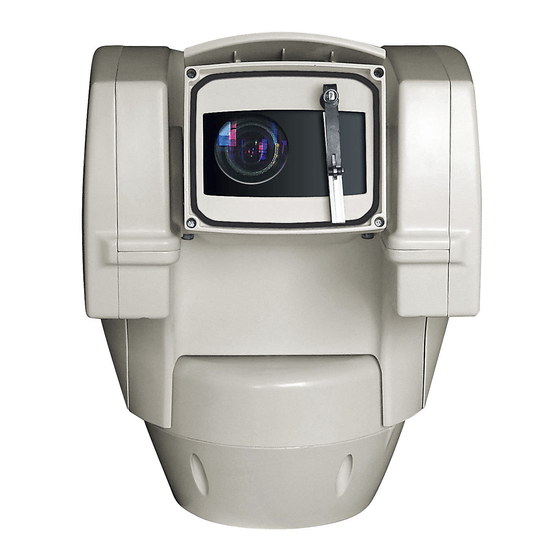
CE markings. designation The renowned outdoor PTZ is now available in Full HD 1080p! The ULISSE COMPACT HD is an IP66 FullHD network camera PTZ that delivers excellent high-definition picture quality. The Full HD Day/Night camera incorporates a 20x optical zoom lens and is able to accurately identify specific details of a scene. -
Page 9: Preparing The Product For Use
5.2 Unpacking and contents 5 Preparing the product for 5.2.1 Unpacking When the product is delivered, make sure that the Any change that is not expressly approved package is intact and that there are no signs that it by the manufacturer will invalidate the has been dropped or scratched. -
Page 10: Preparatory Work Before Installation
5.4 Preparatory work before 6 Assembling and installing installation The assembly and installation must be performed only by skilled personnel. 5.4.1 Attaching the support Different types of supports are available (9 This is a Class A product. In a domestic Accessories, page 27). -
Page 11: Fixing The Base To The Support
6.1.2 Fixing the base to the support 6.1.3 Connection of the connector board Use the screws and the washers supplied 6.1.3.1 Board description with the base. BOARD DESCRIPTION After having positioned gasket (01), fasten base (02) on support (03) using screws (04), toothed spring Connector Function washers (05) and the flat washers (06). -
Page 12: Connection Of The Power Supply Line
6.1.3.2 Connection of the power supply line Connect the power supply cables to the J2 terminal as described in the table. Electrical connections must be performed CONNECTION OF THE POWER SUPPLY LINE with the power supply disconnected and the circuit-breaker open. Colour Terminals Power supply 24Vac... -
Page 13: Connection Of The Secondary Connector Board
6.1.4 Connection of the secondary 6.1.4.2 Connection of the alarm inputs connector board In case of free contact alarm make the connection as shown in the figure. 6.1.4.1 Board description The alarm contacts are present on the connector J4. BOARD DESCRIPTION Connector Function Ethernet Connector... -
Page 14: Relay Connection
6.1.4.3 Relay connection 6.1.4.5 Connection of the Ethernet cable The relay can be used for low working Connect the J1 connector of the secondary connector voltages only (up to 30Vac or 60Vdc) and board using a 5E category, or higher, UTP cable ( with a maximum current of 1A. -
Page 15: Fixing The Top Unit
6.2 Hardware configuration 6.1.5 Fixing the top unit Point the self-centering connector (01) of the upper 6.2.1 Opening the configuration door unit. Point the side set (02) so that it faces the frontal vision of the camera. Position the upper part on the Before powering the device it must be configured base in the same direction shown in the figure. -
Page 16: Configuration Of The Dip-Switches
6.2.2 Configuration of the dip-switches 7 Switching on When the dip-switch rocker (SW) is up it The automatic pre-heating (De-Ice) process represents the value 1 (ON) while if it is could be started whenever the device is down it represents the value 0 (OFF). switched on and the air temperature is below 0°C. -
Page 17: Configuration
8 Configuration The Pan & Tilt control interface is displayed if login is successful. The product can be configured using one of the following tools: • Sofware interface: Configuration via the application installed on PC. • Web interface: Configuration via the browser. 8.1 Sofware interface 8.1.1 Minimum system requirements The supplied Pan &... - Page 18 Click Add. The camera will be available in the device list (Camera list) and can be displayed by dragging-and-dropping the icon onto one of the squares not used. Fig. 22 Fig. 20 To display the cameras on different computers, install Assign a name to the camera and to the unit.
-
Page 19: Web Interface
8.2 Web interface A window appears to add the servers to which connect to by pressing the Add button. During the first connection assign an address other than 192.168.10.100. Browsers supported: Microsoft Internet Explorer, Google Chrome, Mozilla Firefox. The first operation in configuring the P&T unit consists in connecting to the web interface. -
Page 20: User Controls
8.2.2 User Controls Focus far/Focus near To control the Pan & Tilt through the browser, select the User Control entry. A new window will open with a virtual keyboard to enter commands. Fig. 30 • Wiper/Washer Fig. 31 • Day: Activate the camera's IR filter. If available, it turns off the LED illuminators. -
Page 21: Device Parameters
8.2.3 Device Parameters 8.2.5 Network Configuration From menu entry Device Parameters it is possible From menu entry Network Configuration it is possible to set the name of the pan & tilt and view other to change the setting of the Pan & Tilt network. It is additional information. -
Page 22: User Configuration
8.2.6 User Configuration • Autoflip: Turn the Pan & Tilt by 180° when the tilt of the Pan & Tilt reaches the end run. It makes it From menu entry User Configuration it is possible easier tracking subjects along corridors or roads. to administer all users that have access to Pan &... -
Page 23: Autopan
8.2.7.1 Autopan 8.2.8 Preset Parameters In the Autopan subsection it is possible to specify the From menu entry Preset Parameters a number of preset autopan start and end.. parameters relative to the presets can be configured: It is possible to set the speed with which the distance •... -
Page 24: Digital I/O
8.2.10 Digital I/O 8.2.11 Washer In the Digital I/O tab it is possible to configure the The Pan & Tilt wash pump is configured in the Washer digital channels available in Pan & Tilt. What follows is tab where it is possible to associate a preset to the a brief description of the configurable parameters for washing operation, set the duration of washing and each digital input. -
Page 25: Encoder Parameters
8.2.12 Encoder Parameters 8.2.13 Camera Parameters The 2 video streams can be configured under The camera integrated in the Pan & Tilt can be the Encoder Parameters menu. The first stream configured under the Camera Parameters menu: is compulsorily compressed with the H.264/AVC •... -
Page 26: Tools
8.2.14 Tools 8.2.15 Factory Default From menu entry Tools it is possible to re-set the To restore the factory settings relative to the network, predefined values for the entire configuration of Pan user access and camera configuration follow this & Tilt or only for a number of specific sections. procedure: This section: •... -
Page 27: Accessories
9.3 Parapet bracket 9 Accessories Parapet bracket with internal cable channel. For further details on configuration and use, refer to the relative manual. 9.1 Washer If the pan & tilt is fitted with a wiper, it can also have an external pump supplying water to clean the glass. Fig. -
Page 28: Instructions For Normal Operation
10 Instructions for normal operation 10.1 Special controls SPECIAL CONTROLS Control Protocol TCAM ONVIF (auxiliary command) Wiper Start Save Preset 85 tt:Wiper|On Wiper Stop Save Preset 86 tt:Wiper|Off Washer Save Preset 87 tt:WashingProcedure|On Night Mode On Save Preset 88 tt:IRLamp|On Night Mode Off Save Preset 89 tt:IRLamp|Off... -
Page 29: Maintaining And Cleaning
Surface dirt should be rinsed away with water and firmware. then the window cleaned with a neutral soap diluted For further information please contact the VIDEOTEC with water, or specific products for spectacle lens service center. cleaning. These should be applied with a soft cloth. -
Page 30: Disposal Of Waste Materials
12 Disposal of waste 13 Troubleshooting materials Ask for assistance from skilled personnel if: • The unit is damaged after being dropped; This symbol mark and recycle system • There is noticeable deterioration in performance are applied only to EU countries and not of the unit. -
Page 31: Technical Data
14.3 Camera 14 Technical data Day/Night Full HD 20x The installation is type TNV-1, do not Image Device: 1/2.8 type Exmor™ CMOS sensor connect it to SELV circuits. Effective Pixels: approx. 2 million In order to reduce the risk of fire, only Minimum Illumination: use cable sizes greater than or equal to •... -
Page 32: Video
14.4 Video 14.6 Network Compression H.264/AVC and MJPEG Connection Ethernet port LAN 10/100T 2 independent video streams Full HD or 4 14.7 Network protocols independent video streams depending on the configuration ONVIF, Profile S Image resolution: from FullHD to 352x240 in 18 steps For device configuration: TCP/IPv4, UDP/IPv4, HTTP, NTP, DHCP, WS-DISCOVERY Selectable frame rate from 1 to 30 images per second... -
Page 33: Technical Drawings
15 Technical drawings The dimensions of the drawings are in millimetres. Fig. 54 ULISSE COMPACT HD. MNVCUCHD_1405_EN... - Page 34 Fig. 55 ULISSE COMPACT HD with LED illuminator. MNVCUCHD_1405_EN...
- Page 36 Tel. +33 2 32094900 - Fax +33 2 32094901 Email: info@videotec.com Email: info.fr@videotec.com Asia Pacific Videotec (HK) Ltd Americas Videotec Security, Inc. Unit C 24 Floor - Gold King Industrial Building 35 Gateway Drive, Suite 100 - Plattsburgh, NY 12901 - U.S.A.
Need help?
Do you have a question about the ULISSE COMPACT HD and is the answer not in the manual?
Questions and answers