
Related Manuals for Videotec MAXIMUS MPX Series


Summary of Contents for Videotec MAXIMUS MPX Series
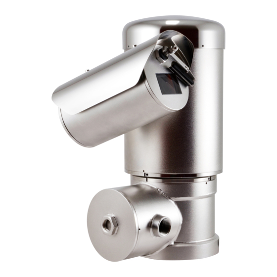
- Page 1 ENGLISH MAXIMUS MPX SERIES (MPXHD) Explosion-proof PTZ camera English - Instruction manual...
-
Page 3: Table Of Contents
Contents E N G L I S H 1 About this manual ........................7 1.1 Typographical conventions ..............................7 Underlined titles .......................... 7 2 Notes on copyright and information on trademarks ............. 7 3 Safety rules..........................7 4 Identification ...........................10 4.1 Product description and type designation .........................10 4.2 Range of use ...................................10 4.3 Specific use conditions ...............................10... - Page 4 7.7 Connection compartment closing ..........................23 8 Switching on ...........................24 9 Configuration ..........................24 9.1 Default IP address.................................24 9.2 Web interface ..................................24 9.2.1 First access to the web pages ................................24 10 Instructions for normal operation ..................25 11 Maintenance .........................25 11.1 Routine maintenance (to be performed on a periodic basis) ................25 11.1.1 Inspecting the cables ..................................25 11.1.2 Replacing the gasket ..................................25 11.2 Extraordinary maintenance (to be done only under particular circumstances) .........26...
- Page 5 MNGCMPXHDC_1916_EN...
- Page 6 MNGCMPXHDC_1916_EN...
-
Page 7: About This Manual
3 Safety rules reliance on the information presented herein. For greater certainty, the use of "manufacturer" in this DANGER! manual means "Videotec S.p.A.". Explosion hazard. Read carefully to avoid danger of explosion. 1.1 Typographical conventions • Installation and maintenance of the appliance... - Page 8 • The equipotential connection is mandatory to • The electrical system to which the unit is avoid the risk of ignition of products installed in connected must be equipped with a 16A max potentially explosive environments. automatic bipolar circuit breaker. The minimum distance between the circuit breaker contacts •...
- Page 9 IEC/EN60079-19. • Contact the manufacturer for information on the • Only use original VIDEOTEC spare parts. Strictly dimensions of the explosion proof joint. adhere to the maintenance instructions attached to each replacement kit.
-
Page 10: Identification
(dissipated power, Watt) and the ambient The MAXIMUS MPX series is equipped with a NPT or temperature. metric cables entry according to the model. The features are specified for each model in its The MAXIMUS MPX series has an IP66/IP68/ specific chapters. -
Page 11: Product Marking
4.7 Product marking Fig. 1 Manufacturer’s name and address. ATEX marking. The Class temperature depends on the electronics installed inside and the Model. ambient temperature. The serial number consists in 12 numeric 10. Marking IECEX. The Class temperature depends characters, the second and third digits on the electronics installed inside and the define the last two numbers of the year of ambient temperature. -
Page 12: For Ul/Csa Standard Reference Only
4.8 For UL/CSA standard reference only. The flameproof joints are not intended to be repaired. CAUTION! Hazardous moving parts. Keep fingers and other body parts away. The appliance includes moving parts. Make sure that the unit is positioned where it is inaccessible under normal operating conditions. - Page 13 Fig. 4 Manufacturer’s name and address. Ambient temperature (-40°C ≤ Ta ≤+TX°C, -40°C ≤ Ta ≤ TX°C or TX°C, -40°C ≤ Ta ≤ TX°C or TX°C or Model. TX°C). The serial number consists in 12 numeric T Class (Tx or Tx...Tx). characters, the second and third digits define the last two numbers of the year of Maximum surface temperature (Tx°C or Tx°C...
-
Page 14: Versions
5 Versions 5.1 Day/Night camera MAXIMUS MPX SERIES2 - CONFIGURATION OPTIONS Voltage Camera Temperature class and am- bient temperature MPXHD 230Vac Avigilon™ Day/Night 30X A T6...T5 -40°C/+55°C or +70°C zoom, Full HD camera 24Vac 120Vac Tab. 2 MAXIMUS MPX SERIES2 - CERTIFICATIONS AND MARKINGS Part number Certification Marking... -
Page 15: Preparing The Product For Use
6 Preparing the product for 6.4 Preparatory work before installation It is possible to install the unit with several brackets. Before carrying out any type of We strongly recommend using only approved intervention, read the "Safety rules" brackets and accessories during installation. chapter carefully in the product manual. -
Page 16: Fixing To Parapet Or Ceiling Mount
6.4.2 Fixing to parapet or ceiling mount 6.4.3 Bracket mounting Fix the adaptor (01) to the bottom of the unit using The bracket can be fixed to the vertical wall. Use the 4 flat countersunk screws (02) with hexagonal screws and wall fixing devices that can bear at least socket M10x20mm in stainless steel (A4 class 70) four times the weight of the unit. -
Page 17: Fastening With Corner Adaptor Module Or Pole
6.4.4 Fastening with corner adaptor 6.4.5 Sunshield mounting module or pole Remove the protective film before the To install the product on the corner adaptor module sunshield installation (if present). or pole, first of all fasten the support bracket. Fix the sunshield to the housing using the screws and washers screwed into the upper body of the housing. -
Page 18: Installation
Remove the VIDEOTEC strongly recommend to test the device security grub screw before unscrewing the configuration and performance before putting it in threaded cover. -
Page 19: Connector Board Description
(03), as Tab. 4 indicated in the figure. If using the VIDEOTEC multipolar cable and RJ45 a fibre optic cable, you are advised to use the left cables input (03) for the multipolar cable and the right cables input (04) for the fibre optic. -
Page 20: Connecting Alarms, Remote Reset And Relays
7.5 Connecting alarms, remote CONNECTION OF THE POWER SUPPLY LINE reset and relays Colour Terminals Power supply 24Vac All signal cables must be grouped together Defined by the installer N (Neutral) by means of a cable tie. Defined by the installer L (Phase) Yellow/Green CONNECTION OF THE ALARM INPUTS AND RELAYS... -
Page 21: Installations According To Ul/Csa Standards
7.5.1 Installations according to UL/CSA standards Pay attention not to damage the conductors and the boards. For installations according to UL/CSA standards, the cables for Ethernet, reset alarms, relays and fibre optics should be inserted in the right cables entry as indicated in the following figure (Fig. -
Page 22: Connecting An Alarm With Dry Contact
100Mbps. Check the settings of the switch to which the product is connected. VIDEOTEC has tested various types of SFP modules. For further information please contact the VIDEOTEC service center. Insert the SFP module (not supplied) in the SFP slot ( 7.3 Connector board description, page 19). -
Page 23: Connection Compartment Closing
The device could be no longer safe for the installation on a potentially explosive atmosphere. In this case contact VIDEOTEC technical support. Before closing the cover, check the O-ring gasket is intact. If the gasket is damaged, replace it with the one supplied (11.1.2 Replacing the gasket, page 25). -
Page 24: Switching On
8 Switching on 9 Configuration 9.1 Default IP address Before carrying out any type of intervention, read the "Safety rules" chapter carefully in the product manual. The unit is configured to obtain an IP address from a DHCP server. The automatic pre-heating (De-Ice) process The IP address acquired via DHCP is visible in the could be started whenever the device is DHCP server log file. -
Page 25: Instructions For Normal Operation
Before carrying out any type of chapter carefully in the product manual. intervention, read the "Safety rules" When contacting VIDEOTEC for assistance please chapter carefully in the product manual. provide the serial number and the identification code of the model. -
Page 26: Extraordinary Maintenance (To Be Done Only Under Particular Circumstances)
11.2 Extraordinary maintenance 11.2.3 Factory Default (to be done only under particular If the access password is no longer available, follow the procedure to reset to circumstances) default factory settings. 11.2.1 Fuse replacement To restore the factory settings relative to the network, If necessary, replace the fuses illustrated in figure (7.3 user access and camera configuration follow this Connector board description, page 19). -
Page 27: Cleaning
12 Cleaning 14 Troubleshooting Before carrying out any type of Before carrying out any type of intervention, read the "Safety rules" intervention, read the "Safety rules" chapter carefully in the product manual. chapter carefully in the product manual. Frequency will depend on the type of Contact an authorized support centre if the environment in which the product is used. -
Page 28: Technical Data
• Supply voltage: 3.3V Dynamic positioning control system • Standard: compliant MSA 15.2 Mechanical The SFP module (not supplied by VIDEOTEC) must meet the following requirements: Cable inputs: 2 x 3/4" NPT • Laser: Class 1, complies with EN60825-1 Zero backlash •... -
Page 29: Day/Night Cameras
15.7 Day/Night cameras 15.9 Certifications Resolution: Full HD 1080p (1920x1080pixel) Electrical safety (CE): EN60950-1, IEC60950-1, EN62368-1, IEC62368-1 Image Sensor: 1/2.8" Progressive Scan CMOS Electromagnetic compatibility (CE): EN50130-4, Focal length: from 4.3mm (wide) up to 129mm (tele) EN55032 (Class A), EN61000-6-4, EN61000-3-2, Zoom: 30x EN61000-3-3 Max Aperture: F1.6... -
Page 30: Technical Drawings
Email: info@videotec.com Tel. +33 1 60491816 - Fax +33 1 69284736 Email: info.fr@videotec.com Asia Pacific Videotec (HK) Ltd Americas Videotec Security, Inc. Flat 8, 19/F. On Dak Industrial Building, No. 2-6 Wah Sing Street Gateway Industrial Park, 35 Gateway Drive, Suite 100 Kwai Chung, New Territories - Hong Kong Plattsburgh, NY 12901 - U.S.A.
Need help?
Do you have a question about the MAXIMUS MPX Series and is the answer not in the manual?
Questions and answers