Table of Contents
Advertisement
Available languages
Available languages
Quick Links
Advertisement
Chapters
Table of Contents

Related Manuals for Videotec Ulisse Evo


Summary of Contents for Videotec Ulisse Evo
- Page 1 ENGLISH ULISSE EVO (UE), ULISSE EVO THERMAL (UET) PTZ camera with high performance and extreme reliability English - Instruction manual Italiano - Manuale di istruzioni Français - Manuel d’instructions Deutsch - Bedienungsanleitung Русский - Руководство по эксплуатации...
- Page 3 ENGLISH ULISSE EVO (UE), ULISSE EVO THERMAL (UET) PTZ camera with high performance and extreme reliability English - Instruction manual...
-
Page 5: Table Of Contents
Contents E N G L I S H 1 About this manual ........................5 1.1 Typographical conventions ..............................5 2 Notes on copyright and information on trademarks ............. 5 3 Safety rules..........................5 4 Identification ..........................8 4.1 Product Overview................................... 8 4.2 Product marking .................................. - Page 6 9.1 Default IP address.................................24 9.2 Web interface ..................................24 9.2.1 First access to the web pages ................................24 10 Accessories and Supports ....................24 10.1 LED illuminator ...................................24 10.2 Washer....................................25 10.3 Power supply ..................................25 10.4 Wall mount bracket ................................26 10.5 Parapet bracket ...................................26 10.6 Parapet bracket with quick connectors ........................26 10.7 Corner adaptor..................................26 10.8 Pole mount adaptor ................................27...
-
Page 7: About This Manual
1 About this manual 3 Safety rules Read all the documentation supplied carefully before CAUTION! Hazardous moving parts. Keep installing and using this product. Keep the manual in fingers and other body parts away. a convenient place for future reference. CAUTION! Device installation and 1.1 Typographical conventions maintaining must be performed by... - Page 8 • The manufacturer declines all responsibility • Before proceeding with installation, check the for any damage caused by an improper use supplied material to make sure it corresponds of the appliances mentioned in this manual. to the order specification by examining the Furthermore, the manufacturer reserves the right identification labels (4.2 Product marking, page 8).
- Page 9 • This is a Class A product. In a domestic • Do not use the appliance in the presence of environment this product may cause radio inflammable substances. interference. In this case the user may be required • Do not allow children or unauthorised people to to take adequate measures.
-
Page 10: Identification
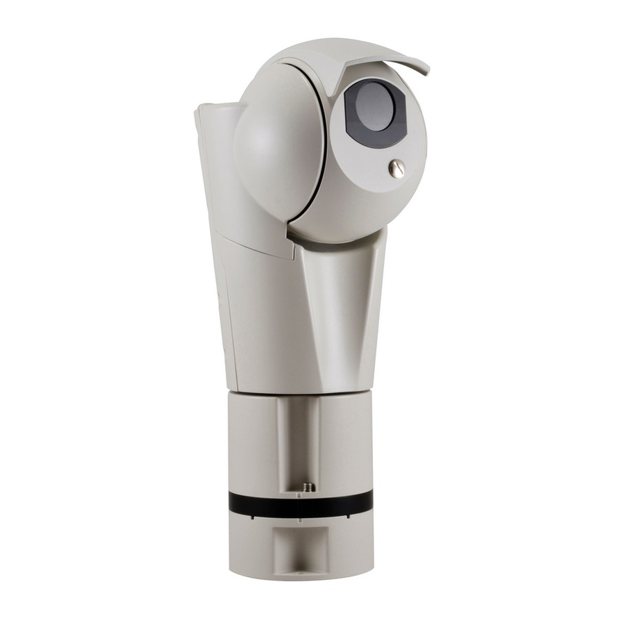
4 Identification 4.2 Product marking 4.1 Product Overview The product has a label applied in compliance with CE marking. The product consists of 3 parts: Sunshield. Body. Base. Fig. 2 The label shows: • Model identification code. • Supply voltage (Volt). •... -
Page 11: Versions
5 Versions 5.3 Intelligent video analysis If the sixth character of the product code is "V", it 5.1 Day/Night FULL HD 30x Super means Videotec technology is present for intelligent low-light camera video analysis. (4.2 Product marking, page 8). 5.4 Thermal camera If the fourth character of the product code is the value "1", it means the Day/Night FULL HD 30x Super... -
Page 12: Preparing The Product For Use
6 Preparing the product for 6.2 Unpacking When the product is delivered, make sure that the package is intact and that there are no signs that it has been dropped or scratched. Any change that is not expressly approved by the manufacturer will invalidate the If there are obvious signs of damage, contact the guarantee. -
Page 13: Installation Mode
6.5 Installation mode The product can be installed in various modes using the supports and various adaptors available, meeting every installation requirement. 6.5.1 Installation with internal cable passage This installation mode allows cable passage inside the mounting brackets. Fig. 5 MNVCEVO_1947_EN... -
Page 14: Installation With Internal Cable Passage With Product Overturned
6.5.2 Installation with internal cable passage with product overturned CAUTION! Always secure the product with the safety chain (6.6.6 Fastening of the safety coupling, page 17). This installation mode allows cable passage inside the mounting brackets. In the event of installation of the product overturned, the sunshield must be assembled as illustrated in the relevant chapter (6.6.5 Sunshield mounting, page 17) and enable the Ceiling Assembly mode using the web interface. -
Page 15: Installation With Quick Connectors
6.5.3 Installation with quick connectors This installation mode thanks to the quick connectors allows easy and fast replacement of the unit in the event of intervention on site. Fig. 7 MNVCEVO_1947_EN... -
Page 16: Installation With Quick Connectors With Product Overturned
6.5.4 Installation with quick connectors with product overturned CAUTION! Always secure the product with the safety chain (6.6.6 Fastening of the safety coupling, page 17). This installation mode thanks to the quick connectors allows easy and fast replacement of the unit in the event of intervention on site. -
Page 17: Preparatory Work Before Installation
6.6 Preparatory work before 6.6.2 Mounting the bracket installation Take special care when attaching and fastening down the apparatus. If the 6.6.1 Opening the base of the product equipment must be fastened to a concrete surface, plugs must be used with a To avoid scratching the product with the hexagonal minimum traction force of 300dN each. -
Page 18: Cables Management
6.6.3 Cables management The cables must be adequately fastened to the structure to avoid the excessive weight causes accidental removal. You must use cables suited to the type of installation. Insert the cables into the cable glands. The M16 cable glands are suitable for cables with a diameter between 4.5mm (0.18in) and 10mm (0.39in). -
Page 19: Fixing The Base To The Support
6.6.4 Fixing the base to the support 6.6.6 Fastening of the safety coupling For further details on configuration and Take special care when attaching and use, refer to the manual of the relevant fastening down the apparatus. If the accessory or support. equipment must be fastened to a concrete surface, plugs must be used with a 6.6.5 Sunshield mounting... -
Page 20: Installation
7 Installation 7.1 Connection of the connector board Never, under any circumstances, make any changes or connections that are not 7.1.1 Connector board description shown in this handbook. Failure to follow The ground cable must always be the connection instructions that are given connected to the relevant terminal (GND, in the handbook may create serious safety 7.1.1 Connector board description, page ... -
Page 21: Connection Of The Power Supply Line (24Vac/24Vdc)
7.1.2 Connection of the power supply line (24Vac/24Vdc) Electrical connections must be performed with the power supply disconnected and the circuit-breaker open. When commencing installation make sure that the specifications for the power supply for the installation correspond with those required by the device. -
Page 22: Alarm And Relay Connections
7.1.3 Alarm and relay connections Nominal section of the cables used: consult the technical data in the relevant chapter ( 16.4 Electrical, page 30). Maximum relay voltage and current: consult the technical data in the relevant chapter (16.4 Electrical, page 30). Connect the digital I/O cable to the relative connector (J6, 7.1.1 Connector board description, page 18). -
Page 23: Connection Of The Ethernet Cable
7.1.4 Connection of the Ethernet cable 7.1.4.1 PoE 90W power supply The product can be powered in PoE 90W using our Use of Ethernet cables with the following power injector (10.3 Power supply, page 25). characteristics is highly recommended: If the product is powered by two sources of power •... -
Page 24: Installation Of The Upper Body
7.2 Installation of the upper body Place the unit body on the base aligning the reference marks. Be especially careful not to damage internal components during installation. Installation of the upper body must take place with the base not powered. Check the LED indicated in the figure is off (Fig. -
Page 25: Switching On
8 Switching on The automatic pre-heating (De-Ice) process could be started whenever the device is switched on and the ambient temperature is below 0°C (+32°F). The procedure is necessary to guarantee correct operation of the devices even at low temperatures. The duration ranges depending on environmental conditions (from 60 minutes up to 120 minutes). -
Page 26: Configuration
Fig. 26 UEIxxx. On first access, the Home page will be displayed. For the configuration of the web interface, please refer to the instruction manual relating to the installed firmware version, available on the product web page on www.videotec.com. MNVCEVO_1947_EN... -
Page 27: Washer
10.2 Washer The product can be equipped with an external pump that provides water to clean the glass. Fig. 29 UPTIRPS120UL (120Vac-24Vac). Fig. 30 OHEP90INJ, OHEP90INJUS. Fig. 27 Nozzle supplied with wash system. 10.3 Power supply The PTZ camera can be powered using the external power supply unit. -
Page 28: Wall Mount Bracket
10.4 Wall mount bracket 10.6 Parapet bracket with quick connectors Wall bracket with internal cable channel. There are two quick connectors, connector RJ45 for Ethernet and a multi-polar connector for power supply and I/O. Based on the version of the support, the multi-polar connector can have 4 poles with a screw terminal or 7 poles to weld. -
Page 29: Pole Mount Adaptor
Special controls are implemented using the auxiliary commands of the ONVIF protocol. • Through PTZ Assistant software (the PTZ Assistant software is available to download on the product web page of our website www.videotec.com). Fig. 36 UEAP. 10.9 Counter-plate The counter-plate can be used for railing, wall or ceiling assembly, also for channel applications. -
Page 30: Maintenance
12 Maintenance • Assemble the upper body (7.2 Installation of the upper body, page 22). • Power the unit. Wait for 2 minutes. CAUTION! Device installation and maintaining must be performed by • Disconnect the power supply to the unit. specialist technical staff only. •... -
Page 31: Cleaning
The European Directive 2012/19/EU on Waste SOLUTION Contact the technical assistance Electrical and Electronic Equipment (WEEE) mandates service (VIDEOTEC). that these devices should not be disposed of in the normal flow of municipal solid waste, but they should PROBLEM The shooting area do not... -
Page 32: Technical Data
16 Technical data 16.3 Windows for camera Glass window CAUTION! TNV-1 installation type. The • Thick: 6mm (0.24in) installation is type TNV-1, do not connect it to SELV circuits. Germanium window • Thick: 1.5mm (0,06in) CAUTION! In order to reduce the risk of fire, •... -
Page 33: Cybersecurity
16.6 Cybersecurity 16.8 Video for Thermal camera Digitally signed firmware Video encoder Password restricted access (HTTP digest) • Communication protocol: ONVIF, Profile Q, Profile S and Profile T, ONVIF Thermal Service Support of various user access levels • Device configuration: TCP/IPv4-IPv6, UDP/IPv4- Control of accesses IEEE 802.1X IPv6, HTTP, HTTPS, NTP, DHCP, WSDISCOVERY, HTTPS cryptography using TLS1.0, TLS1.1, TLS1.2 and... -
Page 34: Day/Night Cameras
16.9 Day/Night cameras SONY FCB-EV7520 Day/Night Full HD 30x Resolution: Full HD 1080p (1920x1080) Day/Night Full HD 30x DeLux Image Device: 1/2.8" Exmor™ R CMOS sensor Resolution: Full HD 1080p (1920x1080pixel) Effective Pixels: approx. 2.13 Megapixels Image Device: 1/2.8" Exmor™ R CMOS sensor Minimum Illumination: Effective Pixels: approx. -
Page 35: Thermal Cameras
16.10 Thermal Cameras THERMAL CAMERAS (RESOLUTION 336X256) Lens 9mm Lens 13mm Lens 19mm Lens 25mm Lens 35mm Image Device Uncooled VOx Uncooled VOx Uncooled VOx Uncooled VOx Uncooled VOx microbolo- microbolo- microbolo- microbolo- microbolo- meter meter meter meter meter Interpolated resolution 720x480 720x480 720x480... - Page 36 THERMAL CAMERAS (RESOLUTION 640X512) Lens 9mm Lens 13mm Lens 19mm Lens 25mm Lens 35mm Image Device Uncooled VOx Uncooled VOx Uncooled VOx Uncooled VOx Uncooled VOx microbolo- microbolo- microbolo- microbolo- microbolo- meter meter meter meter meter Interpolated resolution 720x480 720x480 720x480 720x480 720x480...
-
Page 37: Illuminators
ENV5) (R2008) par. 2.1.5.1, test profile fig. 2-1 (from -34°C (-29.2°F) to +74°C (165.2°F)) (not valid for Electromagnetic compatibility: EN60945 versions with integrated video analysis, VIDEOTEC Salty fog resistance: EN60068-2-52 Analytics) • De-icing function intervention: from -40°C (-40°F) up to -10°C (14°F) Wind resistance •... -
Page 38: Technical Drawings
17 Technical drawings The indicated measurements are expressed in millimetres. Fig. 40 ULISSE EVO. Fig. 41 ULISSE EVO THERMAL. MNVCEVO_1947_EN... - Page 39 Fig. 42 ULISSE EVO with LED illuminator. MNVCEVO_1947_EN...
- Page 40 Email: info@videotec.com Tel. +33 1 60491816 - Fax +33 1 69284736 Email: info.fr@videotec.com Asia Pacific Videotec (HK) Ltd Americas Videotec Security, Inc. Flat 8, 19/F. On Dak Industrial Building, No. 2-6 Wah Sing Street Gateway Industrial Park, 35 Gateway Drive, Suite 100 Kwai Chung, New Territories - Hong Kong Plattsburgh, NY 12901 - U.S.A.
- Page 41 ITALIANO ULISSE EVO (UE), ULISSE EVO THERMAL (UET) Telecamera PTZ con prestazioni elevate ed estrema affidabilità Italiano - Manuale di istruzioni...
- Page 43 Sommario I T A L I A N O 1 Informazioni sul presente manuale ..................5 1.1 Convenzioni tipografiche ..............................5 2 Note sul copyright e informazioni sui marchi commerciali ........... 5 3 Norme di sicurezza ........................5 4 Identificazione .......................... 8 4.1 Panoramica del prodotto ..............................
- Page 44 9.1 Indirizzo IP di default................................24 9.2 Interfaccia web ..................................24 9.2.1 Primo accesso alle pagine web .................................24 10 Accessori e supporti ......................24 10.1 Illuminatore a LED ................................24 10.2 Impianto di lavaggio .................................25 10.3 Alimentatore ..................................25 10.4 Supporto da parete ................................26 10.5 Supporto da parapetto ..............................26 10.6 Supporto da parapetto con connettori ad innesto rapido .................26 10.7 Adattatore ad angolo ...............................26 10.8 Collare da palo ..................................27...
-
Page 45: Informazioni Sul Presente Manuale
1 Informazioni sul presente 3 Norme di sicurezza manuale ATTENZIONE! Parti mobili pericolose. Non avvicinare dita e altre parti del corpo. Prima di installare e utilizzare questo prodotto, leggere attentamente tutta la documentazione ATTENZIONE! L'installazione e la fornita. Tenere il manuale a portata di mano per manutenzione del dispositivo devono consultazioni successive. - Page 46 • Il produttore declina ogni responsabilità per • Prima di procedere con l'installazione, controllare eventuali danni derivanti da un uso improprio che il materiale fornito corrisponda alle specifiche delle apparecchiature menzionate in questo richieste esaminando le etichette di marcatura (4.2 manuale.
- Page 47 • Questo è un prodotto di Classe A. In un ambiente • Non utilizzare l’apparecchio in presenza di residenziale questo prodotto può provocare sostanze infiammabili. radiodisturbi. In questo caso può essere richiesto • Non permettere l’uso dell’apparecchio a bambini o all'utilizzatore di prendere misure adeguate.
-
Page 48: Identificazione
4 Identificazione 4.2 Marcatura del prodotto 4.1 Panoramica del prodotto Sul prodotto è applicata una etichetta conforme alla marcatura CE. Il prodotto è composto da 3 parti: Tettuccio. Corpo. Base. Fig. 2 L'etichetta riporta: • Codice di identificazione del modello. •... -
Page 49: Versioni
5 Versioni 5.3 Analisi intelligente del video Se il sesto carattere del codice prodotto è "V" significa 5.1 Telecamera Day/Night FULL che è presente la tecnologia Videotec per l'analisi HD 30x Super low-light intelligente del video. (4.2 Marcatura del prodotto, pagina 8). -
Page 50: Preparazione Del Prodotto Per L'utilizzo
6 Preparazione del prodotto 6.2 Disimballaggio per l'utilizzo Alla consegna del prodotto verificare che l'imballo sia integro e non presenti segni evidenti di cadute o abrasioni. Qualsiasi intervento non espressamente approvato dal costruttore fa decadere la In caso di danni evidenti all'imballo contattare garanzia. -
Page 51: Modalità D'installazione
6.5 Modalità d'installazione Il prodotto può essere installato in diversi modi utilizzando i supporti e i diversi adattatori disponibili, soddisfando ogni esigenza d'installazione. 6.5.1 Installazione con passaggio interno dei cavi Questa modalità di installazione permette il passaggio dei cavi all'interno delle staffe di supporto. Fig. -
Page 52: Installazione Con Passaggio Interno Dei Cavi Con Prodotto Capovolto
6.5.2 Installazione con passaggio interno dei cavi con prodotto capovolto ATTENZIONE! Assicurare sempre il prodotto con la catena di sicurezza (6.6.6 Fissaggio dell'aggancio di sicurezza, pagina 17). Questa modalità di installazione permette il passaggio dei cavi all'interno delle staffe di supporto. Nel caso di installazione del prodotto capovolto è... -
Page 53: Installazione Con Connettori A Innesto Rapido
6.5.3 Installazione con connettori a innesto rapido Questa modalità di installazione, grazie ai connettori ad innesto rapido, consente la facile e veloce sostituzione dell'unità in caso di intervento in loco. Fig. 7 MNVCEVO_1947_IT... -
Page 54: Installazione Con Connettori A Innesto Rapido Con Prodotto Capovolto
6.5.4 Installazione con connettori a innesto rapido con prodotto capovolto ATTENZIONE! Assicurare sempre il prodotto con la catena di sicurezza (6.6.6 Fissaggio dell'aggancio di sicurezza, pagina 17). Questa modalità di installazione, grazie ai connettori ad innesto rapido, consente la facile e veloce sostituzione dell'unità... -
Page 55: Lavoro Preparatorio Prima Dell'installazione
6.6 Lavoro preparatorio prima 6.6.2 Fissaggio del supporto dell’installazione Porre particolare attenzione ai sistemi di fissaggio dell'apparecchiatura. Se 6.6.1 Apertura della base del prodotto l'apparecchiatura deve essere fissata ad una superficie di calcestruzzo bisogna utilizzare Per evitare di graffiare il prodotto con la chiave tasselli con forza di trazione minima pari esagonale, allineare il corpo del prodotto con la vite a 300dN cadauno. -
Page 56: Passaggio Cavi
6.6.3 Passaggio cavi I cavi devono essere opportunamente fissati alla struttura per evitare che l'eccessivo peso ne comporti lo sfilamento accidentale. I cavi utilizzati devono essere conformi al tipo di installazione. Introdurre i cavi all’interno dei pressacavi. I pressacavi M16 sono adatti per cavi con diametro compreso tra 4.5mm e 10mm. -
Page 57: Fissaggio Della Base Al Supporto
6.6.4 Fissaggio della base al supporto 6.6.6 Fissaggio dell'aggancio di sicurezza Per ulteriori dettagli sulla configurazione e l’utilizzo fare riferimento al manuale del Porre particolare attenzione ai sistemi relativo accessorio o supporto. di fissaggio dell'apparecchiatura. Se l'apparecchiatura deve essere fissata ad una 6.6.5 Fissaggio del tettuccio superficie di calcestruzzo bisogna utilizzare È... -
Page 58: Installazione
7 Installazione 7.1 Collegamento della scheda connettori Non effettuare per nessun motivo alterazioni o collegamenti non previsti 7.1.1 Descrizione della scheda in questo manuale. Il mancato rispetto connettori delle indicazioni fornite nel manuale in merito ai collegamenti può portare a gravi Il cavo di terra deve sempre essere collegato pericoli per la sicurezza del personale e al relativo morsetto (GND, 7.1.1 Descrizione... -
Page 59: Collegamento Della Linea Di Alimentazione (24Vac/24Vdc)
7.1.2 Collegamento della linea di alimentazione (24Vac/24Vdc) Eseguire le connessioni elettriche in assenza di alimentazione e con dispositivo di sezionamento aperto. All’atto dell’installazione controllare che le caratteristiche di alimentazione fornite dall’impianto corrispondano a quelle richieste dal dispositivo. Non alimentare il prodotto mediante auto trasformatori. -
Page 60: Collegamento Degli Allarmi E Dei Relè
7.1.3 Collegamento degli allarmi e dei relè Sezione nominale dei cavi utilizzabili: consultare i dati tecnici presenti nel relativo capitolo (16.4 Elettrico, pagina 30). Tensione e corrente massima dei relè: consultare i dati tecnici presenti nel relativo capitolo (16.4 Elettrico, pagina 30). Collegare il cavo degli I/O digitali al relativo connettore (J6, 7.1.1 Descrizione della scheda connettori, pagina 18). -
Page 61: Collegamento Del Cavo Di Rete Ethernet
7.1.4 Collegamento del cavo di rete 7.1.4.1 Alimentazione in PoE 90W Ethernet Il prodotto può essere alimentato in PoE 90W tramite il nostro power injector (10.3 Alimentatore, pagina Si raccomanda l'utilizzo di cavi Ethernet con le 25). seguenti caratteristiche: Se il prodotto viene alimentato da due fonti di •... -
Page 62: Installazione Del Corpo Superiore
7.2 Installazione del corpo Posizionare il corpo dell'unità sulla base allineando le tacche di riferimento. Prestare particolare attenzione superiore a non danneggiare i componenti interni durante l'installazione. L'installazione del corpo superiore deve essere fatta con la base non alimentata. Verificare che il LED indicato in figura sia spento (Fig. 22, pagina 22). -
Page 63: Accensione
8 Accensione La procedura di preriscaldamento automatico (De-Ice) si potrebbe attivare tutte le volte che il dispositivo viene acceso ad una temperatura ambiente inferiore a 0°C. La procedura serve a garantire la corretta funzionalità del dispositivo anche alle basse temperature. La durata varia a seconda delle condizioni climatiche (da 60 minuti fino a 120 minuti). -
Page 64: Configurazione
Al primo accesso sarà visualizzata la pagina di Home. Per la configurazione dell'interfaccia web consultare il manuale relativo alla versione firmware installata, disponibile nella pagina web del prodotto sul nostro sito www.videotec.com. MNVCEVO_1947_IT... -
Page 65: Impianto Di Lavaggio
10.2 Impianto di lavaggio Il prodotto può essere dotato di una pompa esterna che fornisce acqua per la pulizia del vetro. Fig. 29 UPTIRPS120UL (120Vac-24Vac). Fig. 30 OHEP90INJ, OHEP90INJUS. Fig. 27 Ugello in dotazione con l'impianto di lavaggio. 10.3 Alimentatore La telecamera PTZ può... -
Page 66: Supporto Da Parete
10.4 Supporto da parete 10.6 Supporto da parapetto con connettori ad innesto rapido Supporto per montaggio a parete con passaggio interno cavi. I connettori ad innesto rapido sono due, un connettore RJ45 per l'ethernet e un connettore multipolare per alimentazione e I/O. In base alla versione del supporto il connettore multipolare può... -
Page 67: Collare Da Palo
ONVIF. • Tramite il software PTZ Assistant (il software PTZ Assistant è disponibile per il download nella pagina web del prodotto sul nostro sito www. videotec.com). Fig. 36 UEAP. 10.9 Contropiastra La contropiastra può essere utilizzata per il montaggio a parapetto, a parete o a soffitto, anche per applicazioni con canaletta. -
Page 68: Manutenzione
12 Manutenzione • Montare il corpo superiore (7.2 Installazione del corpo superiore, pagina 22). • Alimentare l'unità. Attendere 2 minuti. ATTENZIONE! L'installazione e la manutenzione del dispositivo devono • Togliere alimentazione all'unità. essere eseguite solo da personale tecnico • Aprire la base del prodotto (6.6.1 Apertura della specializzato. -
Page 69: Pulizia
Possibile guasto del fusibile F3. La Direttiva Europea 2012/19/UE sui Rifiuti di SOLUZIONE Contattare l'assistenza tecnica Apparecchiature Elettriche ed Elettroniche (RAEE) (VIDEOTEC). prevede che questi apparecchi non debbano essere smaltiti nel normale flusso dei rifiuti solidi urbani, ma PROBLEMA L'area ripresa non corrisponde... -
Page 70: Dati Tecnici
16 Dati tecnici 16.3 Finestre per telecamera Finestra in vetro ATTENZIONE! L'installazione è di tipo TNV-1. • Spessore: 6mm Non collegare a circuiti SELV. Finestra in germanio ATTENZIONE! Per ridurre il rischio di • Spessore: 1.5mm incendio usare solamente cavi certificati •... -
Page 71: Cybersecurity
16.6 Cybersecurity 16.8 Video per telecamera Termica Firmware firmato digitalmente Restrizione dell'accesso mediante password (HTTP Encoder video digest) • Protocollo di comunicazione: ONVIF, Profilo Q, Supporto di diversi livelli di accesso utente Profilo S e Profilo T, ONVIF Thermal Service Controllo degli accessi IEEE 802.1X •... -
Page 72: Telecamere Day/Night
16.9 Telecamere Day/Night SONY FCB-EV7520 Day/Night Full HD 30x Risoluzione: Full HD 1080p (1920x1080) Day/Night Full HD 30x DeLux Sensore di immagine: 1/2.8" Exmor™ R CMOS sensor Risoluzione: Full HD 1080p (1920x1080pixel) Pixel Effettivi: appross. 2.13 Megapixel Sensore di immagine: 1/2.8" Exmor™ R CMOS sensor Illuminazione Minima: Pixel Effettivi: appross. -
Page 73: Telecamere Termiche
16.10 Telecamere Termiche TELECAMERE TERMICHE (RISOLUZIONE 336X256) Obiettivo Obiettivo Obiettivo Obiettivo Obiettivo 13mm 19mm 25mm 35mm Sensore di immagine Microbolo- Microbolo- Microbolo- Microbolo- Microbolo- metro non metro non metro non metro non metro non raffreddato raffreddato raffreddato raffreddato raffreddato (VOx) (VOx) (VOx) (VOx) - Page 74 TELECAMERE TERMICHE (RISOLUZIONE 640X512) Obiettivo Obiettivo Obiettivo Obiettivo Obiettivo 13mm 19mm 25mm 35mm Sensore di immagine Microbolo- Microbolo- Microbolo- Microbolo- Microbolo- metro non metro non metro non metro non metro non raffreddato raffreddato raffreddato raffreddato raffreddato (VOx) (VOx) (VOx) (VOx) (VOx) Risoluzione interpolata 720x480...
-
Page 75: Illuminatori
(R2008) par. 2.1.5.1, profilo di test fig. 2-1 (da -34°C • Test Specification Number 1 (ENV1, ENV2, ENV3, fino a +74°C) (non valido per versioni con video ENV5) analisi integrata, VIDEOTEC Analytics) Compatibilità elettromagnetica: EN60945 • Intervento della funzione de-icing: da -40°C fino a -10°C... -
Page 76: Disegni Tecnici
17 Disegni tecnici Le misure indicate sono espresse in millimetri. Fig. 40 ULISSE EVO. Fig. 41 ULISSE EVO THERMAL. MNVCEVO_1947_IT... - Page 77 Fig. 42 ULISSE EVO con illuminatore a LED. MNVCEVO_1947_IT...
- Page 78 Email: info@videotec.com Tel. +33 1 60491816 - Fax +33 1 69284736 Email: info.fr@videotec.com Asia Pacific Videotec (HK) Ltd Americas Videotec Security, Inc. Flat 8, 19/F. On Dak Industrial Building, No. 2-6 Wah Sing Street Gateway Industrial Park, 35 Gateway Drive, Suite 100 Kwai Chung, New Territories - Hong Kong Plattsburgh, NY 12901 - U.S.A.
- Page 79 FRANÇAIS ULISSE EVO (UE), ULISSE EVO THERMAL (UET) Caméra PTZ haute performance et fiabilité extrême Français - Manuel d’instructions...
- Page 81 Sommaire F R A N Ç A I S 1 À propos de ce mode d’emploi ....................5 1.1 Conventions typographiques ............................5 2 Notes sur le copyright et informations sur les marques de commerce ........ 5 3 Normes de securité ........................5 4 Identification ..........................
- Page 82 9.1 Adresse IP par défaut ................................24 9.2 Interface web ..................................24 9.2.1 Premier accès aux pages web ................................24 10 Accessoires et supports......................24 10.1 Projecteur à LED .................................24 10.2 Système de lavage ................................25 10.3 Alimentation ..................................25 10.4 Support fixation murale ..............................26 10.5 Support fixation sol ................................26 10.6 Support de parapet avec connecteurs à...
-
Page 83: À Propos De Ce Mode D'emploi
1 À propos de ce mode 3 Normes de securité d’emploi ATTENTION! Parties mobiles dangereux. Ne pas approcher les doigts ou d'autres parties Avant d'installer et d'utiliser ce produit, lire du corps. attentivement toute la documentation fournie. Garder le manuel à portée de main pour des ATTENTION! L’installation et l’entretien consultations successives. - Page 84 • Le fabricant décline toute responsabilité pour les • Avant de procéder à l’installation, contrôler que dommages éventuels dus à une utilisation non le matériel fourni correspond à la commande appropriée des appareils mentionnés dans ce et examiner les étiquettes de marquage (4.2 manuel.
- Page 85 • Ce produit appartient à la Classe A. Dans un • Ne pas utiliser l'appareil en présence de substances milieu résidentiel ce produit peut être la cause de inflammables. radioperturbations. Dans ce cas il est préferable de • Ne pas laisser l'appareil à portée des enfants ou de prendre des mésures appropritées.
-
Page 86: Identification
4 Identification 4.2 Marquage du produit 4.1 Vue d’ensemble du produit Une étiquette conforme au marquage CE est apposée sur le produit. Le produit se compose de 3 parties: Double toit. Corps. Base. Fig. 2 L'étiquette indique: • Code d'identification du modèle. •... -
Page 87: Versions
5.1 Caméra Jour/Nuit FULL HD Si le sixième caractère du code du produit est « V », 30x Super low-light ceci signifie que la technologie Videotec pour l'analyse intelligente de la vidéo est disponible. (4.2 Si le quatrième caractère du code du produit affiche Marquage du produit, page 8). -
Page 88: Préparation Du Produit En Vue De L'utilisation
6 Préparation du produit en 6.2 Déballage vue de l’utilisation Lors de la livraison du produit, vérifier que l’emballage est en bon état et l’absence de tout signe évident de chute ou d’abrasion. Toute modification non approuvée expressément par le fabricant entraînera En cas de dommages évidents, contacter l’annulation de la garantie. -
Page 89: Modes D'installation
6.5 Modes d'installation Le produit peut être installé de plusieurs façons avec les différents supports et adaptateurs disponibles, pour répondre à chaque exigence d’installation. 6.5.1 Installation avec passage de câble interne Ce mode d'installation permet le passage des câbles à l'intérieur des brides de support. Fig. -
Page 90: Installation Avec Passage Interne Des Câbles Avec Le Produit Inversé
6.5.2 Installation avec passage interne des câbles avec le produit inversé ATTENTION! Sécurisez toujours le produit avec la chaîne de sécurité (6.6.6 Fixation d’accrochage de sécurité, page 17). Ce mode d'installation permet le passage des câbles à l'intérieur des brides de support. En cas d'installation du produit inversé, vous devez installer le toit pare-soleil comme indiqué... -
Page 91: Installation Avec Des Connecteurs À Fixation Rapide
6.5.3 Installation avec des connecteurs à fixation rapide Ce mode d'installation, grâce aux connecteurs à fixation rapide, permet de remplacer facilement et rapidement l'unité en cas d'intervention sur site. Fig. 7 MNVCEVO_1947_FR... -
Page 92: Installation Avec Connecteurs Rapide Avec Produit Inversé
6.5.4 Installation avec connecteurs rapide avec produit inversé ATTENTION! Sécurisez toujours le produit avec la chaîne de sécurité (6.6.6 Fixation d’accrochage de sécurité, page 17). Ce mode d'installation, grâce aux connecteurs à fixation rapide, permet de remplacer facilement et rapidement l'unité en cas d'intervention sur site. En cas d'installation du produit inversé, vous devez installer le toit pare-soleil comme indiqué... -
Page 93: Opérations À Effectuer Avant L'installation
6.6 Opérations à effectuer avant 6.6.2 Fixation du support l’installation Accorder une attention particulière aux systèmes de fixation de l'appareil. Si le 6.6.1 Ouverture de la base du produit dispositif doit être fixé à une surface en béton, utiliser des chevilles avec force de Pour éviter de rayer le produit avec la clé... -
Page 94: Passage Des Câbles
6.6.3 Passage des câbles Les câbles doivent être adéquatement fixés à la structure afin d'éviter que le poids excessif provoque son extraction accidentelle. Les câbles utilisés doivent être conformes au type d'installation. Insérez les câbles dans les presse-étoupes. Les presse-étoupes M16 sont adaptés pour des câbles ayant un diamètre compris entre 4.5mm et 10mm. -
Page 95: Fixage De La Base Au Support
6.6.4 Fixage de la base au support 6.6.6 Fixation d’accrochage de sécurité Pour plus d'informations sur la Accorder une attention particulière aux configuration et l'utilisation, reportez-vous systèmes de fixation de l'appareil. Si le au manuel de l'accessoire ou du support dispositif doit être fixé... -
Page 96: Installation
7 Installation 7.1 Connexion de la carte de connexion Ne procéder sous aucun prétexte à des modifications ou des connexions non 7.1.1 Description de la carte de prévues dans ce manuel. L’utilisation connexion d’appareils inadéquats peut comporter des risques sérieux pour les appareils et la Le câble de terre doit toujours être branché... -
Page 97: Connexion De La Ligne D'alimentation (24Vac/24Vdc)
7.1.2 Connexion de la ligne d'alimentation (24Vac/24Vdc) Il faut effectuer les connexions électriques en absence d'alimentation et lorsque le dispositif de sectionnement ouvert. Contrôler que les sources d'alimentation et les câbles de branchement sont en mesure de supporter la consommation du système. N'alimentez pas le produit avec des autotransformateurs. -
Page 98: Branchement Aux Alarmes Et Aux Relais
7.1.3 Branchement aux alarmes et aux relais Section nominale des câbles utilisés: consultez les caractéristiques techniques figurant au chapitre correspondant (16.4 Électrique, page 30). Tension et courant maximum de relais: consultez les caractéristiques techniques figurant au chapitre correspondant (16.4 Électrique, page 30). Branchez le câble des entrées/sorties numériques au RL2B connecteur correspondant (J6, 7.1.1 Description de la... -
Page 99: Branchement Du Câble De Réseau Ethernet
7.1.4 Branchement du câble de réseau 7.1.4.1 Alimentation en PoE 90W Ethernet Le produit peut être alimenté en PoE 90W via notre injecteur de puissance (10.3 Alimentation, page 25). Nous recommandons l'utilisation de câbles Ethernet Si le produit est alimenté par deux sources d'énergie ayant les caractéristiques suivantes: en même temps (24V et PoE 90W), seule la ligne en •... -
Page 100: Installation Du Haut Du Corps
7.2 Installation du haut du corps Placez le corps de l’appareil sur la base en alignant les encoches de référence. Veillez à ne pas abîmer les composants intérieurs lors de l’installation. La partie supérieure du corps doit être installée quand la base n'est pas alimentée. Vérifiez que la LED indiqué... -
Page 101: Allumage
8 Allumage La procédure de préchauffage automatique (De-Ice) peut être activée chaque fois que le dispositif est mis en fonction à une température ambiante inférieure à 0°C. La procédure permet de garantir un fonctionnement correct du dispositif également à basse température. La durée varie en fonction des conditions climatiques (de 60 minutes jusqu'à... -
Page 102: Configuration
Fig. 26 UEIxxx. indirizzo_ip. La page d'accueil sera affichée au premier accès. Pour la configuration de l'interface web, veuillez vous reporter au manuel d’instruction relatif à la version du firmware installé, disponible sur la page web du produit sur www.videotec.com. MNVCEVO_1947_FR... -
Page 103: Système De Lavage
10.2 Système de lavage Le produit peut être équipé d'une pompe externe qui fournit l'eau pour nettoyer la vitre. Fig. 29 UPTIRPS120UL (120Vac-24Vac). Fig. 30 OHEP90INJ, OHEP90INJUS. Fig. 27 Buse fournie pour l'installation de lavage. 10.3 Alimentation La caméra PTZ peut être alimentée par l'alimentation externe. -
Page 104: Support Fixation Murale
10.4 Support fixation murale 10.6 Support de parapet avec connecteurs à fixation rapide Support mural avec passage interne des câbles. Il y a deux connecteurs à fixation rapide, un connecteur RJ45 pour Ethernet et un connecteur multipolaire pour l'alimentation et les I/O. Selon la version du support, le connecteur multipolaire peut être à... -
Page 105: Collier De Fixation Sur Poteau
Commandes spéciales sont implémentées à l'aide des commandes auxiliaires du protocole ONVIF. • À l'aide du logiciel PTZ Assistant (le logiciel PTZ Assistant peut être téléchargé librement sur la page web du produit, sur notre site www.videotec. com). Fig. 36 UEAP. -
Page 106: Entretien
12 Entretien • Monter le haut du corps (7.2 Installation du haut du corps, page 22). • Allumer l'unité. Attendre 2 minutes. ATTENTION! L’installation et l’entretien du dispositif doivent être effectués • Couper l'alimentation à l'unité. exclusivement par un personnel technique •... -
Page 107: Nettoyage
CAUSE Possible anomalie du fusible F3. l'élimination et le recyclage SOLUTION Consulter l’assistance technique (VIDEOTEC). La Directive Européenne 2012/19/UE sur les déchets d'équipements électriques et électroniques (DEEE) PROBLÈME L'aire filmée ne correspond exige que ces dispositifs ne doivent pas être éliminés pas à... -
Page 108: Données Techniques
16 Données techniques 16.3 Fenêtres pour caméra Fenêtre en verre ATTENTION! L'installation est du type TNV- • Épaisseur: 6mm 1. Ne pas la connecter à des circuits SELV. Fenêtre en germanium ATTENTION! Pour réduire les risques • Épaisseur: 1.5mm d’incendie, utiliser uniquement des câbles •... -
Page 109: Cybersecurity
16.6 Cybersecurity 16.8 Vidéo pour caméra thermique Firmware à signature numérique Restriction d'accès par mot de passe (Digest HTTP) Encodeur vidéo Support de plusieurs niveaux d'accès des utilisateurs • Protocole de communication: ONVIF, Profil Q Profil S et Profil T, ONVIF Thermal Service Contrôle d'accès IEEE 802.1X •... -
Page 110: Caméras Jour / Nuit
16.9 Caméras Jour / Nuit SONY FCB-EV7520 Day/Night Full HD 30x Résolution: Full HD 1080p (1920x1080) Day/Night Full HD 30x DeLux Capteur d'image: 1/2.8" Exmor™ R CMOS sensor Résolution: Full HD 1080p (1920x1080pixel) Pixels effectifs: environ 2.13 Megapixels Capteur d'image: 1/2.8" Exmor™ R CMOS sensor Éclairage minimum: Pixels effectifs: environ 2.38 Megapixels •... -
Page 111: Caméras Thermiques
16.10 Caméras thermiques CAMÉRAS THERMIQUES (RÉSOLUTION 336X256) Objectif Objectif Objectif Objectif Objectif 13mm 19mm 25mm 35mm Capteur d'image Microbo- Microbo- Microbo- Microbo- Microbo- lomètre non lomètre non lomètre non lomètre non lomètre non refroidi VOx refroidi VOx refroidi VOx refroidi VOx refroidi VOx Résolution interpolée 720x480... - Page 112 CAMÉRAS THERMIQUES (RÉSOLUTION 640X512) Objectif Objectif Objectif Objectif Objectif 13mm 19mm 25mm 35mm Capteur d'image Microbo- Microbo- Microbo- Microbo- Microbo- lomètre non lomètre non lomètre non lomètre non lomètre non refroidi VOx refroidi VOx refroidi VOx refroidi VOx refroidi VOx Résolution interpolée 720x480 720x480...
-
Page 113: Projecteurs
2-2003 (R2008) paragr. 2.1.5.1, profil de test fig. 2-1 (de -34°C jusqu’à +74°C) (non valable pour les Compatibilité électromagnétique: EN60945 versions avec analyse vidéo intégrée, VIDEOTEC Résistant à la brume saline: EN60068-2-52 Analytics) • Intervention de la fonction de dégivrage: de -40°C jusqu'à... -
Page 114: Dessins Techniques
17 Dessins techniques Les tailles indiquées sont en millimètres. Fig. 40 ULISSE EVO. Fig. 41 ULISSE EVO THERMAL. MNVCEVO_1947_FR... - Page 115 Fig. 42 ULISSE EVO avec projecteur à LED. MNVCEVO_1947_FR...
- Page 116 Email: info@videotec.com Tel. +33 1 60491816 - Fax +33 1 69284736 Email: info.fr@videotec.com Asia Pacific Videotec (HK) Ltd Americas Videotec Security, Inc. Flat 8, 19/F. On Dak Industrial Building, No. 2-6 Wah Sing Street Gateway Industrial Park, 35 Gateway Drive, Suite 100 Kwai Chung, New Territories - Hong Kong Plattsburgh, NY 12901 - U.S.A.
- Page 117 DEUTSCH ULISSE EVO (UE), ULISSE EVO THERMAL (UET) PTZ-Kamera mit ausgezeichneten Leistungen und äußerster Zuverlässigkeit Deutsch - Bedienungsanleitung...
- Page 119 Inhaltsverzeichnis D E U T S C H 1 Allgemeines ..........................5 1.1 Schreibweisen..................................5 2 Anmerkungen zum Copyright und Informationen zu den Handelsmarken ......5 3 Sicherheitsnormen ........................5 4 Identifizierung .......................... 8 4.1 Produktübersicht ..................................8 4.2 Kennzeichnung des Produkts ............................8 4.2.1 Prüfung der Kennzeichnung................................
- Page 120 9.1 Vorgegebene IP-Adresse ..............................24 9.2 Web-Schnittstelle .................................24 9.2.1 Erster Webseitenaufruf ..................................24 10 Zubehör und Support ......................24 10.1 LED- Scheinwerfer ................................24 10.2 Waschanlage ..................................25 10.3 Netzteil ....................................25 10.4 Wandhalterung ...................................26 10.5 Halterung für Brüstungsmontage..........................26 10.6 Geländerhalterung mit Steckverbindern mit Schnellkupplung ...............26 10.7 Winkeladapter ..................................26 10.8 Massive Mastschelle ................................27 10.9 Gegenplatte ..................................27...
-
Page 121: Allgemeines
1 Allgemeines 3 Sicherheitsnormen Vor der Installation und Anwendung dieses Produkts ACHTUNG! Gefährliche Losteile. Finger und ist die gesamte mitgelieferte Dokumentation andere Körperteile fernhalten. aufmerksam zu lesen. Zum späteren Nachschlagen das Handbuch in Reichweite aufbewahren. ACHTUNG! Die Installation und Wartung der Vorrichtung ist technischen Fachleuten 1.1 Schreibweisen vorbehalten. - Page 122 • Der Hersteller lehnt jede Haftung für eventuelle • Vor der Installation ist anhand des Schäden ab, die aufgrund unsachgemäßer Kennzeichnungsschildes nachzuprüfen, ob das Anwendung der in diesem Handbuch erwähnten gelieferte Material die gewünschten Eigenschaften Geräte entstanden ist. Ferner behält er sich (4.2 Kennzeichnung des Produkts, Seite 8).
- Page 123 • Dies ist ein Produkt der Klasse A. Dieses Produkt • Das Gerät nicht in der Nähe entzündlicher Stoffe kann im Wohnbereich Funkstörungen verursachen. benutzen. In diesem Fall kann vom Betreiber verlangt werden, • Kindern oder unbefugten Personen ist der angemessene Maßnahmen durchzuführen.
-
Page 124: Identifizierung
4 Identifizierung 4.2 Kennzeichnung des Produkts 4.1 Produktübersicht Auf dem Produkt befindet sich ein Etikett, das mit der CE-Kennzeichnung Das Produkt besteht aus 3 Teilen: übereinstimmt. Sonnenschutzdach. Korpus. Basis. Abb. 2 Das Schildchen nennt: • Identifizierungscode des Modells. • Versorgungsspannung (Volt). •... -
Page 125: Versionen
5 Versionen 5.3 Intelligente Videoanalyse Sollte das sechste Zeichen des Produktcodes ein „V“ 5.1 Tag- und Nachtkamera FULL sein, bedeutet das, dass die Videotec Technologie HD 30x Super low-light für die intelligente Videoanalyse vorhanden ist. (4.2 Kennzeichnung des Produkts, Seite 8). -
Page 126: Vorbereitung Des Produktes Auf Den Gebrauch
6 Vorbereitung des 6.2 Entfernen der Verpackung Produktes auf den Gebrauch Bei der Lieferung des Produktes ist zu prüfen, ob die Verpackung intakt ist oder offensichtliche Anzeichen von Stürzen oder Abrieb aufweist. Jede vom Hersteller nicht ausdrücklich genehmigte Veränderung führt zum Verfall Bei offensichtlichen Schadensspuren an der der Gewährleistungsrechte. -
Page 127: Art Der Installation
6.5 Art der Installation Das Produkt kann auf verschiedene Arten installiert werden. Hierzu die Halterungen und die verschiedenen, zur Verfügung stehenden Adapter verwenden, um jeder Installationsanforderung nachzukommen. 6.5.1 Installation mit innenlaufender Kabelführung Diese Art der Installation ermöglicht die innenlaufende Kabelführung der Bügelhalterung. Abb. -
Page 128: Installation Mit Innenlaufender Kabelführung Mit Umgekehrtem Produkt
6.5.2 Installation mit innenlaufender Kabelführung mit umgekehrtem Produkt ACHTUNG! Das Produkt immer mit der Sicherheitskette sichern (6.6.6 Befestigung des Sicherheitshaken, Seite 17). Diese Art der Installation ermöglicht die innenlaufende Kabelführung der Bügelhalterung. Bei umgekehrter Produktinstallation ist das Sonnenschutzdach zu montieren. Dies ist abgebildet im zugehörigen Kapitel (6.6.5 Befestigung des Dachs, Seite 17) und über die Webschnittstelle ist der Modus Deckenmontage zu aktivieren. -
Page 129: Installation Mit Steckverbindern Mit Schnellkupplung
6.5.3 Installation mit Steckverbindern mit Schnellkupplung Diese Installationsart ermöglicht durch die Steckverbinder mit Schnellkupplung den einfachen und schnellen Austausch der Einheit bei Arbeiten vor Ort. Abb. 7 MNVCEVO_1947_DE... -
Page 130: Installation Mit Steckverbindern Mit Schnellkupplung Bei Umgekehrtem Produkt
6.5.4 Installation mit Steckverbindern mit Schnellkupplung bei umgekehrtem Produkt ACHTUNG! Das Produkt immer mit der Sicherheitskette sichern (6.6.6 Befestigung des Sicherheitshaken, Seite 17). Diese Installationsart ermöglicht durch die Steckverbinder mit Schnellkupplung den einfachen und schnellen Austausch der Einheit bei Arbeiten vor Ort. Bei umgekehrter Produktinstallation ist das Sonnenschutzdach zu montieren. -
Page 131: Auf Die Installation Vorbereitende Tätigkeiten
6.6 Auf die Installation 6.6.2 Befestigung der Halterung vorbereitende Tätigkeiten Besondere Aufmerksamkeit verlangen die Befestigungssysteme des Gerätes. 6.6.1 Öffnen der Basis des Produkts Sollte das Gerät an einer Betonoberfläche befestigt werden, müssen Dübel mit Um das Produkt mit dem Sechskantschlüssel nicht einer Zugkraft von je mindestens 300dN zu verkratzen, den Korpus des Produkts mit der zu verwenden. -
Page 132: Kabelführung
6.6.3 Kabelführung Die Kabel müssen passend an der Struktur befestigt werden, um zu vermeiden, dass ein übermäßiges Gewicht zu einem versehentlichen Herabgleiten führt. Die verwendeten Kabel müssen der Anlagenart angemessen sein. Führen Sie die Kabel in die Kabelverschraubungen ein. Die Kabeldurchführungen M16 sind für Kabel mit einem Durchmesser von 4.5mm bis 10mm geeignet. -
Page 133: Befestigung Der Basis An Der Halterung
6.6.4 Befestigung der Basis an der 6.6.6 Befestigung des Sicherheitshaken Halterung Besondere Aufmerksamkeit verlangen die Befestigungssysteme des Gerätes. Für nähere Einzelheiten bzgl. der Sollte das Gerät an einer Betonoberfläche Konfiguration und Anwendung auf das befestigt werden, müssen Dübel mit Handbuch des entsprechenden Zubehörs einer Zugkraft von je mindestens 300dN oder der entsprechenden Halterung Bezug verwenden. -
Page 134: Installation
7 Installation 7.1 Anschluss der Verbinderplatine Unter keinen Umständen dürfen Veränderungen oder Anschlüsse 7.1.1 Beschreibung der Karte vorgenommen werden, die in diesem Anschlüsse Handbuch nicht genannt sind. Die Missachtung der Angaben, die das Das Erdungskabel muss immer an der Handbuch zu den Anschlüssen macht, entsprechenden Klemme angeschlossen kann die Sicherheit von Personen und die sein (GND, 7.1.1 Beschreibung der Karte... -
Page 135: Anschluss Der Stromversorgung (24Vac/24Vdc)
7.1.2 Anschluss der Stromversorgung (24Vac/24Vdc) Die elektrischen Anschlüsse nur durchführen, wenn die Stromversorgung abgetrennt und die Trennvorrichtung offen ist. Im Zuge der Installation ist zu prüfen, ob die Merkmale der von der Anlage bereitgestellten Versorgung mit den erforderlichen Merkmalen der Einrichtung übereinstimmen. -
Page 136: Anschluss An Alarme Und Relais
7.1.3 Anschluss an Alarme und Relais Nennquerschnitt der verwendeten Kabel: die technischen Daten im entsprechenden Kapitel einsehen (16.4 Elektrik, Seite 30). Höchstspannung und -strom der Relais: die technischen Daten im entsprechenden Kapitel einsehen (16.4 Elektrik, Seite 30). Das Kabel der digitalen E/A mit dem entsprechenden Steckanschluss verbinden (J6, 7.1.1 Beschreibung der Karte Anschlüsse, Seite 18). -
Page 137: Anschluss Des Ethernet-Kabels
7.1.4 Anschluss des Ethernet-Kabels 7.1.4.1 PoE 90W Versorgung Das Produkt kann mit PoE 90W durch unseren Power Empfohlen wird die Verwendung von Ethernetkabeln Injector versorgt werden (10.3 Netzteil, Seite 25). mit den folgenden Eigenschaften: Wenn das Produkt von zwei Versorgungsquellen (24V •... -
Page 138: Installation Des Oberen Korpus
7.2 Installation des oberen Den Korpus der Einheit auf der Basis positionieren. Hierzu die Bezugskerben angleichen. Genau darauf Korpus achten, die internen Komponenten während der Installation nicht zu beschädigen. Die Installation des oberen Korpus ist bei nicht spannungsführender Basis durchzuführen. Überprüfen, dass die in der Abbildung gezeigte LED aus ist (Abb. -
Page 139: Einschaltung
8 Einschaltung Der automatische Vorheizvorgang (De-Ice) könnte immer dann aktiviert werden, wenn das Gerät bei einer Umgebungstemperatur von unter 0°C in Betrieb genommen wird. Dieser Vorgang ist notwendig, um die korrekte Funktionalität der Vorrichtung auch bei niedrigen Temperaturen zu gewährleisten. Die Dauer liegt je nach Wetterbedingungen (von 60 Minuten bis zu 120 Minuten). -
Page 140: Konfiguration
Browser mit der Adresse http://indirizzo_ip herzustellen. Beim ersten Zugriff wird die Startseite angezeigt. Informationen zur Konfiguration der Webschnittstelle finden Sie im Handbuch, das sich auf die installierte Firmware-Version bezieht. Das Handbuch ist auf der Produktwebseite in www.videotec.com verfügbar. MNVCEVO_1947_DE... -
Page 141: Waschanlage
10.2 Waschanlage Das Produkt kann mit einer externen Pumpe ausgestattet werden, die Wasser für die Reinigung des Glases liefert. Abb. 29 UPTIRPS120UL (120Vac-24Vac). Abb. 30 OHEP90INJ, OHEP90INJUS. Abb. 27 Mit der Waschanlage im Lieferumfang enthaltene Düse. 10.3 Netzteil Die Stromversorgung der PTZ-Kamera kann durch Verwendung eines externen Netzteils erfolgen. -
Page 142: Wandhalterung
10.4 Wandhalterung 10.6 Geländerhalterung mit Steckverbindern mit Wandhalterung mit interner Kabelführung. Schnellkupplung Es gibt zwei Steckverbinder mit Schnellkupplung. Einen Steckverbinder RJ45 für Ethernet und einen mehradrigen Steckverbinder für die Versorgung und I/O. Basierend auf der Version der Halterung kann der mehradrige Steckverbinder 4 Pole mit Schraubklemme oder 7 zu schweißende Pole haben. -
Page 143: Massive Mastschelle
Sonderbefehle mittels der Hilfsbefehle des ONFIV-Protokolls implementiert. • Über die Software PTZ Assistant (die Software PTZ Assistant kann auf der Webseite des Produkts auf unserer Website www.videotec.com heruntergeladen werden). Abb. 36 UEAP. 10.9 Gegenplatte Die Gegenplatte kann für die Geländer-, Wand- oder Deckenmontage verwendet werden, auch für... -
Page 144: Wartung
12 Wartung • Den oberen Korpus montieren (7.2 Installation des oberen Korpus, Seite 22). • Die Einheit mit Strom versorgen. 2 Minuten warten. ACHTUNG! Die Installation und Wartung der Vorrichtung ist technischen Fachleuten • Die Stromversorgung der Einheit trennen. vorbehalten. • Die Basis des Produkts öffnen (6.6.1 Öffnen der Basis des Produkts, Seite 15). -
Page 145: Reinigung
LÖSUNG Wenden Sie sich an den diese Geräte nicht zusammenn mit festen technischen Kundendienst Haushaltsabfällen entsorgt werden sollten. Diese (VIDEOTEC). besonderen Abfällen müssen separat gesammelt werden, um den Rückgewinnungsstrom und das PROBLEM Der Bereich der Aufnahme Recycling der darin enthaltenen Materialien zu... -
Page 146: Technische Daten
16 Technische Daten 16.3 Kamerafenster Glasfenster ACHTUNG! Die Anlage gehört zum Typ TNV- • Stärke: 6mm 1. Nicht an Kreisläufe SELV anschließen. Fensterscheibe aus Germanium ACHTUNG! Zur Senkung der Brandgefahr • Stärke: 1.5mm dürfen nur UL Listed oder CSA zertifizierte •... -
Page 147: Cybersecurity
16.6 Cybersecurity 16.8 Video für Wärmebildkamera Digitale Signatur der Firmware Video-Encoder Zugangsbeschränkung mit Passwort (HTTP digest) • Kommunikationsprotokoll: ONVIF, Profil Q, Profil S und Profil T, ONVIF Thermal Service Unterschiedliche Benutzerzugangslevel werden unterstützt • Gerätekonfiguration: TCP/IPv4-IPv6, UDP/IPv4- IPv6, HTTP, HTTPS, NTP, DHCP, WSDISCOVERY, Zugangskontrolle IEEE 802.1X DSCP, IGMP (Multicast), SOAP, DNS HTTPS-Verschlüsselung mit TLS1.0, TLS1.1, TLS1.2 und... -
Page 148: Tag- Und Nachtkamera
16.9 Tag- und Nachtkamera SONY FCB-EV7520 Day/Night Full HD 30x Auflösung: Full HD 1080p (1920x1080) Day/Night Full HD 30x DeLux Image Sensor: 1/2.8" Exmor™ R CMOS sensor Auflösung: Full HD 1080p (1920x1080pixel) Effektive Pixel: ca. 2.13 Megapixels Image Sensor: 1/2.8" Exmor™ R CMOS sensor Mindestbeleuchtung: Effektive Pixel: ca. -
Page 149: Wärmebildkameras
16.10 Wärmebildkameras WÄRMEBILDKAMERAS (AUFLÖSUNG 336X256) Objectiv Objectiv Objectiv Objectiv Objectiv 13mm 19mm 25mm 35mm Image Sensor Ungekühltes Ungekühltes Ungekühltes Ungekühltes Ungekühltes Vanadiumoxid- Vanadiumoxid- Vanadiumoxid- Vanadiumoxid- Vanadiumoxid- Mikrobolome- Mikrobolome- Mikrobolome- Mikrobolome- Mikrobolome- ter (VOx) ter (VOx) ter (VOx) ter (VOx) ter (VOx) Interpolierte Auflösung 720x480 720x480... - Page 150 WÄRMEBILDKAMERAS (AUFLÖSUNG 640X512) Objectiv Objectiv Objectiv Objectiv Objectiv 13mm 19mm 25mm 35mm Image Sensor Ungekühltes Ungekühltes Ungekühltes Ungekühltes Ungekühltes Vanadiumoxid- Vanadiumoxid- Vanadiumoxid- Vanadiumoxid- Vanadiumoxid- Mikrobolome- Mikrobolome- Mikrobolome- Mikrobolome- Mikrobolome- ter (VOx) ter (VOx) ter (VOx) ter (VOx) ter (VOx) Interpolierte Auflösung 720x480 720x480 720x480...
-
Page 151: Scheinwerfer
• Temperaturtest in Übereinstimmung mit NEMA-TS 2-2003 (R2008) Par. 2.1.5.1, Testprofil Abb. 2-1 Elektromagnetische Verträglichkeit: EN60945 (-34°C bis +74°C) (nicht gültig für Versionen mit Salznebelbeständig: EN60068-2-52 integrierter Videoanalyse, VIDEOTEC Analytics) • Eingreifen der Enteisungsfunktion: von -40°C bis zu -10°C Windfestigkeit • PTZ unbewegt: 230km/h max. -
Page 152: Technische Zeichnungen
17 Technische Zeichnungen Die Maße sind in Millimetern angegeben. Abb. 40 ULISSE EVO. Abb. 41 ULISSE EVO THERMAL. MNVCEVO_1947_DE... - Page 153 Abb. 42 ULISSE EVO mit LED Scheinwerfer. MNVCEVO_1947_DE...
- Page 154 Email: info@videotec.com Tel. +33 1 60491816 - Fax +33 1 69284736 Email: info.fr@videotec.com Asia Pacific Videotec (HK) Ltd Americas Videotec Security, Inc. Flat 8, 19/F. On Dak Industrial Building, No. 2-6 Wah Sing Street Gateway Industrial Park, 35 Gateway Drive, Suite 100 Kwai Chung, New Territories - Hong Kong Plattsburgh, NY 12901 - U.S.A.
- Page 155 РУССКИЙ ULISSE EVO (UE), ULISSE EVO THERMAL (UET) PTZ-камера с высокой производительностью и чрезвычайной надежностью Русский - Руководство по эксплуатации...
- Page 157 Комплект оборудования Р У С С К И Й 1 О настоящем руководстве ....................5 1.1 Типографские условные обозначения ........................5 2 Примечания в отношении авторского права и информация о торговых марках..5 3 Правила техники безопасности ................... 5 4 Обозначение ..........................8 4.1 Общий...
- Page 158 9 Конфигурация ........................24 9.1 IP-адрес по умолчанию ..............................24 9.2 Веб-интерфейс ..................................24 9.2.1 Первый вход на веб-страницу ...............................24 10 Принадлежности и опоры ....................24 10.1 Светодиодный осветитель ............................24 10.2 Омыватель (Washer) ................................25 10.3 Источник питания ................................25 10.4 Кронштейн для крепления на стене ........................26 10.5 Кронштейн...
-
Page 159: О Настоящем Руководстве
1 О настоящем руководстве 3 Правила техники безопасности Перед установкой и использованием этого изделия внимательно прочтите всю предоставленную документацию. Всегда держите ПРЕДУПРЕЖДЕНИЕ! Опасные руководство под рукой, чтобы им можно было движущиеся детали. Следите за тем, воспользоваться в будущем. чтобы пальцы и другие части тела были на... - Page 160 • Производитель не несет ответственности за • Перед монтажом проверьте соответствие любые повреждения, возникающие в результате поставленных материалов спецификациям неправильного использования указанного заказа, сверив идентификационные ярлыки (4.2 в настоящем руководстве оборудования. Маркировка изделия, страница 8). Помимо этого, производитель сохраняет • Это устройство разработано для подключения за...
- Page 161 • Это устройство Класса А. При установке • Не используйте оборудование вблизи в жилых помещениях данное устройство воспламеняющихся веществ. может вызывать радиопомехи. В таком • Не разрешайте детям или неуполномоченным случае пользователю может потребоваться лицам использовать оборудование. предпринять соответствующие меры. •...
-
Page 162: Обозначение
4 Обозначение 4.2 Маркировка изделия 4.1 Общий вид изделия На устройстве размещается этикетка в соответствии с маркировкой CE. Изделие состоит из 3 частей: Солнцезащитный козырек. Корпус. Основание. Рис. 2 На этикетке указаны: • Идентификационный код модели. • Напряжение сети питания (Volt). •... -
Page 163: Модели
видео 5.1 Камера Day/Night FULL HD Если шестой символ кода изделия – «V», это 30x для работы в условиях означает, что используется технология Videotec крайне слабого освещения для интеллектуального анализа видео. (4.2 Маркировка изделия, страница 8). Если на месте четвертого символа кода изделия... -
Page 164: Подготовка Устройства К Использованию
6 Подготовка устройства к 6.2 Распаковка использованию При получении устройства убедитесь, что упаковка не повреждена и не имеет явных признаков падения или царапин. Любое изменение, которое выполняется без разрешения, явным образом В случае наличия видимых повреждений предоставленного производителем, незамедлительно свяжитесь с поставщиком. аннулирует... -
Page 165: Способ Установки
6.5 Способ установки Устройство можно установить различными способами благодаря большому выбору кронштейнов и адаптеров, позволяющих учитывать любые условия установки. 6.5.1 Установка с внутренней прокладкой кабелей Такой способ установки позволяет прокладывать кабели внутри монтажных кронштейнов. Рис. 5 MNVCEVO_1947_RU... -
Page 166: Установка С Внутренней Прокладкой Кабелей И Размещением Устройства В Перевернутом Положении
6.5.2 Установка с внутренней прокладкой кабелей и размещением устройства в перевернутом положении ПРЕДУПРЕЖДЕНИЕ! Всегда закрепляйте устройство с помощью крепежной цепи (6.6.6 Установка предохранительной муфты, страница 17). Такой способ установки позволяет прокладывать кабели внутри монтажных кронштейнов. При установке устройства в перевернутом положении необходимо установить солнцезащитный козырек, как... -
Page 167: Установка С Разъемами Для Быстрого Подключения
6.5.3 Установка с разъемами для быстрого подключения Благодаря разъемам для быстрого подключения данный способ установки обеспечивает простую и быструю замену устройства в случае проведения работ прямо на месте. Рис. 7 MNVCEVO_1947_RU... -
Page 168: Установка С Разъемами Для Быстрого Подключения Устройства В Перевернутом Положении
6.5.4 Установка с разъемами для быстрого подключения устройства в перевернутом положении ПРЕДУПРЕЖДЕНИЕ! Всегда закрепляйте устройство с помощью крепежной цепи (6.6.6 Установка предохранительной муфты, страница 17). Благодаря разъемам для быстрого подключения данный способ установки обеспечивает простую и быструю замену устройства в случае проведения работ прямо на месте. При... -
Page 169: Подготовительные Работы Перед Установкой
6.6 Подготовительные работы 6.6.2 Установка кронштейна перед установкой Особое внимание обратите на размещение и крепление оборудования. 6.6.1 Открытие основания устройства Если оборудование требуется закрепить на бетонной поверхности, необходимо Чтобы не поцарапать изделие шестигранным использовать дюбели с усилием ключом, выровняйте корпус относительно винта, извлечения... -
Page 170: Кабельная Укладка
6.6.3 Кабельная укладка Кабели должны быть надлежащим образом закреплены на устройстве во избежание образования чрезмерного веса, который может привести к случайному разъединению. Необходимо использовать подходящие к типу установки кабели. Вставьте кабели в кабельные муфты. Кабельные вводы M16 подходят для кабелей диаметром... -
Page 171: Крепление Основания К Опорной Конструкции
6.6.4 Крепление основания к опорной 6.6.6 Установка предохранительной муфты конструкции Особое внимание обратите на размещение и крепление оборудования. Более подробная информация о Если оборудование требуется закрепить конфигурации и способах использования на бетонной поверхности, необходимо представлена в руководстве для использовать дюбели с усилием соответствующего... -
Page 172: Монтаж
7 Монтаж 7.1 Подключение платы разъемов Никогда и ни при каких обстоятельствах не выполняйте изменений или 7.1.1 Описание платы разъемов подключений, не предусмотренных Кабель заземления должен быть всегда настоящим руководством. Несоблюдение подключен к соответствующей клемме изложенных в руководстве инструкций (GND, 7.1.1 Описание платы разъемов, по... -
Page 173: Подключение Линии Питания (24Vac/24Vdc)
7.1.2 Подключение линии питания (24Vac/24Vdc) Выполнять электрические подключения необходимо при отключенном источнике питания и разомкнутом выключателе сети. Перед началом монтажа убедитесь в том, что характеристики источника питания соответствуют характеристикам устройства. Не следует подключать питание к устройству с помощью автотрансформаторов. Проверьте соответствие размеров гнезда питания... -
Page 174: Подключение Аварийных Сигналов И Реле
7.1.3 Подключение аварийных сигналов и реле Номинальное сечение используемых кабелей: технические данные приведены в соответствующей главе (16.4 Электрические хар., страница 30). Напряжение и максимальный ток реле: технические данные приведены в соответствующей главе (16.4 Электрические хар., страница 30). Подключите кабель цифровых входов/выходов RL2B к... -
Page 175: Подключение Ethernet-Кабеля
7.1.4 Подключение Ethernet-кабеля 7.1.4.1 Питание PoE 90W Устройство может питаться от PoE 90W через Настоятельно рекомендуется использовать наш инжектор питания (10.3 Источник питания, Ethernet-кабели со следующими страница 25). характеристиками: Если изделие получает питание одновременно • Категория 5E (или выше) от двух источников (24V и PoE 90W), то •... -
Page 176: Установка Верхней Части Корпуса
7.2 Установка верхней части Установите корпус устройства на основание, совместив установочные метки. Будьте особенно корпуса внимательны, чтобы во время установки не повредить внутренние компоненты. При установке верхней части корпуса необходимо отключить питание основания. Убедитесь, что указанный на рисунке светодиод не горит... -
Page 177: Включение
8 Включение Процесс автоматического предварительного подогрева (De-Ice) активируется при каждом включении устройства, если температура окружающей среды ниже 0°C. Данный процесс служит для обеспечения правильного функционирования устройства даже при низких температурах. Продолжительность процесса зависит от условий окружающей среды (от 60 минут до 120 минут). -
Page 178: Конфигурация
Чтобы войти в веб-интерфейс устройства, просто используйте браузер для подключения к адресу Рис. 26 UEIxxx. http://ip_address. При первом входе будет отображаться Главная страница. Информацию о настройке веб-интерфейса см. в руководстве, относящемуся к установленной версии прошивки, которое доступно на нашем веб-сайте www.videotec.com. MNVCEVO_1947_RU... -
Page 179: Омыватель (Washer)
10.2 Омыватель (Washer) Изделие может быть оснащено внешним насосом подачи воды для очистки стекла. Рис. 29 UPTIRPS120UL (120Vac-24Vac). Рис. 30 OHEP90INJ, OHEP90INJUS. Рис. 27 В комплектацию омывателя включена форсунка. 10.3 Источник питания Для питания PTZ-камеры можно использовать внешний блок питания. Рис. -
Page 180: Кронштейн Для Крепления На Стене
10.4 Кронштейн для крепления 10.6 Поддерживает установку на стене на парапеты, имеет удобные разъемы для быстрого Настенный кронштейн с внутренним кабельным каналом. подключения Имеется два быстроразъемных соединения: разъем RJ45 для кабеля ethernet и разъем для многожильного кабеля питания и ввода / вывода. В... -
Page 181: Адаптер Для Установки На Стойке
включаются с помощью вспомогательных команд протокола ONVIF. • Через программное обеспечение PTZ Assistant (программное обеспечение PTZ Assistant доступно для загрузки с веб-страницы с данным устройством на нашем сайте www.videotec.com). Рис. 36 UEAP. 10.9 Пластина крепления Пластину крепления можно использовать для... -
Page 182: Техническое Обслуживание
12 Техническое • Установите верхнюю часть корпуса (7.2 Установка верхней части корпуса, страница 22). обслуживание • Подключите устройство к сети электропитания. Подождите 2 минуты. ПРЕДУПРЕЖДЕНИЕ! Установка • Отключите питание устройства. и обслуживание устройства • Откройте основание устройства (6.6.1 Открытие должны осуществляться только основания... -
Page 183: Очистка
РЕШЕНИЕ Oбратитесь в авторизованный и переработки содержащихся в них материалов, а центр технической поддержки также снижения воздействия на здоровье людей (VIDEOTEC). и окружающую среду в связи с присутствием потенциально опасных веществ. НЕИСПРАВНОСТЬ Область наблюдения не соответствует выбранному Значок с изображением зачеркнутого... -
Page 184: Технические Характеристики
16 Технические 16.3 Окно камеры характеристики Стеклянное окно • Толщина: 6mm ПРЕДУПРЕЖДЕНИЕ! Система типа НТС-1 Германиевое окно Это система типа НТС-1, не подключайте • Толщина: 1,5mm ее к СНБН-схемам. • Обработка внешней поверхности: защита от царапин (Высокопрочное углеродное ПРЕДУПРЕЖДЕНИЕ! Для снижения риска покрытие... -
Page 185: Cybersecurity
16.6 Cybersecurity 16.8 Видео для тепловизионной камеры Программное обеспечение с цифровой подписью Доступ, ограниченный парольной защитой Видеокодер (протокол HTTP digest) • Протокол связи: ONVIF, Profile Q, Profile S и Поддержка нескольких уровней Profile T, ONVIF Thermal Service пользовательского доступа • Конфигурация устройства: TCP/IPv4-IPv6, UDP/ Протокол... -
Page 186: Камеры С Дневным/Ночным Режимом
16.9 Камеры с дневным/ SONY FCB-EV7520 Day/Night Full HD 30x Разрешение: Full HD 1080p (1920x1080) ночным режимом Датчик изображения: 1/2.8" Exmor™ R CMOS sensor Day/Night Full HD 30x DeLux Эффективные пиксели: приблизительно 2.13 Megapixels Разрешение: Full HD 1080p (1920x1080pixel) Минимальное освещение: Датчик... -
Page 187: Тепловые Телекамеры
16.10 Тепловые телекамеры ТЕПЛОВИЗОРЫ (РАЗРЕШЕНИЕ 336X256) Объектив Объектив Объектив Объектив Объектив 13mm 19mm 25mm 35mm Датчик изображения Неохлаждаемый Неохлаждаемый Неохлаждаемый Неохлаждаемый Неохлаждаемый микроболометр микроболометр микроболометр микроболометр микроболометр (на оксиде (на оксиде (на оксиде (на оксиде (на оксиде ванадия - VOx) ванадия... - Page 188 ТЕПЛОВИЗОРЫ (РАЗРЕШЕНИЕ 640X512) Объектив Объектив Объектив Объектив Объектив 13mm 19mm 25mm 35mm Датчик изображения Неохлаждаемый Неохлаждаемый Неохлаждаемый Неохлаждаемый Неохлаждаемый микроболометр микроболометр микроболометр микроболометр микроболометр (на оксиде (на оксиде (на оксиде (на оксиде (на оксиде ванадия - VOx) ванадия - VOx) ванадия...
-
Page 189: Осветители
(R2008) п. 2.1.5.1, профиль испытания рис. 2-1 • Test Specification Number 1 (ENV1, ENV2, ENV3, (от -34 ° C до + 74 ° C) (не подходит для версий ENV5) со встроенным анализом видео, VIDEOTEC Электромагнитная совместимость: EN60945 Analytics) Защита от солевого тумана: EN60068-2-52 •... -
Page 190: Технические Чертежи
17 Технические чертежи Размеры указаны в миллиметрах. Рис. 40 ULISSE EVO. Рис. 41 ULISSE EVO THERMAL. MNVCEVO_1947_RU... - Page 191 Рис. 42 ULISSE EVO со светодиодным осветителем. MNVCEVO_1947_RU...
- Page 192 Email: info@videotec.com Tel. +33 1 60491816 - Fax +33 1 69284736 Email: info.fr@videotec.com Asia Pacific Videotec (HK) Ltd Americas Videotec Security, Inc. Flat 8, 19/F. On Dak Industrial Building, No. 2-6 Wah Sing Street Gateway Industrial Park, 35 Gateway Drive, Suite 100 Kwai Chung, New Territories - Hong Kong Plattsburgh, NY 12901 - U.S.A.
- Page 194 Email: info@videotec.com Tel. +33 1 60491816 - Fax +33 1 69284736 Email: info.fr@videotec.com Asia Pacific Videotec (HK) Ltd Americas Videotec Security, Inc. Flat 8, 19/F. On Dak Industrial Building, No. 2-6 Wah Sing Street Gateway Industrial Park, 35 Gateway Drive, Suite 100 Kwai Chung, New Territories - Hong Kong Plattsburgh, NY 12901 - U.S.A.
Need help?
Do you have a question about the Ulisse Evo and is the answer not in the manual?
Questions and answers