Table of Contents
Advertisement
Available languages
Available languages
Quick Links
Advertisement
Chapters
Table of Contents

Related Manuals for Videotec ULISSE RADICAL 18x


Summary of Contents for Videotec ULISSE RADICAL 18x
- Page 1 ULISSE RADICAL PTZ unit with integrated camera and lens English - Instructions manual Italiano - Manuale di istruzioni Français - Manuel d’instructions Deutsch - Bedienungslanleitung Русский - Руководство по эксплуатации...
- Page 3 ENGLISH ULISSE RADICAL PTZ unit with integrated Kamera and lens English - Instruction manual...
-
Page 5: Table Of Contents
Contents E N G L I S H 1 About this manual ......................5 1.1 Typographical conventions ..........................5 2 Notes on copyright and information on trademarks ..........5 3 Safety rules........................5 4 Identification ........................8 4.1 Product description and type designation..................... 8 4.2 Product marking .............................. - Page 6 9.1 Web interface ................................22 9.1.1 Home Page ....................................22 9.1.2 User Controls page ................................23 9.1.3 Device Parameters Page ..............................24 9.1.4 Device Statistics Page ................................24 9.1.5 Network Configuration page ............................24 9.1.6 User Configuration page ..............................25 9.1.7 Movement Parameters page .............................25 9.1.7.1 Autopan Page.......................................26 9.1.7.2 Patrol Page ........................................26 9.1.7.3 Motions Recall Page ....................................26 9.1.8 Preset Parameters page ...............................26...
-
Page 7: About This Manual
1 About this manual 3 Safety rules Read all the documentation supplied carefully before CAUTION! The electrical system to which installing and using this unit. Keep the manual in a the unit is connected must be equipped convenient place for future reference. with a 20A max automatic bipolar circuit breaker. - Page 8 • Before starting any operation, make sure the • This device was designed to be permanently power supply is disconnected. secured and connected on a building or on a suitable structure. The device must be permanently • Be careful not to use cables that seem worn or old. secured and connected before any operation.
- Page 9 • Do not allow children or unauthorised people to • Take all necessary precautions to prevent the use the appliance. apparatus from being damaged by electrostatic discharge. • Only skilled personnel should carry out maintenance on the device. When carrying out •...
-
Page 10: Identification
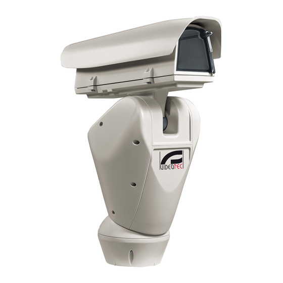
Pan & tilt devices have a label complying with CE markings. designation ULISSE RADICAL is the first Videotec ready to use network Full HD PTZ camera system that integrates exceptional factory-assembled combinations of camera and lens, Full HD 1080p, 60fps and 1/2" CMOS sensor, for day and night time broadcast quality video of extended outdoor areas. -
Page 11: Versions
24Vac. guarantee. The pan & tilt can be fitted with bracket for 2 VIDEOTEC LED illuminators for night surveillance The unit must not be dismantled or (illuminators not included). tampered with. The only exceptions... -
Page 12: Unpacking
6.2 Unpacking 6.2.1.2 Remove the protective packaging Open the housing and remove the protective When the product is delivered, make sure that the packaging. package is intact and that there are no signs that it has been dropped or scratched. If there are obvious signs of damage, contact the supplier immediately. -
Page 13: Safely Disposing Of Packaging Material
6.3 Contents 6.5 Preparatory work before installation Check the contents to make sure they correspond with the list of materials as below: 6.5.1 Attaching the bracket • Positioning unit Different types of supports are available (10 • Power supply base Accessories, page 31). -
Page 14: Installation
7 Installation 7.1 Connecting the cables to the base Never, under any circumstances, make any changes or connections that are not Insert the cables into the cable glands holding the shown in this handbook. Failure to follow base at about 20cm from the support. Tighten the the connection instructions that are given cable glands. -
Page 15: Fixing The Base To The Support
7.2 Fixing the base to the support 7.3 Connector board description CONNECTOR BOARD DESCRIPTION Use the screws and the washers supplied with the base. Connector/ Function Component Once you have positioned the gasket (01), fix the Board power supply base (02) onto the bracket (03) with screws (04), Signal cables serrated washers (05) and screw rings (06). -
Page 16: Connection Of The Power Supply Line
7.4 Connection of the power Earth cable should be about 10mm longer supply line than the other two, so that it will not be disconnected accidentally if pulled. Depending on the version, the device can be provided with different power supply voltages. The The power supply cable must be covered power supply voltage is indicated on the product by the silicone sheath (01) supplied. -
Page 17: 24Vac Power Line Connection
7.4.1 24Vac power line connection 7.4.2 120Vac and 230Vac power line connection Use a Class 2 listed UL tranformer, Cut the cables to the correct length and make the compliant with the Standards in force, only connections. Connect the power supply to the for products marked UL, powered at 24Vac. -
Page 18: Connection Of The Alarm Inputs, Of The Twilight Switch And Of The Relays
7.4.3 Connection of the alarm inputs, of Version with LED illuminators the twilight switch and of the relays CONNECTION OF THE ALARM INPUTS, OF THE TWILIGHT SWITCH AND OF THE RELAYS CAUTION! TNV-1 installation type. The AL1, AL2, AL3, Self-powered alarm inputs referred to the AGND installation is type TNV-1, do not connect it AL4 e AGND shared terminal... -
Page 19: Fixing The Upper Body
7.6 Fixing the upper body Fix the upper body (01) to the base (02) using the fixing screws (03) equipped with gaskets (04). Make sure the base seal is present and in good condition (05). Pay attention to the fixing. Tightening torque: 4Nm. -
Page 20: Led Illuminators Installation
(02). From Pan & Tilt, it is only possible to install VIDEOTEC illuminators. 7.7.1 Fitting the bracket Position the bracket (01) on the bottom of the housing as shown in figure. Install the screws and the washers (02) in the holes (03) and tighten them. -
Page 21: Connection Of The Led Illuminators
7.8 Connection of the LED 7.9 LED illuminator activation illuminators and adjustment instructions Insert the power supply cables through the cable Once the adjustment is done the illuminator on glands by at least 25 cm. Tighten the cable glands. the left (MASTER) synchronizes and controls the illuminator on the right (SLAVE). -
Page 22: Led Illuminator Switching On Threshold Adjustment
7.9.2 LED illuminator switching on 7.9.3 LED illuminator power adjustment threshold adjustment The illuminator on the right must always be set to minimum power. The illuminator on the right must always be set to maximum brightness. The illuminator is set in the factory to provide maximum power. -
Page 23: Switching On
8 Switching on Make sure that all parts are fastened down firmly and safely. Make sure that the unit and other components of the installation are closed The unit is switched on by connecting the power so that it is impossible to come into contact supply. -
Page 24: Configuration
9 Configuration 9.1.1 Home Page The product control interface is displayed if login is 9.1 Web interface successful. The unit is configured to obtain an IP address from a DHCP server. Browsers supported: Microsoft Internet Explorer, Google Chrome, Mozilla Firefox. The MAC Address is contained on the label that is on the CPU board. -
Page 25: User Controls Page
9.1.2 User Controls page • Iris close/Iris open/Auto iris To control the device through the browser, select the User Control entry. A new window will open with a virtual keyboard to enter commands. Fig. 39 • Wiper/Washer Fig. 40 • Day: Activate the camera's IR filter. If available, it turns off the LED illuminators. -
Page 26: Device Parameters Page
9.1.3 Device Parameters Page 9.1.5 Network Configuration page From menu entry Device Parameters it is possible to From menu entry Network it is possible to change set the name of the device and view other additional the setting of the Pan & Tilt network. It is possible information. -
Page 27: User Configuration Page
9.1.7 Movement Parameters page NTP Server: It is also possible to specify if the device needs to be synchronised with an external NTP From menu entry Movement Parameters it is possible (Network Time Protocol) server. to control, via web, all Pan & Tilt parameters. •... -
Page 28: Autopan Page
9.1.7.1 Autopan Page 9.1.8 Preset Parameters page From menu entry Autopan it is possible to specify the From menu entry Preset Parameters a number of preset autopan start and end. parameters relative to the presets can be configured: • Scan Speed: The speed, measured in degrees to the second, at which a preset is reached by explicit operator request. -
Page 29: Digital I/O Page
9.1.10 Digital I/O Page 9.1.11 Washer page From menu entry Digital I/O it is possible to configure From the Wash System menu, it is possible to the digital channels available in the device. What configure the device wash system functions. follows is a brief description of the configurable parameters for each digital input. -
Page 30: Camera Settings Page
9.1.12 Camera Settings page 9.1.13 Tools Page The parameters of the IP camera that were set at From menu entry Tools it is possible to re-set the first start up can be edited in the Camera Parameters predefined values for the entire configuration of section. -
Page 31: Factory Default
9.1.14 Factory Default In order to connect the web camera you must use the program VTTunnel, available in the Tools menu. If the password is no longer available, you When the program starts, a list of networked devices can also restore the factory settings by will be shown. -
Page 32: Accessories
10 Accessories 10.1.1 Washing system connection CAUTION! TNV-1 installation type. The For further details on configuration and installation is type TNV-1, do not connect it use, refer to the relative manual. to SELV circuits. 10.1 Washer CAUTION! In order to reduce the risk of fire, only use UL Listed or CSA certified cables The P&T can be equipped with an external pump that with sections greater than or equal to... -
Page 33: Wall Mount Bracket
10.2 Wall mount bracket 10.4 Power supply with illuminator control Wall bracket with internal cable channel. Weather-proof box with power supply and control of the illuminators. Fig. 61 Fig. 63 Version of the standard box. 10.3 Parapet bracket Parapet bracket with internal cable channel. Fig. -
Page 34: Maintenance
11 Maintenance 13 Disposal of waste materials Maintenance must be carried out by personnel trained to operate on electrical This symbol mark and recycle system circuits. are applied only to EU countries and not 11.1 Fuses replacement applied to the countries in the other area of the world. -
Page 35: Technical Data
15 Technical data 15.3 Electrical Supply voltage/Current consumption: 15.1 General • 230Vac, 0.4A, 50/60Hz Constructed from aluminium and tecnopolymer • 24Vac, 4A (8A with LED illuminators), 50/60Hz Epoxypolyester powder painting, RAL9002 colour • 120Vac, 0.8A, 50/60Hz Top mount (OTT) Power consumption: Transmission through toothed belt •... -
Page 36: Camera
15.5 Camera 15.6 Lenses Day/Night Full HD, 60fps, CMOS 1/1.9" sensor Zoom 18x, 8.6-154mm, F2.5 Effective Pixels: 2.38 Megapixel Zoom 33x, 15.2-500mm, F3.0 (Thermal compensation system and Visible Cut Filter) Minimum Illumination Zoom 18x, Colour (ICR-OFF): 15.7 Environment • 0.08lx, 50 IRE F2.5, 1/30s Minimum Illumination Zoom 18x, B/W (ICR-ON): Indoor/Outdoor •... -
Page 37: Technical Drawings
16 Technical drawings The dimensions of the drawings are in millimetres. Fig. 65 ULISSE RADICAL, Zoom 18x. MNVCUPKPLUS_1625_EN... - Page 38 Fig. 66 ULISSE RADICAL, Zoom 18x, version pre-arranged for the installation of two LED illuminators. MNVCUPKPLUS_1625_EN...
- Page 39 MNVCUPKPLUS_1625_EN...
- Page 40 Email: info@videotec.com Tel. +33 1 60491816 - Fax +33 1 69284736 Email: info.fr@videotec.com Asia Pacific Videotec (HK) Ltd Americas Videotec Security, Inc. Flat 8, 19/F. On Dak Industrial Building, No. 2-6 Wah Sing Street Gateway Industrial Park, 35 Gateway Drive, Suite 100 Kwai Chung, New Territories - Hong Kong Plattsburgh, NY 12901 - U.S.A.
- Page 41 ITALIANO ULISSE RADICAL Unità PTZ IP con telecamera ed ottica integrate Italiano - Manuale di istruzioni...
- Page 43 Sommario I T A L I A N O 1 Informazioni sul presente manuale ................6 1.1 Convenzioni tipografiche ............................. 6 2 Note sul copyright e informazioni sui marchi commerciali ........6 3 Norme di sicurezza ......................6 4 Identificazione ....................... 9 4.1 Descrizione e designazione del prodotto .......................
- Page 44 9.1 Interfaccia web ...............................23 9.1.1 Pagina Home ...................................23 9.1.2 Pagina Controlli Utente ...............................24 9.1.3 Pagina Parametri Dispositivo ............................25 9.1.4 Pagina Statistiche Dispositivo ............................25 9.1.5 Pagina Configurazione Rete ..............................25 9.1.6 Pagina Configurazione Utenti ............................26 9.1.7 Pagina Parametri Movimento ............................26 9.1.7.1 Pagina Autopan ......................................27 9.1.7.2 Pagina Patrol .........................................27 9.1.7.3 Pagina Richiamo Movimenti ...................................27 9.1.8 Pagina Parametri Preset ..............................27...
-
Page 45: Informazioni Sul Presente Manuale
1 Informazioni sul presente 3 Norme di sicurezza manuale ATTENZIONE! L’impianto elettrico al quale è collegata l’unità deve essere dotato di Prima di installare e utilizzare questa unità, leggere un interruttore di protezione bipolare attentamente tutta la documentazione fornita. Tenere automatico da 20A max. - Page 46 • Prima di eseguire qualsiasi operazione assicurarsi • Questo dispositivo è stato progettato per essere di togliere tensione al prodotto. fissato e collegato in maniera permanente su un edificio o su una struttura adeguata. Il • Non utilizzare cavi con segni di usura o dispositivo deve essere fissato e collegato in invecchiamento.
- Page 47 • Non permettere l’uso dell’apparecchio a bambini o • Adottare le dovute precauzioni per evitare di personale non autorizzato. danneggiare l’apparecchiatura con scariche elettrostatiche. • La manutenzione del dispositivo deve essere eseguita solo da personale qualificato. Durante le • L’unità è stata realizzata per essere collegata operazioni di manutenzione l'operatore è...
-
Page 48: Identificazione
CE. del prodotto ULISSE RADICAL è il primo sistema PTZ Full HD di rete Videotec pronto all'uso che integra eccezionali combinazioni di ottica e telecamera preconfigurate, Full HD 1080p, 60fps e sensori CMOS da 1/2", per video di qualità broadcast notte e giorno di estese aree esterne. -
Page 49: Versioni
24Vac. garanzia. Il brandeggio può essere dotato di un supporto per montaggio di 2 illuminatori a LED VIDEOTEC per la L'unità non deve essere smontata o visione notturna (illuminatori non inclusi). manomessa. Le uniche eccezioni sono... -
Page 50: Disimballaggio
6.2 Disimballaggio 6.2.1.2 Estrazione dell'imballo protettivo Dopo aver aperto la custodia, estrarre l'imballaggio Alla consegna del prodotto verificare che l'imballo protettivo. sia integro e non presenti segni evidenti di cadute o abrasioni. In caso di danni evidenti all'imballo contattare immediatamente il fornitore. In caso di restituzione del prodotto malfunzionante è... -
Page 51: Smaltimento In Sicurezza Dei Materiali Di Imballaggio
6.3 Contenuto 6.5 Lavoro preparatorio prima dell’installazione Controllare che il contenuto sia corrispondente alla lista del materiale sotto elencata: 6.5.1 Fissaggio del supporto • Unità di posizionamento Sono disponibili diversi tipi di supporto (10 • Base di alimentazione Accessori, pagina 31). Scegliere il supporto adeguato •... -
Page 52: Installazione
7 Installazione 7.1 Collegamento dei cavi alla base Non effettuare per nessun motivo alterazioni o collegamenti non previsti Introdurre i cavi all’interno dei pressacavi tenendo la in questo manuale. Il mancato rispetto base a circa 20cm dal supporto. Serrare i pressacavi. delle indicazioni fornite nel manuale in I pressacavi sono adatti per cavi con diametro merito ai collegamenti può... -
Page 53: Fissaggio Della Base Al Supporto
7.2 Fissaggio della base al 7.3 Descrizione della scheda supporto connettori DESCRIZIONE DELLA SCHEDA CONNETTORI Utilizzare le viti e le rondelle fornite con la base. Connettore/ Funzione Componente Dopo aver posizionato la guarnizione (01), fissare la Alimentazione della scheda base (02) sul supporto (03) utilizzando le viti (04), le Cavi di segnale rondelle dentellate (05) e gli anelli per vite (06). -
Page 54: Collegamento Della Linea Di Alimentazione
7.4 Collegamento della linea di Il cavo di terra deve essere più lungo degli alimentazione altri due di circa 10mm per prevenirne il distacco accidentale a causa dello A seconda della versione, al dispositivo possono stiramento. essere fornite diverse tensioni di alimentazione. Il valore di tensione di alimentazione è... -
Page 55: Collegamento Della Linea Di Alimentazione In 24Vac
7.4.1 Collegamento della linea di 7.4.2 Collegamento della linea di alimentazione in 24Vac alimentazione in 120Vac e 230Vac Tagliare a misura i cavi e realizzare i collegamenti. Per i prodotti marcati UL alimentati a 24Vac, Collegare la linea di alimentazione al seguente utilizzare un trasformatore UL listed Classe morsetto: CN1. -
Page 56: Collegamento Degli Ingressi Di Allarme, Dell'interruttore Crepuscolare E Dei Relè
7.4.3 Collegamento degli ingressi di Versione con illuminatori a LED allarme, dell'interruttore crepuscolare e COLLEGAMENTO DEGLI INGRESSI DI ALLARME, DELL'INTERRUTTORE CREPUSCOLARE E DEI RELÈ dei relè AL1, AL2, AL3, Ingressi di allarme auto-alimentati riferiti al ATTENZIONE! L'installazione è di tipo TNV-1. AL4 e AGND morsetto comune AGND Non collegare a circuiti SELV. -
Page 57: Fissaggio Del Corpo Superiore
7.6 Fissaggio del corpo superiore Fissare il corpo superiore (01) alla base (02) tramite le viti di fissaggio (03) dotate di guarnizioni (04). Controllare che sia presente e in buono stato la guarnizione della base (05). Prestare attenzione durante il fissaggio. Coppia di serraggio: 4Nm. -
Page 58: Montaggio Degli Illuminatori A Led
Per un corretto funzionamento si devono sempre installare entrambi gli illuminatori. Sul brandeggio è possibile installare esclusivamente illuminatori VIDEOTEC. 7.7.1 Montaggio della staffa Posizionare la staffa (01) sulla parte inferiore della custodia come illustrato in figura. Inserire le viti e le rondelle (02) nei fori (03) e serrarle. -
Page 59: Collegamento Degli Illuminatori A Led
7.8 Collegamento degli 7.9 Regolazione e modalità di illuminatori a LED attivazione degli illuminatori a Inserire i cavi di alimentazione per almeno 25cm attraverso i pressacavi. Serrare i pressacavi. Una volta effettuata la regolazione, l'illuminatore di sinistra (MASTER) sincronizza e controlla l'illuminatore di destra (SLAVE). -
Page 60: Regolazione Della Soglia Di Accensione Degli Illuminatori A Led
7.9.2 Regolazione della soglia di 7.9.3 Regolazione della potenza degli accensione degli illuminatori a LED illuminatori a LED L'illuminatore destro deve sempre essere L'illuminatore destro deve sempre essere impostato a luminosità massima. impostato a potenza minima. L'illuminatore è regolato in fabbrica per erogare la massima potenza. -
Page 61: Accensione
8 Accensione Accertarsi che tutte le parti siano fissate in maniera solida ed affidabile. Assicurarsi che l'unità e gli altri componenti dell’impianto siano chiusi in modo idoneo a Collegare l’alimentazione elettrica per accendere impedire il contatto con componenti sotto l'unità. tensione. -
Page 62: Configurazione
9 Configurazione 9.1.1 Pagina Home Se il login viene effettuato con successo, verrà 9.1 Interfaccia web mostrata l'interfaccia di gestione del prodotto. L'unità è configurata per ottenere l'indirizzo IP da un server DHCP. Browser supportati: Microsoft Internet Explorer, Google Chrome, Mozilla Firefox. Il MAC Address è... -
Page 63: Pagina Controlli Utente
9.1.2 Pagina Controlli Utente • Iris close/Iris open/Auto iris Per controllare il dispositivo via browser, selezionare la voce Controlli Utente. Si aprirà una nuova finestra con una tastiera virtuale per inviare i comandi. Fig. 39 • Wiper/Washer Fig. 40 • Day: Attiva il filtro IR della camera. Se presenti, spegne gli illuminatori a LED. -
Page 64: Pagina Parametri Dispositivo
9.1.3 Pagina Parametri Dispositivo 9.1.5 Pagina Configurazione Rete Alla voce del menu Parametri Dispositivo è possibile Alla voce del menu Rete è possibile cambiare impostare il nome del dispositivo e visualizzare altre l'impostazione di rete del brandeggio. È possibile informazioni aggiuntive. decidere se il dispositivo debba avere un indirizzo assegnato staticamente, dinamicamente con DHCP o autogenerato. -
Page 65: Pagina Configurazione Utenti
9.1.7 Pagina Parametri Movimento Server NTP: È possibile inoltre specificare se il dispositivo debba sincronizzarsi con un server NTP Alla voce del menu Parametri Movimento è possibile (Network Time Protocol) esterno. controllare via web tutti i parametri del brandeggio. • DISABILITATO: Selezionare questa opzione se non •... -
Page 66: Pagina Autopan
9.1.7.1 Pagina Autopan 9.1.8 Pagina Parametri Preset Alla voce del menu Autopan e possibile specificare il Alla voce del menu Parametri Preset sono preset di inizio e di fine dell'autopan. configurabili alcuni parametri relativi ai preset: • Velocità Scan: La velocità in gradi al secondo con cui viene raggiunto un preset su richiesta esplicita dell'operatore. -
Page 67: Pagina I/O Digitali
9.1.10 Pagina I/O Digitali 9.1.11 Pagina Washer Alla voce del menu I/O Digitali è possibile configurare Alla voce del menu Impianto di lavaggio è possibile i canali digitali presenti nel dispositivo. Segue una configurare le funzionalità del sistema di lavaggio del breve descrizione dei parametri configurabili per dispositivo. -
Page 68: Pagina Parametri Telecamera
9.1.12 Pagina Parametri Telecamera 9.1.13 Pagina Strumenti I parametri della camera IP che sono stato impostati Alla voce del menu Strumenti è possibile reimpostare al primo avvio sono modificabili alla voce del menu i valori predefiniti per tutta la configurazione del Parametri Camera. -
Page 69: Factory Default
9.1.14 Factory Default Per potersi connettere all'interfaccia web della telecamera è necessario utilizzare l'applicativo Se la password di accesso non è più VTTunnel, avviabile dalla voce di menu Strumenti. disponibile, è possibile ripristinare le All'avvio dell'applicativo verrà mostrato un elenco di impostazioni di fabbrica tramite un tasto di dispositivi collegati in rete. -
Page 70: Accessori
10 Accessori 10.1.1 Collegamento dell'impianto di lavaggio Per ulteriori dettagli sulla configurazione ATTENZIONE! L'installazione è di tipo TNV-1. e l’utilizzo fare riferimento al manuale del Non collegare a circuiti SELV. relativo accessorio. ATTENZIONE! Per ridurre il rischio di 10.1 Impianto di lavaggio incendio usare solamente cavi certificati UL Listed o CSA aventi sezioni maggiori o Il brandeggio può... -
Page 71: Supporto Da Parete
10.2 Supporto da parete 10.4 Alimentatore con controllo degli illuminatori Supporto per montaggio a parete con passaggio interno cavi. Scatola stagna con alimentatore e controllo degli illuminatori. Fig. 63 Versione della scatola standard. Fig. 61 10.3 Supporto da parapetto Supporto per montaggio a parapetto con passaggio interno cavi. -
Page 72: Manutenzione
11 Manutenzione 13 Smaltimento dei rifiuti La manutenzione deve essere eseguita solo Questo simbolo e il sistema di riciclaggio da personale qualificato ad intervenire su sono validi solo nei paesi dell'EU e non circuiti elettrici. trovano applicazione in altri paesi del mondo. -
Page 73: Dati Tecnici
15 Dati tecnici 15.3 Elettrico Tensione di alimentazione/Corrente assorbita: 15.1 Generale • 230Vac, 0.4A, 50/60Hz Costruzione in pressofusione di alluminio e • 24Vac, 4A (8A con illuminatori a LED), 50/60Hz tecnopolimero • 120Vac, 0.8A, 50/60Hz Verniciatura a polveri di epossipoliestere, colore Potenza assorbita: RAL9002 •... -
Page 74: Telecamere
15.5 Telecamere 15.6 Ottiche Day/Night Full HD, 60fps, sensore CMOS 1/1.9" Zoom 18x, 8.6-154mm, F2.5 Pixels Effettivi: 2.38 Megapixel Zoom 33x, 15.2-500mm, F3.0 (Sistema di compensazione termica e filtro anti riverbero -Visibile Illuminazione Minima zoom 18x, colore (ICR-OFF): Cut Filter) •... -
Page 75: Disegni Tecnici
16 Disegni tecnici Le dimensioni dei disegni sono espresse in millimetri. Fig. 65 ULISSE RADICAL, Zoom 18x. MNVCUPKPLUS_1625_IT... - Page 76 Fig. 66 ULISSE RADICAL, Zoom 18x, versione con predisposizione per il montaggio di due illuminatori a LED. MNVCUPKPLUS_1625_IT...
- Page 77 MNVCUPKPLUS_1625_IT...
- Page 78 Email: info@videotec.com Tel. +33 1 60491816 - Fax +33 1 69284736 Email: info.fr@videotec.com Asia Pacific Videotec (HK) Ltd Americas Videotec Security, Inc. Flat 8, 19/F. On Dak Industrial Building, No. 2-6 Wah Sing Street Gateway Industrial Park, 35 Gateway Drive, Suite 100 Kwai Chung, New Territories - Hong Kong Plattsburgh, NY 12901 - U.S.A.
- Page 79 FRANÇAIS ULISSE RADICAL Unité PTZ avec caméra et objectif intégrés Français - Manuel d’instructions...
- Page 81 Sommaire F R A N Ç A I S 1 À propos de ce mode d’emploi ..................5 1.1 Conventions typographiques ..........................5 2 Notes sur le copyright et informations sur les marques de commerce ..... 5 3 Normes de securité ......................5 4 Identification ........................
- Page 82 9.1 Interface web ................................22 9.1.1 Page Home ....................................22 9.1.2 Page Contrôles Utilisateur ..............................23 9.1.3 Page Paramètres Dispositif ..............................24 9.1.4 Page Statistiques Dispositif ..............................24 9.1.5 Page Configuration Réseau ..............................24 9.1.6 Page Configuration Utilisateurs ............................25 9.1.7 Page Paramètres Mouvement ............................25 9.1.7.1 Page Autopan.......................................26 9.1.7.2 Page Patrol ........................................26 9.1.7.3 Page Rappel Mouvements ..................................26 9.1.8 Page Paramètres Preset ...............................26...
-
Page 83: À Propos De Ce Mode D'emploi
1 À propos de ce mode 3 Normes de securité d’emploi ATTENTION! Le circuit électrique auquel l'unité est reliée doit être équipé d'un Avant d'installer et d'utiliser cette unité, lire interrupteur de protection bipolaire attentivement toute la documentation fournie. automatique de 20A max. Cet interrupteur Garder le manuel à... - Page 84 • Sectionner l'alimentation avant de procéder à • Cet appareil est conçu pour être fixé et relié de toute opération. manière permanente sur un bâtiment ou une structure adéquate. L'appareil doit être fixé et relié • Ne pas utiliser de câbles usés ou endommagés. de manière permanente avant d'effectuer toute •...
- Page 85 • Ne pas laisser l'appareil à portée des enfants ou de • Adopter les précautions utiles pour éviter personnes non autorisées. d'endommager l'appareil à la suite de décharges électrostatiques. • L'entretien du dispositif doit uniquement être effectué par un personnel qualifié. Durant les •...
-
Page 86: Identification
CE. produit ULISSE RADICAL est le premier système PTZ Full HD réseau de Videotec prêt à l'emploi qui intègre des combinaisons exceptionnelles de caméra et objectif préconfigurés, Full HD, 1080p, 60fps et capteur de 1/2" pour vidéos de qualité broadcast nuit et jour de vastes zones externes. -
Page 87: Versions
24Vac. l’annulation de la garantie. La tourelle peut être munie d’un support pour l’utilisation de 2 projecteurs à LED VIDEOTEC pour L'unité ne doit être ni démontée ni altérée. vision nocturne (projecteurs à prévoir en plus). Les seules exceptions concernent les opérations de montage et d'entretien... -
Page 88: Déballage
6.2 Déballage 6.2.1.2 Extraction de l'emballage de protection Lors de la livraison du produit, vérifier que Après avoir ouvert le caisson, extraire l'emballage de l’emballage est en bon état et l’absence de tout signe protection. évident de chute ou d’abrasion. En cas de dommages évidents, contacter immédiatement le fournisseur. -
Page 89: Opérations À Effectuer Avant L'installation
6.3 Contenu 6.5 Opérations à effectuer avant l’installation Contrôler que le contenu correspond à la liste matériel indiquée ci-dessous: 6.5.1 Fixation du support • Unité de positionnement Plusieurs types de supports sont disponibles (10 • Base d'alimentation Accessoires, page 31). Choisir le support convenable •... -
Page 90: Installation
7 Installation 7.1 Connexion des câbles à la base Ne procéder sous aucun prétexte à des modifications ou des connexions non Passer les câbles dans les presse-câbles en prévues dans ce manuel. L’utilisation maintenant la base à environ 20cm du support. Serrer d’appareils inadéquats peut comporter les presse-étoupes. -
Page 91: Fixage De La Base Au Support
7.2 Fixage de la base au support 7.3 Description de la carte de connexion Utiliser les vis et les rondelles fournies avec la base. DESCRIPTION DE LA CARTE DE CONNEXION Connecteur/ Fonction Après avoir positionné le joint (01), fixer la base (02) Composant au support (03) en utilisant les vis (04), les rondelles à... -
Page 92: Connexion De La Ligne D'alimentation
7.4 Connexion de la ligne Le câble de terre doit être plus long des d'alimentation deux autres d'environ 10mm pour éviter tout détachement accidentel. Selon la version, différentes tensions d'alimentation peuvent être fournies au dispositif. La valeur de Le câble d'alimentation doit en outre être tension d'alimentation est reportée sur l'étiquette couvert de la gaine en silicone (01) fournie. -
Page 93: Connexion De La Ligne D'alimentation En 24Vac
7.4.1 Connexion de la ligne 7.4.2 Raccordement de la ligne d'alimentation en 24Vac d'alimentation en 120Vac et 230Vac Couper les câbles à la longueur nécessaire et Il faut, uniquement pour les produits procéder aux connexions. Connecter la ligne marqués UL alimentés à 24Vac, utiliser un d'alimentation avec la borne: CN1. -
Page 94: Branchement Des Entrées D'alarme, De L'interrupteur Crépusculaire Et Des Relais
7.4.3 Branchement des entrées Version avec projecteurs à LED d'alarme, de l'interrupteur crépusculaire BRANCHEMENT DES ENTRÉES D'ALARME, DE L'INTERRUPTEUR CRÉPUSCULAIRE ET DES RELAIS et des relais AL1, AL2, AL3, Entrées d'alarme auto-alimentées relatives à la ATTENTION! L'installation est du type TNV- AL4 e AGND borne commune AGND. -
Page 95: Fixation Du Corps Supérieur
7.6 Fixation du corps supérieur Fixer le corps supérieur (01) à la base (02) au moyen des vis de fixation (03) pourvues de joints (04). Contrôler que le joint de la base est en place et en bon état (05). Faire attention pendant la fixation. -
Page 96: Montage Des Projecteurs À Led
(02). Pour en correct fonctionnement les deux projecteurs doivent toujours être montés ensemble. Seuls des projecteurs VIDEOTEC peuvent être installés sur la tourelle. 7.7.1 Montage de l’étrier Positionner l’étrier (01) sur la partie inférieure du caisson comme illustré en figure. Introduire les vis et les rondelles (02) dans les trous (03) et les serrer. -
Page 97: Branchement Des Projecteur À Led
7.8 Branchement des projecteur 7.9 Réglage et modalité à LED d'activation des projecteurs à Introduire les câbles d'alimentation de 25 cm au moins à travers les presse-étoupes. Serrer les presse- Une fois effectué le réglage, le projecteur de gauche étoupes. (MASTER) synchronise et contrôle le projecteur de droite (SLAVE). -
Page 98: Réglage Du Seuil D'allumage Des Projecteurs À Led
7.9.2 Réglage du seuil d'allumage des 7.9.3 Réglage de la puissance des projecteurs à LED projecteurs à LED Le projecteur de droite doit toujours être Le projecteur de droite doit toujours être configuré à la luminosité maximum. configuré à la puissance minimum. Le projecteur est réglé... -
Page 99: Allumage
8 Allumage Ne pas stationner à proximité du dispositif sous tension. N'intervenir sur le dispositif S'assurer que l'unité et les autres qu'avec l'alimentation coupée. composants de l'installation soient fermés de façon à empêcher le contact avec les Il suffit de brancher l'alimentation électrique pour composants sous tension. -
Page 100: Configuration
9 Configuration 9.1.1 Page Home Si le login est effectué avec succès, on pourra voir 9.1 Interface web l'interface de gestion de le produit. L’appareil est configuré pour obtenir l’adresse IP depuis un serveur DHCP. Logiciels de navigation supportés: Microsoft Internet Explorer, Google Chrome, Mozilla Firefox. -
Page 101: Page Contrôles Utilisateur
9.1.2 Page Contrôles Utilisateur • Iris close/Iris open/Auto iris Pour contrôler la dispositif par browser, sélectionner la mention Contrôle Utilisateur. Une nouvelle fenêtre s'ouvrira, avec un clavier virtuel pour sélectionner les commandes. Fig. 39 • Wiper/Washer Fig. 40 • Day: Activer le filtre IR de la chambre. Si présents, éteint les projecteurs à... -
Page 102: Page Paramètres Dispositif
9.1.3 Page Paramètres Dispositif 9.1.5 Page Configuration Réseau A la mention du menu Paramètres Dispositif il est A la mention du menu Réseau il est possible de possible de configurer le nom de le dispositif et changer la configuration de réseau de la tourelle. Il d'afficher d'autres informations supplementaire. -
Page 103: Page Configuration Utilisateurs
9.1.7 Page Paramètres Mouvement Serveur NTP: Il est également possible de mentionner si le dispositif doit se synchroniser avec A la mention du menu Paramètres Mouvement il est un serveur NTP (Network Time Protocol) externe. possible de contrôler par web tous les paramètres de •... -
Page 104: Page Autopan
9.1.7.1 Page Autopan 9.1.8 Page Paramètres Preset A la mention du menu Autopan il est possible A la mention du menu Paramètres Preset on peut d'indiquer le preset de début et de fin de l'autopan. configurer certains paramètres concernant les preset: •... -
Page 105: Page I/O Digitaux
9.1.10 Page I/O Digitaux 9.1.11 Page Washer Dans la carte I/O Digitaux il est possible de configurer Dans le menu Installation de Lavage, on peut les canaux digitaux présents dans le dispositif. Il y a configurer les fonctionnalités du système de lavage ci-dessous une courte description des paramètres du dispositif. -
Page 106: Page Paramètres Caméra
9.1.12 Page Paramètres Caméra 9.1.13 Page Instruments Les paramètres de la caméra IP qui ont été configurés A la mention du menu Instruments il est possible à la première mise en marche sont modifiables de reconfigurer les valeurs prédéfinies pour toute dans la section Paramètres Caméra. -
Page 107: Factory Default
9.1.14 Factory Default Afin de connecter la caméra IP, vous devez utiliser le programme de VTTunnel, démarrable du menu Si le mot de passe ne est plus disponible, Instruments. il est possible de rétablir les paramétrages Au lancement du programme, sera montrée une d’usine à... -
Page 108: Accessoires
10 Accessoires 10.1.1 Branchement du système de lavage Pour de plus amples informations sur la ATTENTION! L'installation est du type TNV- configuration et l'utilisation, consulter le 1. Ne pas la connecter à des circuits SELV. manuel de l'accessoire correspondant. ATTENTION! Pour réduire les risques 10.1 Système de lavage d’incendie, utiliser uniquement des câbles certifiés UL Listed ou CSA de sections égales... -
Page 109: Support Fixation Murale
10.2 Support fixation murale 10.4 Alimentateur avec contrôle des projecteurs. Support mural avec passage interne des câbles. Boîte étanche avec alimentateur et contrôle des projecteurs. Fig. 61 Fig. 63 Version du boîtier standard. 10.3 Support fixation sol Support de fixation au sol avec passage interne des câbles. -
Page 110: Entretien
11 Entretien 13 Élimination des déchets L’entretien doit être uniquement effectué Ce symbole et le système de recyclage ne par un personnel qualifié en matière de sont appliqués que dans les pays UE et non circuits électriques. dans les autres pays du monde. Votre produit est conçu et fabriqué... -
Page 111: Données Techniques
15 Données techniques 15.3 Électrique Tension d’alimentation/Courant absorbé: 15.1 Généralités • 230Vac, 0.4A, 50/60Hz Fabriqué en fonte d’aluminium et en technopolymère • 24Vac, 4A (8A avec projecteurs à LED), 50/60Hz Vernissage avec poudres époxypolyester, couleur • 120Vac, 0.8A, 50/60Hz RAL9002 Puissance absorbée: Caisson positionné... -
Page 112: Caméra
15.5 Caméra 15.6 Optiques Day/Night Full HD, 60fps, CMOS 1/1.9" capteur Zoom 18x, 8.6-154mm, F2.5 Pixels effectifs: 2.38 Megapixel Zoom 33x, 15.2-500mm, F3.0 (Système de compensation thermique et filtre anti-éblouissement Éclairage minimum Zoom 18x, Couleur (ICR-OFF): - Visible Cut Filter) •... -
Page 113: Dessins Techniques
16 Dessins techniques Les dimensions des dessins sont exprimées en millimètres. Fig. 65 ULISSE RADICAL, Zoom 18x. MNVCUPKPLUS_1625_FR... - Page 114 Fig. 66 ULISSE RADICAL, Zoom 18x, version avec prédisposition pour le montage des deux projecteurs à LED. MNVCUPKPLUS_1625_FR...
- Page 115 MNVCUPKPLUS_1625_FR...
- Page 116 Email: info@videotec.com Tel. +33 1 60491816 - Fax +33 1 69284736 Email: info.fr@videotec.com Asia Pacific Videotec (HK) Ltd Americas Videotec Security, Inc. Flat 8, 19/F. On Dak Industrial Building, No. 2-6 Wah Sing Street Gateway Industrial Park, 35 Gateway Drive, Suite 100 Kwai Chung, New Territories - Hong Kong Plattsburgh, NY 12901 - U.S.A.
- Page 117 DEUTSCH ULISSE RADICAL PTZ Einheit mit integrierten Kamera und Optik Deutsch - Bedienungsanleitung...
- Page 119 Inhaltsverzeichnis D E U T S C H 1 Allgemeines ........................5 1.1 Schreibweisen ................................5 2 Anmerkungen zum Copyright und Informationen zu den Handelsmarken ..... 5 3 Sicherheitsnormen ......................5 4 Identifizierung ....................... 8 4.1 Beschreibung und Bezeichnung des Produktes ................... 8 4.2 Kennzeichnung des Produkts..........................
- Page 120 9.1 Web-Schnittstelle ..............................22 9.1.1 Home Seite ....................................22 9.1.2 Benutzersteuerung Seite ..............................23 9.1.3 Geräteparameter Seite ................................24 9.1.4 Gerätestatistiken Seite .................................24 9.1.5 Netzwerk-Konfiguration Seite ............................24 9.1.6 Benutzer-Konfiguration Seite ............................25 9.1.7 Bewegungsparameter Seite ..............................25 9.1.7.1 Autopan Seite.......................................26 9.1.7.2 Patrol Seite ........................................26 9.1.7.3 Bewegungsanforderung Seite ................................26 9.1.8 Preset-Parameter Seite ................................26 9.1.9 Preset-Parameter Seite (Fortgeschritten) ........................26 9.1.10 Digitale I/O Seite ..................................27...
-
Page 121: Allgemeines
1 Allgemeines 3 Sicherheitsnormen Vor Installation und Anwendung der Einheit ist die ACHTUNG! Die elektrische Anlage, an gesamte gelieferte Dokumentation aufmerksam zu der die Einheit angeschlossen ist, muss lesen. Zum späteren Nachschlagen das Handbuch in mit einem automatischen zweipoligen Reichweite aufbewahren. Schutzschalter 20A max ausgestattet sein. - Page 122 • Unterbrechen Sie die Stromversorgung, bevor die • Die Einrichtung ist für die dauerhafte Befestigung beschriebenen Arbeiten durchgeführt werden. und Verbindung in ein Gebäude oder eine andere geeignete Struktur konzipiert. Vor jeder Operation • Es dürfen keine Kabel mit Verschleiß- oder muss die Einrichtung dauerhaft befestigt und Alterungsspuren verwendet werden.
- Page 123 • Kindern oder unbefugten Personen ist der • Vermeiden Sie durch gebotene Vorkehrungen, Gebrauch des Gerätes zu untersagen. dass das Gerät durch elektrostatische Entladungen beschädigt wird. • Die Wartung der Einrichtung ist Fachleuten vorbehalten. Während der Wartungsarbeiten ist die • Die Einheit ist dafür ausgelegt, über ein dreipoliges tätige Person der Gefahr von Stromschlägen und Kabel angeschlossen zu werden.
-
Page 124: Identifizierung
Bezeichnung des Produktes Kennzeichnung entspricht. ULISSE RADICAL ist das erste einsatzbereite Netzwerk- Full-HD- PTZ- Kamerasystem von Videotec, dass außergewöhnliche Kombinationen von vorkonfigurierten Objektiv und Kamera, Full HD 1080p, 60fps und 1/2" CMOS Sensor, für Tages- und Nachtzeit Broadcast-Qualität Video von weiten Außenbereichen integriert. -
Page 125: Versionen
Spannung von 24Vac der Gewährleistungsrechte. betrieben werden. Der S-N-Kopf kann mit einer Halterung Die Einheit darf nicht auseinandergebaut für 2 VIDEOTEC LED- Scheinwerfer für die werden, und es dürfen keine Nachtüberwachung (Scheinwerfer nicht Veränderungen daran vorgenommen eingeschlossen). -
Page 126: Entfernen Der Verpackung
6.2 Entfernen der Verpackung 6.2.1.2 Herausziehen der Schutzverpackung Nach Öffnen des Gehäuse, die Schutzverpackung Bei der Lieferung des Produktes ist zu prüfen, ob die herausziehen. Verpackung intakt ist oder offensichtliche Anzeichen von Stürzen oder Abrieb aufweist. Bei offensichtlichen Schadensspuren an der Verpackung muss umgehend der Lieferant verständigt werden. -
Page 127: Auf Die Installation Vorbereitende Tätigkeiten
6.3 Inhalt 6.5 Auf die Installation vorbereitende Tätigkeiten Prüfen Sie, ob der Inhalt mit der nachstehenden Materialliste übereinstimmt: 6.5.1 Befestigung der Halterung • Positionierungseinheit Verschiedene Halterungen sind (10 Zubehör, Seite • Basis für Netzstromversorgung 31). Das geeignetste für die Installation auswählen •... -
Page 128: Installation
7 Installation 7.1 Anschließen der Kabel an die Basis Unter keinen Umständen dürfen Veränderungen oder Anschlüsse Die Kabel in den Kabelschellen einführen, während vorgenommen werden, die in diesem die Basis etwa 20cm von der Halterung entfernt Handbuch nicht genannt sind. Die gehalten wird. -
Page 129: Befestigung Der Basis An Der Halterung
7.2 Befestigung der Basis an der 7.3 Beschreibung der Karte Halterung Anschlüsse BESCHREIBUNG DER KARTE ANSCHLÜSSE Verwenden Sie die mit der Basis gelieferten Schrauben und Unterlegscheiben. Verbinder/ Funktion Komponente Nach der Positionierung der Dichtung (01), die Basis Platinenversorgung (02) mit den Schrauben (04), den Zahnscheiben (05) Signalkabel und den Ringen für Schrauben (06) an der Halterung Ethernet... -
Page 130: Anschluss Der Stromversorgung
7.4 Anschluss der Das Erdungskabel muss um etwa 10mm Stromversorgung länger sein, als die anderen beiden Kabel, um das ungewollte Lösen durch Ziehen des Je nach Version kann die Vorrichtung mit Kabels zu verhindern. unterschiedlichen Versorgungsspannungen geliefert werden. Der Wert der Versorgungsspannung ist Ferner muss das Versorgungskabel von auf dem Kenndatenschildchen des Produktes einer Silikonummantelung (01) überzogen... -
Page 131: Anschluss Der Stromversorgunglinie 24Vac
7.4.1 Anschluss der 7.4.2 Anschluss der Versorgungsleitung Stromversorgunglinie 24Vac in 120Vac und 230Vac Die Kabel zuschneiden und die unten beschriebenen Lediglich für die Produkte mit UL - Anschlüsse vornehmen. Die Versorgungsleitung am Markierung mit 24Vac - Versorgung ein Klemmen anschließen: CN1. UL - Speisetransformator der Klasse 2 verwenden, welches den geltenden Richtlinien entspricht. -
Page 132: Anschluss Der Alarmeingänge, Der Dämmerungsschalter Und Der Relais
7.4.3 Anschluss der Alarmeingänge, der Version mit LED- Scheinwerfern Dämmerungsschalter und der Relais ANSCHLUSS DER ALARMEINGÄNGE, DER DÄMMERUNGSSCHALTER UND DER RELAIS ACHTUNG! Die Anlage gehört zum Typ TNV- AL1, AL2, AL3, Sich selbstversorgende Alarmeingänge, bezogen 1. Nicht an Kreisläufe SELV anschließen. AL4 e AGND auf gemeinsame Klemme AGND. -
Page 133: Befestigung Des Oberen Körpers
7.6 Befestigung des oberen Körpers Den oberen Körper (01) mit den Spannschrauben (03) und Dichtungen (04) an der Basis (02) befestigen. Prüfen Sie, ob die Dichtung (05) der Basis vorhanden und in einwandfreiem Zustand ist. Abb. 21 Auf die Befestigung achten. Anzugsdrehmoment: 4Nm. -
Page 134: Montage Der Scheinwerfer Mit Led
Bügels (02) anbringen. Aus funktionstechnischen Gründen müssen stets beide Scheinwerfer zusammen montiert werden. Am Schwenk-Neige-Kopf dürfen nur Scheinwerfer von VIDEOTEC installiert werden. 7.7.1 Bügelmontage Den Bügel (01) im unteren Teil des Gehäuses positionieren, wie in der Abbildung gezeigt. Die Schrauben und die Unterlegescheiben (02) in die Bohrungen (03) einfügen und festziehen. -
Page 135: Anschluss Der Led-Scheinwerfer
7.8 Anschluss der LED- 7.9 Einstellung und Scheinwerfer Aktivierungsarten der LED- Scheinwerfer Die Versorgungskabel um mindestens 25 cm durch die Kabelschellen stecken. Die Nach der Regelung synchronisiert und steuert Kabelverschraubungen festziehen. der linke Scheinwerfer (MASTER ) den rechten Scheinwerfer (SLAVE). Der Dämmerungsschalter ermittelt das Licht in der 25cm 25cm... -
Page 136: Einstellung Der Einschaltschwelle Der Led-Scheinwerfer
7.9.2 Einstellung der Einschaltschwelle 7.9.3 Einstellung der Leistung der LED- der LED-Scheinwerfer. Scheinwerfer. Der rechte Scheinwerfer muss immer auf Der rechte Scheinwerfer muss immer auf die maximale Helligkeit eingestellt sein. die minimale Leistung eingestellt sein. Der Scheinwerfer wird im Werk zur Erbringung maximaler Leistung eingestellt. -
Page 137: Einschaltung
8 Einschaltung Vergewissern Sie sich, dass alle Teile fest und zuverlässig befestigt sind. Sicherstellen, das die Einheit und die anderen Bauteile der Anlage korrekt Für das Einschalten der Einheit die elektrische geschlossen sind, um den Kontakt mit Versorgung anzulegen. unter Spannung stehenden Bauteilen zu Die elektrische Versorgung abtrennen, um die Einheit verhindern. -
Page 138: Konfiguration
9 Konfiguration 9.1.1 Home Seite Wenn der Login erfolgreich abgeschlossen wurde, 9.1 Web-Schnittstelle wird die Steuer-Schnittstelle des Produktes angezeigt. Die Einheit ist konfiguriert, um eine IP-Adresse von einem DHCP-Server zu erhalten. Unterstützte Browser: Microsoft Internet Explorer, Google Chrome, Mozilla Firefox. Die MAC Address wird auf dem Etikett an der CPU-Karte angegeben. -
Page 139: Benutzersteuerung Seite
9.1.2 Benutzersteuerung Seite • Iris close/Iris open/Auto iris Um die Einrichtung via Browser zu steuern, wählen Sie den Eintrag Benutzersteuerung. Es öffnet sich ein neues Fenster mit einer virtuellen Tastatur zum Absenden von Befehlen. Abb. 39 • Wiper/Washer Abb. 40 •... -
Page 140: Geräteparameter Seite
9.1.3 Geräteparameter Seite 9.1.5 Netzwerk-Konfiguration Seite Im Menü-Eintrag Geräteparameter können der Im Menü-Eintrag Netzwerk kann die Netzwerk- Name der Einrichtung eingestellt und andere Einstellung des Schwenk-Neige-Kopfes geändert Zusatzinformationen angezeigt werden. werden. Es kann eingestellt werden, ob das Gerät eine statisch oder dynamisch mit DHCP zugewiesene oder eine selbstgenerierte Adresse haben muss. -
Page 141: Benutzer-Konfiguration Seite
9.1.7 Bewegungsparameter Seite NTP-Server: Außerdem kann angegeben werden, ob das Gerät sich mit einem externen NTP (Network Im Menü-Eintrag Bewegungsparameter können via Time Protocol) Server synchronisieren muss. Internet alle Parameter des Schwenk-Neige-Kopfes • DEAKTIVIERT: Stellen Sie diese Option ein, wenn kontrolliert werden. -
Page 142: Autopan Seite
9.1.7.1 Autopan Seite 9.1.8 Preset-Parameter Seite Im Menü-Eintrag Autopan können die Presets für Im Menü-Eintrag Preset-Parameter sind einige Beginn und Ende des Autopan angegeben werden. Parameter der Presets konfigurierbar: • Scan Geschwindigkeit: Geschwindigkeit in Grad pro Sekunde, mit der ein Preset auf ausdrückliche Aufforderung des Bedieners erreicht wird. -
Page 143: Digitale I/O Seite
9.1.10 Digitale I/O Seite 9.1.11 Washer Seite Im Menü-Eintrag Digitale I/O können die digitalen Im Menü-Eintrag Scheibenwaschanlage kann der Kanäle der Einrichtung konfiguriert werden. Es Betrieb der Waschanlage konfiguriert werden. folgt eine kurze Beschreibung der konfigurierbaren Parameter für jeden Digitaleingang. •... -
Page 144: Kamera-Parameter Seite
9.1.12 Kamera-Parameter Seite 9.1.13 Werkzeuge Seite Die Parameter der IP-Kamera, die beim ersten Start Im Menü-Eintrag Werkzeuge können die eingestellt wurden, können im Abschnitt Kamera- gesamte Konfiguration der Einrichtung oder nur Parameter geändert werden. Im Abschnitt Kamera- bestimmte Abschnitte auf die vordefinierten Werte Parameter können außerdem der Zoomfaktor und zurückgesetzt werden. -
Page 145: Factory Default
9.1.14 Factory Default Um die IP-Kamera anzuschließen, müssen Sie das VTTunnel- Programm verwenden, aus dem Menü Falls das Kennwort nicht mehr verfügbar Werkzeuge bootfähig. ist, können mit einer Resettaste, die sich in Beim Start des Programmes,wird eine Liste von der Basis befindet, die Werkseinstellungen vernetzten Geräten angezeigt. -
Page 146: Zubehör
10 Zubehör 10.1.1 Anschluss der Waschanlage. ACHTUNG! Die Anlage gehört zum Typ TNV- Für weitere Details zur Konfiguration und 1. Nicht an Kreisläufe SELV anschließen. zum Gebrauch beachten Sie bitte das Handbuch des entsprechenden Geräts. ACHTUNG! Zur Senkung der Brandgefahr dürfen nur UL Listed oder CSA zertifizierte 10.1 Waschanlage Kabel benutzt werden, die mindestens... -
Page 147: Wandhalterung
10.2 Wandhalterung 10.4 Netzteil mit Steuerung der Scheinwerfer Wandhalterung mit interner Kabelführung. Dichtes Gehäuse mit Netzteil und Kontrolle der Scheinwerfer. Abb. 61 Abb. 63 Standardversion des Gehäuses. 10.3 Halterung für Brüstungsmontage Brüstunghalterung mit interner Kabelführung. Abb. 64 UL-zertifizierte Version des Gehäuses. Für weitere Infos bitte entsprechendes Kapitel beachten (7.4.3 Anschluss der Alarmeingänge, der Dämmerungsschalter... -
Page 148: Wartung
11 Wartung 13 Müllentsorgungsstellen Die Wartung darf nur von Fachleuten Dieses Symbol und das entsprechende vorgenommen werden, die befähigt sind, Recycling-System gelten nur für EULänder an elektrischen Schaltkreisen tätig zu und finden in den anderen Ländern der werden. Welt keine Anwendung. Ihr Produkt wurde entworfen und hergestellt 11.1 Wechsel der Sicherungen aus qualitativ hochwertigen Materialien und... -
Page 149: Technische Daten
15 Technische Daten 15.3 Elektrik Versorgungsspannung/Stromaufnahme: 15.1 Allgemeines • 230Vac, 0.4A, 50/60Hz Konstruktion aus Aluminiumdruckguss und • 24Vac, 4A (8A mit LED Scheinwerfern), 50/60Hz Technopolymer • 120Vac, 0.8A, 50/60Hz Pulverlackierung mit Epoxydpolyester, Farbe RAL9002 Leistungsaufnahme: Top mount (OTT) • 100W Zahnriemenantrieb •... -
Page 150: Kamera
15.5 Kamera 15.6 Optiken Day/Night Full HD, 60fps, CMOS 1/1.9" Sensor Zoom 18x, 8.6-154mm, F2.5 Effektive Pixel: 2.38 Megapixel Zoom 33x, 15.2-500mm, F3.0 (System für thermischem Ausgleich und Visible Cut Filter) Mindestbeleuchtung Zoom 18x, Farbe (ICR-OFF): 15.7 Umgebung • 0.08lx, 50 IRE F2.5, 1/30s Mindestbeleuchtung Zoom 18x, B/W (ICR-ON): Innen/Außen •... -
Page 151: Technische Zeichnungen
16 Technische Zeichnungen Die Abmessungen der Zeichnungen sind in Millimeter angegeben. Abb. 65 ULISSE RADICAL, Zoom 18x. MNVCUPKPLUS_1625_DE... - Page 152 Abb. 66 ULISSE RADICAL, Zoom 18x, Version mit Vorrüstung für zwei LED-Scheinwerfer. MNVCUPKPLUS_1625_DE...
- Page 153 MNVCUPKPLUS_1625_DE...
- Page 154 Email: info@videotec.com Tel. +33 1 60491816 - Fax +33 1 69284736 Email: info.fr@videotec.com Asia Pacific Videotec (HK) Ltd Americas Videotec Security, Inc. Flat 8, 19/F. On Dak Industrial Building, No. 2-6 Wah Sing Street Gateway Industrial Park, 35 Gateway Drive, Suite 100 Kwai Chung, New Territories - Hong Kong Plattsburgh, NY 12901 - U.S.A.
- Page 155 РУССКИЙ ULISSE RADICAL Устройство PTZ IP с встроенной телекамерой и оптикой Русский - Руководство по эксплуатации...
- Page 157 Содержание Р У С С К И Й 1 О настоящем руководстве ..................6 1.1 Типографские условные обозначения ......................6 2 Примечания в отношении авторского права и информация о торговых марках ..........................6 3 Правила техники безопасности ................6 4 Обозначение ......................... 9 4.1 Описание...
- Page 158 9 Конфигурация ......................23 9.1 Веб-интерфейс ..............................23 9.1.1 Главная страница (Home Page) ............................23 9.1.2 Страница пользовательских элементов управления ..................24 9.1.3 Страница параметров устройства (Device Parameters Page) ................25 9.1.4 Страница статистики устройства ..........................25 9.1.5 Страница конфигурации сети ............................25 9.1.6 Страница пользовательских настроек ........................26 9.1.7 Страница...
-
Page 159: О Настоящем Руководстве
1 О настоящем 3 Правила техники руководстве безопасности Перед установкой и использованием этого ПРЕДУПРЕЖДЕНИЕ! Система оборудования внимательно прочтите всю электропитания, к которой подключается устройство, должна предоставленную документацию. Всегда держите иметь автоматический двухполюсный руководство под рукой, чтобы им можно было выключатель цепи макс. 20 A. воспользоваться... - Page 160 • Перед выполнением любой операции • Это устройство должно быть подключено и проверьте, отключен ли источник питания. надежно закреплено на здании или подходящей конструкции. Устройство следует надежно • Не используйте кабели, которые кажутся закрепить и подключить перед выполнением изношенными или старыми. каких-либо...
- Page 161 • Не разрешайте детям или неуполномоченным • Предпринимайте все необходимые меры лицам использовать оборудование. предосторожности, чтобы предотвратить повреждение оборудования вследствие • Только опытные сотрудники должны проводить электрического разряда. техническое обслуживание устройства. При проведении технического обслуживания • Устройство предназначено для подключения оператор...
-
Page 162: Обозначение
этикетка, соответствующая маркировке типа устройства ULISSE RADICAL - это первая готовая к использованию сетевая PTZ-система компании Videotec с разрешением Full HD, которая объединяет в себе особую установленную на заводе-изготовителе систему камеры и объектива, Full HD 1080 пикселей, 60 кадров/с и КМОП- датчик... -
Page 163: Модели
в 24Vac. аннулирует гарантию. Поворотное устройство может быть оснащено кронштейном для 2 светодиодных осветителей Не следует демонтировать устройство VIDEOTEC для ночного наблюдения (осветители не или нарушать его целостность. входят в комплект оборудования). Единственным исключением являются операции по монтажу и техническому... -
Page 164: Распаковка
6.2 Распаковка 6.2.1.2 Снимите защитную упаковку. Откройте кожух и снимите защитную упаковку. При доставке устройства убедитесь, что упаковка не повреждена и не имеет явных признаков падения или царапин. В случае наличия видимых повреждений незамедлительно свяжитесь с поставщиком. В случае возврата неисправного устройства мы... -
Page 165: Комплект Оборудования
6.3 Комплект оборудования 6.5 Подготовительные работы перед установкой Проверьте комплект оборудования на соответствие представленному ниже списку 6.5.1 Установка кронштейна материалов: Доступны различные виды опорных конструкций • Устройство позиционирования (10 Комплектующие, страница 31). Выберите • Основание с подачей питания подходящий кронштейн для установки и •... -
Page 166: Монтаж
7 Монтаж 7.1 Подключение кабелей к основанию Никогда и ни при каких обстоятельствах не выполняйте изменений или Вставьте кабели в кабельные сальники, удерживая подключений, не описанных в основание на расстоянии около 20 см от опорной настоящем руководстве. Несоблюдение конструкции. Затяните кабельные сальники. изложенных... -
Page 167: Крепление Основания К Опорной Конструкции
7.2 Крепление основания к 7.3 Описание платы опорной конструкции подключения ОПИСАНИЕ ПЛАТЫ ПОДКЛЮЧЕНИЯ Используйте винты и шайбы, поставляемые вместе с основанием. Разъем/ Функция Элемент Установите уплотнительное кольцо (01) и Питание платы закрепите основание (02) на кронштейне (03) с Сигнальные кабели помощью... -
Page 168: Подключение Линии Питания
7.4 Подключение линии Кабель заземления должен быть питания длиннее двух других кабелей примерно на 10 мм, чтобы предотвратить В зависимости от модели на устройство может его случайное отсоединение при подаваться разное напряжение сети питания. натягивании. Значение напряжения сети питания указано на идентификационном... -
Page 169: Подключение Линии Питания 24Vac
7.4.1 Подключение линии питания 7.4.2 Подсоединение линий питания в 24Vac 120Vac и 230Vac Отрежьте кабели нужной длины и подсоедините Используйте соответствующий их. Подключите питание к клемме: CN1. действующим стандартам UL трансформатор класса 2 только для устройств с маркировкой UL, работающих под напряжением 24 Vac. Отрежьте... -
Page 170: Подключение Входов Сигнала Тревоги, Сумеречного Выключателя И Реле
7.4.3 Подключение входов сигнала модель со светодиодными осветителями тревоги, сумеречного выключателя ПОДКЛЮЧЕНИЕ ВХОДОВ СИГНАЛА ТРЕВОГИ, СУМЕРЕЧНОГО ВЫКЛЮЧАТЕЛЯ И РЕЛЕ и реле AL1, AL2, AL3, Входы сигнала тревоги с автономным ПРЕДУПРЕЖДЕНИЕ! Установка типа AL4 e AGND питанием, связанные с общей клеммой AGND TNV-1. -
Page 171: Крепление Верхней Части Кожуха
7.6 Крепление верхней части кожуха Установите верхнюю часть корпуса (01) на основании (02) с помощью крепежных винтов (03), укомплектованных прокладками (04). Проверьте наличие и хорошее состояние уплотнителя основания (05). Рис. 21 Будьте осторожны при установке. Существует единственное положение Момент затяжки: 4Nm. крепления... -
Page 172: Установка Светодиодных Осветителей
Для исправной работы необходимо всегда устанавливать оба осветителя. На поворотном устройстве можно устанавливать только осветители VIDEOTEC. 7.7.1 Установка кронштейна Расположите кронштейн (01) на нижней части кожуха, как показано на рисунке. Вставьте винты и шайбы (02) в отверстия (03) и затяните их. -
Page 173: Подключение Светодиодных Осветителей
7.8 Подключение 7.9 Регулировка и режим светодиодных осветителей включения светодиодных осветителей Вставьте кабели питания в кабельные муфты как минимум на 25 см. Затяните кабельные сальники. После завершения регулировки левый основной осветитель (MASTER) синхронизирует и контролирует подчиненный правый осветитель 25cm 25cm (SLAVE). -
Page 174: Регулировка Порога Включения Светодиодных Осветителей
7.9.2 Регулировка порога включения 7.9.3 Регулировка мощности светодиодных осветителей светодиодных осветителей Правый осветитель должен быть всегда Правый осветитель должен быть отрегулирован на максимальную всегда отрегулирован на минимальную яркость. мощность. Производитель настроил осветитель так, чтобы он выдавал максимальную мощность. Если нет необходимости... -
Page 175: Включение
8 Включение Убедитесь, что все детали надежно закреплены. Убедитесь, что устройство и другие элементы системы закрыты таким Для того чтобы включить устройство, подключите образом, чтобы невозможно было источник питания. дотронуться до элементов под Для того чтобы выключить устройство, отключите напряжением. источник... -
Page 176: Конфигурация
9 Конфигурация 9.1.1 Главная страница (Home Page) Если авторизация прошла успешно, отобразится 9.1 Веб-интерфейс интерфейс управления устройством. Устройство настроено таким образом, чтобы получить IP-адрес от сервера DHCP. Поддерживаемые браузеры: Microsoft Internet Explorer, Google Chrome, Mozilla Firefox. MAC-адрес записан на ярлыке платы центрального... -
Page 177: Страница Пользовательских Элементов Управления
9.1.2 Страница пользовательских • Iris close/Iris open/Автоматическая регулировка диафрагмы (Auto iris) элементов управления Чтобы управлять устройством через браузер, выберите функцию User Control (Пользовательское управление). Откроется новое окно с виртуальной клавиатурой для ввода команд. Рис. 39 • Wiper/Washer Рис. 40 • День (Day): Включение ИК-фильтра камеры. При наличии... -
Page 178: Страница Параметров Устройства (Device Parameters Page)
9.1.3 Страница параметров 9.1.5 Страница конфигурации сети устройства (Device Parameters Page) Пункт меню Cети (Network) позволяет изменить настройки сети поворотного устройства. Пункт меню Параметры устройства (Device Можно решить, требуется ли устройству адрес, Parameters) позволяет задать имя устройства назначаемый статически, динамически с помощью и... -
Page 179: Страница Пользовательских Настроек
9.1.7 Страница параметров движения NTP Server (Сервер NTP): Также можно указать, требуется ли синхронизировать устройство с Пункт меню Movement Parameters (Параметры внешним сервером NTP (Протокол сетевого движения) позволяет контролировать через времени). интернет все параметры поворотного устройства. • DISABLED: Выберите эту опцию, если вы •... -
Page 180: Страница Автоматического Панорамного Наблюдения (Autopan Page)
9.1.7.1 Страница автоматического 9.1.8 Страница предварительно панорамного наблюдения (Autopan Page) установленных параметров Пункт меню Автоматическое панорамное Пункт меню Preset Parameters (Предварительно установленные параметры) позволяет настраивать наблюдение (Autopan) позволяет указать некоторые параметры, относящихся к предварительным предварительно установленные значения для настройкам: включения и отключения автоматического •... -
Page 181: Станица Цифрового Входа/Выхода
9.1.10 Станица цифрового входа/ 9.1.11 Страница омывателя выхода Меню Омыватель (Wash System) позволяет настроить функции моющей системы устройства. Пункт меню Digital I/O (Цифровой вход/выход) позволяет настроить цифровые каналы, доступные для устройства. Далее представлено краткое описание настраиваемых параметров для каждого цифрового входа. •... -
Page 182: Страница Настроек Камеры
9.1.12 Страница настроек камеры 9.1.13 Страница инструментов (Tools Page) Параметры IP-камеры, установленные при первом запуске, можно отредактировать в разделе Camera Пункт меню Инструменты (Tools) позволяет Parameters (Параметры камеры). В разделе Camera изменять предварительно установленные Parameters (Параметры камеры) можно указать значения всей конфигурации устройства или коэффициент... -
Page 183: Заводские Настройки (Factory Default)
9.1.14 Заводские настройки (Factory Чтобы подключить веб-камеру, необходимо использовать программу VTTUnnel, доступную в Default) меню Tools (Инструменты). Если пароль более недоступен, вы Когда программа будет запущена, отобразится также можете восстановить заводские список сетевых устройств. Чтобы подключить настройки, нажав расположенную в камеру, выберите... -
Page 184: Комплектующие
10 Комплектующие 10.1.1 Подключение моющей установки Дополнительная информация по ПРЕДУПРЕЖДЕНИЕ! Установка типа конфигурации и использованию TNV-1. Это система типа TNV-1, не представлена в соответствующем подключайте ее к SELV-схемам. руководстве. ПРЕДУПРЕЖДЕНИЕ! Для снижения риска 10.1 Омыватель (Washer) возникновения пожара используйте исключительно кабели UL или CSA, Поворотное... -
Page 185: Кронштейн Для Крепления На Стене
10.2 Кронштейн для крепления 10.4 Блок питания с функцией на стене управления осветителями Настенный кронштейн с внутренним кабельным Защищенный от погодных условий корпус каналом. с блоком питания и пультом управления осветителями. Рис. 63 Модель стандартного корпуса. Рис. 61 10.3 Кронштейн для крепления параллельно... -
Page 186: Техническое Обслуживание
11 Техническое 13 Утилизация отходов обслуживание Соответствующий символ и система переработки отходов используются Техническое обслуживание должны только в странах ЕС и не применяются в производить сотрудники, прошедшие странах других регионов мира. обучение по работе с электрическими Ваше устройство разработано и произведено цепями. -
Page 187: Технические Характеристики
15 Технические 15.3 Электрические характеристики характеристики Напряжение сети/Потребление тока: 15.1 Общие характеристики • 230Vac, 0,4 A, 50/60Hz Изготавливается из алюминия и технополимера • 24Vac, 4A (8A со светодиодными осветителями), 50/60Hz Эпоксиполиэстеровое порошковое покрытие, цвет RAL9002 • 120Vac, 0.8 A, 50/60Hz Верхнее... -
Page 188: Камера
15.5 Камера 15.6 Объективы Увеличение 18x, 8,6-154mm, F2.5 "День-ночь" Full HD, 60 кадров/с, КМОП-датчик 1/1,9" Увеличение 33x, 15,2-500mm, F3.0 (Система термокомпенсации и фильтр, отсекающий Эффективные пиксели: 2,38 мегапикселя видимый свет) Минимальное освещение, увеличение 18х, 15.7 Окружающая среда цветное (ICR выключен): •... -
Page 189: Технические Чертежи
16 Технические чертежи Размеры в чертежах выражены в миллиметрах. Рис. 65 ULISSE RADICAL, Увеличение 18x. MNVCUPKPLUS_1625_RU... - Page 190 Рис. 66 ULISSE RADICAL, Увеличение 18x, модель, подготовленная для установки двух светодиодных осветителей. MNVCUPKPLUS_1625_RU...
- Page 191 MNVCUPKPLUS_1625_RU...
- Page 192 Email: info@videotec.com Тел. +33 1 60491816 - Факс +33 1 69284736 Email: info.fr@videotec.com Asia Pacific Videotec (HK) Ltd Americas Videotec Security, Inc. Flat 8, 19/F. On Dak Industrial Building, No. 2-6 Wah Sing Street Gateway Industrial Park, 35 Gateway Drive, Suite 100 Kwai Chung, New Territories - Гонконг...
- Page 196 Email: info@videotec.com Tel. +33 1 60491816 - Fax +33 1 69284736 Email: info.fr@videotec.com Asia Pacific Videotec (HK) Ltd Americas Videotec Security, Inc. Flat 8, 19/F. On Dak Industrial Building, No. 2-6 Wah Sing Street Gateway Industrial Park, 35 Gateway Drive, Suite 100 Kwai Chung, New Territories - Hong Kong Plattsburgh, NY 12901 - U.S.A.
Need help?
Do you have a question about the ULISSE RADICAL 18x and is the answer not in the manual?
Questions and answers