Advertisement
Quick Links
PBM-04/U BI-STABLE VOLT FREE RELAY
DESCRIPTION
PBM-04/U bi-stable relay is used to
control lighting or any other device with
the help of unipolar parallel connected
switches. Another push of any switch
causes actuation or disengagement of
devices connected to output terminals
(change in relay status). The device
enables to use typical unipolar switches
connected to IN inlet and switches with
illumination connected to IN' inlets (trip-
ping only from L line for 230V voltage).
Structure of the relay enables to record
the current status in case of loss of sup-
ply voltage. Zero power consumption
stands as an important feature of the
device.
FEATURES
● Bi-stable (biconditional) lighting con-
trol,
● universal scope of 12 ÷ 230 V AC/DC
supply voltage,
● zero power consumption,
● memory of relay status,
● cooperation with numerous unipolar
switches, also the ones with illumina-
tion,
● two wire control installation,
● relay output – one short circuiting con-
tact with maximal capacity of 10 A.
This device must be in-
stalled in one-phase sup-
ply network, according to
legally binding
and standards. Installation
must be carried out accor-
NOTE
ding to this instruction ma-
nual. Procedures such as:
installation, connection and adjustment of
the device should be carried out by qualified
electricians who are familiarised with this in-
struction manual and device functions. If the
casing is dismantled, the warranty expires
and there is the danger of an electric shock.
Before installation, make sure that voltage
is not present on the conductors. Use cross
screwdriver with diameter of 3.5 mm, for in-
stallation. Transport, storage and use of this
device influence its correct operation. Instal-
lation of this device is not recommended in
the following situations: lack of parts, dama-
ge or deformations of the device. In the case
of incorrect functioning of the device, please
contact the manufacturer.
The symbol showing a selective
collection of electric and
electronic equipment.
Used up equipment must not be
placed together with another kind
of waste.
Zakład Mechaniki i Elektroniki
J.W. Dzida, K. Łodzińska
ul. Zielona 27, 43-200 Pszczyna, Poland
Tel. +48 (32) 210 46 65, Fax +48 (32) 210 80 04
www.zamelcet.com, e-mail: marketing@zamel.pl
TECHNICAL DATA
Tripping terminals for illuminated switches: IN', IN'
Compliance with the following standards: PN-EN 60669-1
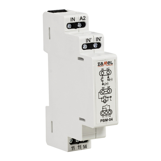
APPEARANCE
Tripping terminal (IN)
regulations
Tripping terminals (IN')
Relay output
terminals (11, 11, 14)
ZAMEL sp.j.
PBM-04/U
Tripping terminal: IN
Tripping rated voltage: 12 ÷ 230 V AC/DC
Supply voltage tolerance: -15 ÷ +10 %
Rated frequency: 50 / 60 Hz
Rated power consumption: 0 mA
Rated triggering power consumption: 11 mA
Relay contact parameters: 1NO - 10 A / 250 V AC1 2500 VA
Number of terminals: 7
Section of wire conductors: 0,2 ÷ 2,50 mm
Operating temperature: -20 ÷ +45
Operating position: optional
Fixing of the casing: TH35 rail (in accordance with PN-EN 60715)
Protection degree of casing: IP20 (PN-EN 60529)
Protection class: II
Overvoltage category: II
Degree of pollution: 2
Surge voltage: 1 kV (PN-EN 61000-4-5)
Dimensions: single module (17,5 mm) 90x17,5x66 mm
Weight: 0,065 kg
SERVICE MANUAL
2
C
o
PN-EN 60669-2-1
PN-EN 61000-4-2,3,4,5,6,11
Power supply terminal (A2)
VER. 001_04.08.2010
Advertisement

Related Manuals for Zamel Exta PBM-04/U


Summary of Contents for Zamel Exta PBM-04/U
- Page 1 Zakład Mechaniki i Elektroniki ZAMEL sp.j. J.W. Dzida, K. Łodzińska ul. Zielona 27, 43-200 Pszczyna, Poland Tel. +48 (32) 210 46 65, Fax +48 (32) 210 80 04 www.zamelcet.com, e-mail: marketing@zamel.pl DESCRIPTION TECHNICAL DATA PBM-04/U bi-stable relay is used to PBM-04/U...
- Page 2 4. ZMIE ZAMEL SP. J. is liable for processing any claim according to current Polish legislation. 5. ZMIE ZAMEL SP. J. shall process the claim at its own discretion: product repair, replacement or money return. 6. The manufacturer’s guarantee is valid in the Republic of Poland.
- Page 3 X-ON Electronics Authorized Distributor Click to view similar products for category: General Purpose Relays Other Similar products are found below : PCH124D2MH000 LY2ZDC24 FC3251 MJN1CAC24 MKS2XTIN11DC110 8501RS44V24 8501RSD14P14V51 8501XO40V02 G2RK112VDC 13932607...
Need help?
Do you have a question about the Exta PBM-04/U and is the answer not in the manual?
Questions and answers