
Related Manuals for Congatec conga-IC370


Summary of Contents for Congatec conga-IC370
- Page 1 Thin Mini-ITX SBC 8th Generation Intel Core i7, i5, i3 and Celeron Single Chip Ultra Low TDP U-Series SoC User's Guide Revision 1.2...
- Page 2 Updated tables 8 “Power Consumption Values” and 9 “CMOS Battery Power Consumption” • Official release • 2020-05-29 Added note about X20 USB 3.1 compliancy in section 5.4.1 “Rear USB 3.1 Gen Port” • 2020-07-03 Updated section 2.2 “Supported Operating Systems” Copyright © 2020 congatec AG ICWLm12 2/62...
- Page 3 In no event shall congatec AG be liable for any incidental, consequential, special, or exemplary damages, whether based on tort, contract or otherwise, arising out of or in connection with this user’s guide or any other information...
- Page 4 Copyright © 2020, congatec AG. All rights reserved. All text, pictures and graphics are protected by copyrights. No copying is permitted without written permission from congatec AG. congatec AG has made every attempt to ensure that the information in this document is accurate yet the information contained within is supplied “as-is”.
- Page 5 (c) arising from course of performance, course of dealing, or usage of trade. congatec AG shall in no event be liable to the end user for collateral or consequential damages of any kind. congatec shall not otherwise be liable for loss, damage or expense directly or indirectly arising from the use of the product or from any other cause.
- Page 6 Technical Support congatec AG technicians and engineers are committed to providing the best possible technical support for our customers so that our products can be easily used and implemented. We request that you first visit our website at www.congatec.com for the latest documentation, utilities and drivers, which have been made available to assist you.
-
Page 7: Table Of Contents
M.2 Key E Socket ..............29 5.12 CPU and System Fan Header ........... 51 5.2.5 PCI Express Routing ..............31 5.13 Sleep and Lid Button Header ..........52 Display Interfaces ..............32 5.14 External BIOS Flash ..............52 Copyright © 2020 congatec AG ICWLm12 7/62... - Page 8 6.7.4 OEM BIOS Code/Data ............. 58 6.7.5 OEM DXE Driver ..............58 Additional Features ..............54 congatec Battery Management Interface ........ 59 Micro-SIM Card ................ 54 API Support (CGOS) ..............59 Micro-SD Card ................. 55 6.10 Thermal and Voltage Monitoring ..........59 Security Features ..............
- Page 9 List of Tables Table 1 conga-IC370 Variants ............... 11 Table 37 X39, X40 Pinout Description ............ 47 Table 2 Cooling/IO Shield ..............11 Table 38 X41, X42 Pinout Description ............ 47 Table 3 Cables ..................12 Table 39 X56, X57 Pinout Description ............ 48 Table 4 Adapters ..................
-
Page 10: Introduction
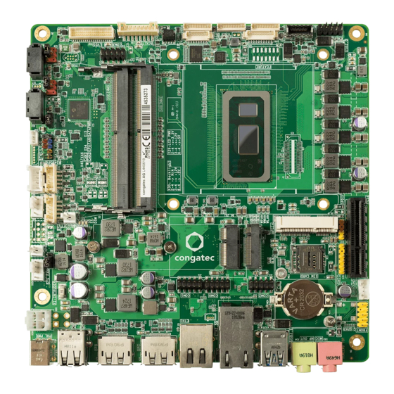
The conga-IC370 is a Single Board Computer designed based on the Thin Mini-ITX specification. The conga-IC370 features the 8th Generation Intel Core or Celeron U-Series processors. With 15 W base TDP, the SBC offers Ultra Low Power boards with high computing performance and outstanding graphics. -
Page 11: Options Information
Table 2 Cooling/IO Shield Accessories Part No. Description conga-IC97/CSA 052252 12 V active cooling solution with Thin Mini-ITX height (compatible with conga-IC370) conga-IC97/Retention Frame 052254 Retention frame for conga-IC97/CSA (compatible with conga-IC370) conga-IC370 IO Shield - Standard Size 053060 IO shield for conga-IC370 Mini-ITX height... -
Page 12: Table 3 Cables
LVDS adapter for variants with internal DP Table 5 Power Supply Part No. Description Power supply (90 W, 19 V @ 4.74 A) 10000146 FSP090-DIEBN2, Plug 7.4 x 5.1 x 12.5 mm Copyright © 2020 congatec AG ICWLm12 12/62... -
Page 13: Specification
Core™ i7,i5, i3 and Celeron Single Chip Ultra Low TDP Processors ® Memory Two memory sockets (located on the top side of the conga-IC370). Supports SO-DIMM non-ECC DDR4 modules Data rates up to 2400 MT/s Maximum 64 GB capacity (32 GB each) -
Page 14: Supported Operating Systems
CAN header Other Features Thermal and voltage monitoring CMOS Battery Beeper congatec standard BIOS (also possible to boot from an external BIOS flash) BIOS AMI Aptio ® V UEFI 2.6 firmware 32 MB serial SPI flash with congatec Embedded BIOS features Power ACPI 4.0 compliant with battery support. -
Page 15: Supply Voltage Power
SBC is powered by 12 V SBC is powered by 12 V Note 1. The fan and SATA drives were powered externally. 2. All other peripherals except the LCD monitor were disconnected before measurement. Copyright © 2020 congatec AG ICWLm12 15/62... -
Page 16: Supply Voltage Battery Power
Table 8 Power Consumption Values The table below provides additional information about the conga-IC370 power consumption. The values were recorded at various operating mode. Part Memory BIOS OS (64 bit) Current (A) Size Rev. Rev. Variant Cores Freq. /Max. Turbo S0: Min S0: Max S0: Peak S3... -
Page 17: Environmental Specifications
Operation: 0° to 60°C Storage: -20° to +70°C Humidity Operation: 10% to 90% Storage: 5% to 95% Note The above operating temperatures must be strictly adhered to at all times. Humidity specifications are for non-condensing conditions. Copyright © 2020 congatec AG ICWLm12 17/62... -
Page 18: Block Diagram
Board CAN Controller Tranceiver 8x GPIO Controller CAN Controller Tranceiver Agenda 8x GPIO Generation Optional Repeater I2C/SMB I2C/SMB (5V) SM Bus External I/O Repeater Front Panel 2x FAN RTC Battery Internal I/O Copyright © 2020 congatec AG ICWLm12 18/62... -
Page 19: Cooling Solution
Cooling Solution The conga-IC370 supports the cooling solutions listed in the table below. The dimensions of the cooling solutions are shown in the sub-sections. All measurements are in millimeters. Table 10 Cooling Solution Variants Cooling Solution Part No. Description congatec CSA... -
Page 20: Csa Dimensions
CSA Dimensions M3 screws for attaching cooling solution to retention frame Copyright © 2020 congatec AG ICWLm12 20/62... -
Page 21: Assembly Instruction
Assembly Instruction Follow the instructions below to securely attach a cooling solution to the conga-IC370: • Flip over the SBC and locate the position of the CPU. • Place retention frame on the bottom side of the board with insulating foil facing the PCB & standoffs inserted to mounting holes in PCB. -
Page 22: Connector Description
Connector Description Power Supply Connectors The conga-IC370 provides a DC power jack and a 4-pin Mini-Fit connector. The power input is protected by a 15 A non-resettable fuse. Note 1. We recommend a maximum input current of 8 A. 2. The conga-IC370 turns on immediately power is supplied. To change this default setting, enter the BIOS setup menu under “Boot Settings Configuration”... -
Page 23: Power Status Leds
Power Status LEDs The conga-IC370 provides onboard LEDs D66, D69 and D70 for power state indication. In addition, you can connect a bidirectional LED to pins 2 and 4 (FP_LED+ and FP_LED-) of the front panel connector X47 for power state indication. -
Page 24: Power-On Control Jumper
X61 : 1 x 3-pin, 2.5 mm pitch pin header 5.1.5 CMOS Battery Header The conga-IC370 provides a CR2032 CMOS battery which is attached to battery holder M24. The battery supplies power to maintain the CMOS settings and real time clock. Warning Danger of explosion if battery is incorrectly replaced. -
Page 25: Extension Sockets
• M.2 key E, type 2230 (PCIe x1/USB/CNVi) 5.2.1 PCIe x4 Socket The conga-IC370 provides a PCIe x4 socket (X8) for connecting PCIe x1, x2 or x4 cards. The socket supports PCIe Gen 3 (up to 8 GT/s per lane). Table 16 X8 Pinout Description... -
Page 26: Pcie Mini Card Socket
Connector Type X8: Standard PCIe x4 socket 5.2.2 PCIe Mini Card Socket The conga-IC370 provides a PCIe Mini Card socket (X9). The socket supports full or half size PCIe or USB 2.0 cards. Table 17 X9 Pinout Description Signal Signal WAKE# +3.3 V... - Page 27 +3.3 V +1.5 V +3.3 V Note The micro-SIM card slot (X11) can optionally be connected to these pins (assembly option). Connector Type X9: Standard Mini Card socket (full size or half size) Copyright © 2020 congatec AG ICWLm12 27/62...
-
Page 28: M.2 Key B Socket
5.2.3 M.2 Key B Socket The conga-IC370 provides an M.2 key B, type 2242/2280/3042 socket (X64) for connecting SSDs or WWAN (PCIe x2, SATA or USB) cards. Table 18 X64 Pinout Description Pin Signal Pin Signal CONFIG3 +3.3V +3.3V FULL_CARD_PWROFF#... -
Page 29: M.2 Key E Socket
Connector Type X64: Standard PCIe M.2 key B socket 5.2.4 M.2 Key E Socket The conga-IC370 provides an M.2 key E, type 2230 socket (X12) for connecting a PCIe, USB or Intel CNVi WLAN card. ® Table 19 X12 Pinout Description... - Page 30 PCIe0_Rx- COEX3 COEX2 REFCLK0+ COEX1 REFCLK0- SUSCLK PERST#0 CLKREQ0# BT_W_DISABLE#2 PEWAKE0# Wifi_W_DISABLE#1 CNV_WT_D1- CNV_WT_D1+ CNV_REFCLK CNV_WT_D0- PERST#1 CNV_WT_D0+ CNV_WT_CLK- +3.3 V CNV_WT_CLK+ +3.3 V Connector Type X12: Standard PCIe M.2 key E socket Copyright © 2020 congatec AG ICWLm12 30/62...
-
Page 31: Pci Express Routing
PCIe Lane 13 USB 2.0 Signals X12—M.2 key E (PCIe x1) PCIe Lane 14 USB 2.0 Signals X64—M.2 key B (PCIe x2) PCIe Lane 15 PCIe Lane 16 or SATA2 USB 2.0 Signals Copyright © 2020 congatec AG ICWLm12 31/62... -
Page 32: Display Interfaces
5.3.2 LVDS Header The conga-IC370 offers LVDS interface on X32. The LVDS source signals are shared with eDP interface on X27. The source signals are configured in the BIOS to support LVDS by default. The LVDS interface is on the top side of the SBC and it supports the following: •... -
Page 33: Table 20 X32 Pinout Description
2. The maximum output current for LCD and backlight power rails is 1.5 A. 3. Use ODD pins for single channel LVDS panel. 4. Use jumper X29 to set the LVDS panel voltage Copyright © 2020 congatec AG ICWLm12 33/62... -
Page 34: Embedded Displayport (Edp)
Embedded DisplayPort (eDP) The conga-IC370 provides eDP interface on X27. The eDP source signals are configured in the BIOS to support LVDS by default. For eDP support, go to Advanced -> Graphics -> Active LFP Configuration submenu in the BIOS setup menu and select “eDP”. -
Page 35: Panel Voltage Selection Jumper
Possible Mating connector: ACES 88441-40 or ACES 50204-40 5.3.4 Panel Voltage Selection Jumper The conga-IC370 supports 3.3 V, 5 V and 12 V LCD panels. Use jumper X29 to set the LVDS or eDP panel voltage. Table 22 X29 Pinout Description... -
Page 36: Backlight Power Connector
5.3.5 Backlight Power Connector The conga-IC370 provides backlight power connector X31. The maximum output current is 3 A. Table 23 X31 Pinout Description Signal Name Description BKLT_EN Backlight enable BKLT_CTRL Backlight control BKLT_PWR Backlight inverter power BKLT_PWR Backlight inverter power... -
Page 37: Backlight Power Selection Jumper
X30: 2.54 mm, 3 x 2-pin header (without pins 1 and 5) 5.3.7 Backlight Control Jumper The conga-IC370 supports LCD backlight control signals with 5 V or 3.3 V. Use jumper X65 to set the voltage level for pins 1 and 2 of the backlight power connector X31. Table 25... -
Page 38: Monitor Off Header
5.3.8 Monitor OFF Header The conga-IC370 provides monitor OFF header X28. Connect a momentary normally-open switch to X28, to switch on or switch off the backlight power of displays on LVDS or eDP connectors. Table 26 X28 Pinout Description Description... -
Page 39: Rear Usb 3.1 Gen 2 Port
5.4.1 Rear USB 3.1 Gen 2 Port The conga-IC370 provides two USB 3.1 Gen 2 ports on connector X20. Each port supports a maximum current of 1 A. Port 4 Port 3 Note 1. X20 ports (port 3 and 4) are only USB 3.1 Gen 1 compliant. -
Page 40: Internal Usb 2.0 Port
5.4.3 Internal USB 2.0 Port The conga-IC370 provides a USB 2.0 front panel header X21. The header supports two USB 2.0 ports. Each port supports a maximum current of 1 A. Table 27 X21 Pinout Description USB Port 7 USB Port 8... -
Page 41: Sata Connectors
Connector Type X23: 20-pin USB3.1 Internal Front Panel, Key-A SATA Connectors The conga-IC370 provides two standard SATA 3.0 ports, an M.2 key B socket and a SATA power header. 5.5.1 Standard SATA Port The conga-IC370 provides two standard SATA 3.0 ports (X13 and X16). The port supports: •... -
Page 42: M.2 Key B Socket
X64 pinout description. 5.5.3 SATA Power Header The conga-IC370 provides a 4-pin SATA power connector (X66) for 2.5” HDD or SSD. The header supplies 5 V or 12 V with a maximum current of 1.5 A. Table 28 X66 Pinout Description. -
Page 43: Ethernet
Ethernet The conga-IC370 provides one gigabit Ethernet (X5) and one 2.5 Gb Ethernet (X6). X5 interface is equipped with Intel i219-LM controller and supports Intel vPro/AMT technology. X6 interface is equipped with Intel i225-LM controller by default but can be equipped with Intel i255-V by assembly option. -
Page 44: Audio Connectors
Audio Connectors The conga-IC370 features a high definition audio codec (Realtek ALC888S). The signals are routed to internal and rear audio connectors. The rear connectors are Line-OUT and Mic-IN. The internal connectors are stereo speaker, digital microphone, SPDIF and front Panel HD audio. -
Page 45: Internal Audio
The conga-IC370 provides the stereo speaker, digital microphone, SPDIF and front panel HD audio connectors internally. 5.7.2.1 Stereo Speaker Header The conga-IC370 provides stereo speaker header X38. Each audio channel offers a maximum wattage of 6 W into 4 ohms. You can connect 4 ohm or 8 ohm stereo speakers to X38. Table 33... -
Page 46: S/Pdif Header
Connector Type X37: 2.54 mm, 1x 4-pin header (without pin 3) 5.7.2.4 Front Panel Header The conga-IC370 provides a front panel header X36. The header support line or headphone output, and microphone input. Table 36 X36 Pinout Description Pin Signal... -
Page 47: Com Port Headers
COM 1 and 2 (RS232/RS422/RS484) The LPC to UART bridge on the conga-IC370 provides two COM ports—COM 1 and COM 2 . COM port 1 provides RS232 COM port on pin header X39 or RS422/RS484 COM port on pin header X41. COM port 2 provides RS232 COM port on pin header X40 or RS422/484 COM port on pin header X42. -
Page 48: Com 3 And 4 (Rs232)
X56, X57: 2.54 mm, 2 x 5-pin headers GPIO Header The conga-IC370 provides GPIO headers X50 and X51. The GPIOs are sourced from the board controller. Each header offers eight GPIO signals and 3.3 V provided through a 500 mA resetable fuse. -
Page 49: I²C Bus/Sm Bus Header
Possible Mating Connector: Molex 0510211000 5.10 I²C Bus/SM Bus Header The conga-IC370 provides two pin headers (X43 and X52) for I²C/SM bus signals. Pin header X43 supports 5 V signal level while pin header X52 supports 3.3 V signal level. Table 41... -
Page 50: Front Panel Header
Front Panel Header The conga-IC370 provides pin header X47 for front panel features such as reset and power buttons, power state bidirectional LED and SATA LED. Pins 2 and 4 indicate the conga-IC370 power states. For LED status description, see section 5.1.3 “Power Status LEDs”. -
Page 51: Cpu And System Fan Header
CPU and System Fan Header The conga-IC370 provides pin header X54 for connecting CPU fan and pin header X55 for connecting system fan. The headers support 3-pin or 4-pin 12 V fan. The recommended maximum power rating for the fan is 4 W. -
Page 52: Sleep And Lid Button Header
External BIOS Flash With pin header X2, the conga-IC370 can boot from an external 3.3 V SPI flash. For external BIOS flash, you need a PCB adapter (with an SPI flash) that connects to X2. For more information, contact congatec support. -
Page 53: Chassis Intrusion Connector
5.15 Chassis Intrusion Connector The conga-IC370 provides pin header X1 for chassis intrusion detection. Connect normally-open switch to X1. Table 48 X1 Pinout Description Function INTRUDER# Connector Type X1: 2.54 mm, 2-pin connector (Molex 22-27-2021) 5.16 Feature Header The conga-IC370 provides pin header X44 for various functions. -
Page 54: Additional Features
Additional Features Micro-SIM Card The conga-IC370 offers a top-entry micro-SIM slot X11 for inserting SIM card. Table 50 X11 Pinout Description Signal Description Power Reset Clock Not available Ground Not connected Data Not available Note 1. The micro-SIM card slot is connected to M.2 key B socket X64 by default. -
Page 55: Micro-Sd Card
Micro-SD Card The conga-IC370 offers a micro-SD slot on X53. The SD card slot complies with SDXC card specification 3.01 with support for up to 104 MBps data rate. The slot is located at the bottom-side. Table 51 X53 Pinout Description... -
Page 56: Optional Can Header
The conga-IC370 is equipped with a Microchip MEC1705 microcontroller. This onboard microcontroller plays an important role for most of the congatec BIOS features. It fully isolates some of the embedded features such as system monitoring, I²C bus from the x86 core architecture. The isolation helps improve performance and reliability even when the x86 processor is in a low power mode. -
Page 57: Power Loss Control
OEM BIOS Customization The conga-IC370 is equipped with congatec Embedded BIOS, which is based on American Megatrends Inc. Aptio UEFI firmware. The congatec Embedded BIOS allows system designers to modify the BIOS. For more information about customizing the congatec Embedded BIOS, refer to the congatec System Utility user’s guide CGUTLm1x.pdf on the congatec website at www.congatec.com or contact technical support. -
Page 58: Oem Boot Logo
OEM POST Logo This feature allows system designers to replace the congatec POST logo displayed in the upper left corner of the screen during BIOS POST with their own BIOS POST logo. Use the congatec system utility CGUTIL 1.5.4 or later to replace or add the OEM POST logo. -
Page 59: Congatec Battery Management Interface
The architecture of the CGOS API driver provides the ability to write application software that runs unmodified on all congatec CPU modules. All the hardware related code is contained within the congatec embedded BIOS on the module. See section 1.1 of the CGOS API software developers guide, available on the congatec website. -
Page 60: Mechanical Drawing
BKLT PWR JP PANEL VOLT. JP RS422/484 COM 1 MONITOR OFF COM 4 M.2 KEY B SOCKET M.2 KEY E SOCKET PCIE MINI CARD DMIC S/PDIF PCIE x4 FRONT PANEL SPKR 10.16 154.94 Copyright © 2020 congatec AG ICWLm12 60/62... -
Page 61: Bios Setup Description
BIOS Setup Description The BIOS setup description of the conga-IC370 can be viewed without having access to the module. However, access to the restricted area of the congatec website is required in order to download the necessary tool (CgMlfViewer) and Menu Layout File (MLF). -
Page 62: Updating The Bios
BIOS updates are recommeded to correct platform issues or enhance the feature set of the module. The conga-IC370 features a congatec/AMI AptioEFI firmware on an onboard flash ROM chip. You can update the firmware with the congatec System Utility. The utility has five versions—...
Need help?
Do you have a question about the conga-IC370 and is the answer not in the manual?
Questions and answers