Table of Contents
Advertisement
Available languages
Available languages
Quick Links
INSTRUCTION
EN
ARGUS-RC-H
i
Read this instruction before installation
and wiring of the product
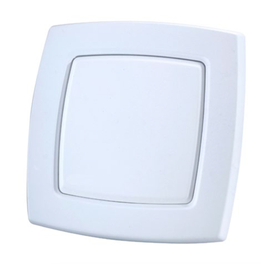
Room controller
Argus-RC-H is a room controller from the Argus series, intended to
control heating and cooling in a zone control system. Installation is
directly on the wall or on an electrical connection box. The controller
does not have a communication connection.
Technical data
Supply voltage
18...30 V AC, 50...60 Hz
Internal consumption
2.5 VA
Ambient temperature
0...50°C
Ambient humidity
Max 90% RH
Storage temperature
-20...+70°C
Built-in temperature sensor NTC Type, range 0...50°C, accuracy
+/-0.5°C at 15...30°C
Inputs and outputs
Refer to connection illustrations and
table below
Connection terminals
Lift type for cable cross-section 2.1 mm
Protection class
IP20
Material, casing
Polycarbonate, PC
Weight
110 g
Dimensions
95 x 95 x 28 mm
Place the controller in a location that has a temperature representative for
the room. A suitable location is approx. 1.6 m above floor level in a place
with unobstructed air circulation.
Remove the frame by depressing the locking tab in the lower edge of the
cover with a screwdriver. See figure 1.
Then prize out the electronics cassette using the four rectangular screwdri-
ver slots and levering against the edge of the bottom plate. See figure 2.
Note: Take care not to damage the electronics when inserting the screw-
driver into the slots.
Figure 1
The bottom plate with terminals has a number of fixing hole combina-
tions. Select suitable holes (see figure 3) and screw the bottom plate onto
the wall or connection box, so that the arrows on the bottom plate point
upwards. Do not tighten the screws too hard!
With surface-mounted cabling, break-out suitable holes from the marks in
the plastic.
60
Figure 3. Bottom plate with mounting alternatives and location of
terminals (dimensions in mm.)
2
ARGUS-RC-H
°C
°C
Figure 4. Connection diagram for Argus-RC-H
Figure 2
Figure 5. Alternative connection for terminals 31, UI1, and terminal
33, DI2/CI, terminal 23, UO1, and terminal 24, UO2.
68
Follow table 1 below for setting. (FS) in the text indicates factory set-
ting.
Table 1. I/O connection terminals
Ter-
minal
10
11
12
13-14
30
AI1
G
10
31
UI1
G0
11
32
DI1
DO1
12
33
DI2/CI
-
13
-
14
40
+C
GDO
20
41
AGnd
G0
21
42
-
-
22
43
-
UO1
23
UO2
24
30
AI1
G
10
31
UI1
G0
11
32
DI1
DO1
12
33
DI2/CI
-
13
-
14
40
+C
GDO
20
41
AGnd
G0
21
42
-
-
22
43
-
UO1
23
UO2
24
Desig-
Operation
nation
G
Supply voltage 24 V AC
G0
Supply voltage 0 V
DO1
For forced ventilation. 24 V AC output, max 0.5 A.
24 V AC actuator is connected between terminal
12 and terminal 20, GDO.
No function
24 V AC
G0
G
G
G0
Y
G
G0
Y
1
Advertisement
Table of Contents

Related Manuals for SystemAir ARGUS-RC-H


Summary of Contents for SystemAir ARGUS-RC-H
- Page 1 AGnd Room controller the plastic. Argus-RC-H is a room controller from the Argus series, intended to control heating and cooling in a zone control system. Installation is directly on the wall or on an electrical connection box. The controller does not have a communication connection.
- Page 2 This setting is used when UO1 is connected to a thermal actuator of type RTAOM-24 (NO). In the event of a power AGnd Analogue ground, reference for AI and UI (with cut the valve will open. analogue and digital function) ARGUS-RC-H...
- Page 3 The Läs denna instruktion innan produkten Argus-RC-H has control state: Heating and cooling in sequence. The controller's control setpoint is the same as the current setpoint plus/minus change-over function can be activated, see below.
- Page 4 11, G0. korrekt plint på ställdonet. Ingen funktion alternativt Figur 4. Inkopplingsschema för Argus-RC-H För 24 V AC termiskt ställdon, max 2,0 A. Det termiska ställdonet ansluts mellan plint 24 och 20, GDO. Val av utgångsfunktion, analog eller digital, se tabell 3, SW6.
- Page 5 Regulatorns regler- av SW1-8. (FI) i texten innebär fabriksinställt värde. Argus-RC-H har reglerfall: Värme och kyla i sekvens. Change-over funk- börvärde är lika med aktuellt driftläges börvärde plus/minus lokal tion kan aktiveras, se nedan.
- Page 6 Produkten uppfyller kraven för gällande europeiska LVD-standard IEC 60 730-1. Régulateur d’ambiance Kontakt Argus-RC-H est un régulateur d’ambiance de la gamme Argus qui permet Systemair AB, 739 39 Skinnskatteberg, Sweden Figure 1 Figure 2 de réguler le chauffage et le refroidissement dans les systèmes de Tel: +46 222 440 00, Fax: +46 222 440 99 contrôle de zones.
- Page 7 Voir les tableaux 2 et 3 pour le réglage de SW1-8. «RU» bornes 24 et 20 (GDO). indique le réglage d’usine. Pour plus de détails sur la sélection du type de sortie, analogique ou digitale, voir tableau 3 (SW6). ARGUS-RC-H...
- Page 8 Valeur de consigne Modes de régulation Le chauffage et le refroidissement sont arrêtés. par défaut (°C) Argus-RC-H a deux modes de régulation : chauffage et refroidissement en séquence. Il y a aussi une fonction change-over (voir ci-dessous). Valeur de consigne 22 (RU) La valeur de consigne peut être ajustée de +/- 3°C grâce à...
Need help?
Do you have a question about the ARGUS-RC-H and is the answer not in the manual?
Questions and answers