
Subscribe to Our Youtube Channel
Related Manuals for powersoft DSP-Lite


Summary of Contents for powersoft DSP-Lite
- Page 1 DSP-Lite USER GUIDE ©2020 Powersoft Keep this manual DO000203.01 R00 for future reference...
- Page 2 Para obter atualizações, consulte a versão em Inglês disponível online em www.powersoft-audio.com. Designed in Italy by Powersoft S.p.A. (via E. Conti, 5 - 50018 Scandicci, Firenze) Factory 1: MW.FEP S.p.A. (Via Modena, 68 - 40017 San Giovanni in Persiceto, Bologna - Italy)
-
Page 3: Table Of Contents
11 : 1.1. DSP-Lite ETH 11 : 1.2. DSP-Lite USB 5. Mechanical drawings 11 : 2.Routing presets 5 : 1.How to fit the mounting plate to the DSP-Lite processing 12. Processing architecture board 5 : 2.Components 12 : 1.Input processing 6. - Page 4 Page intentionally left blank 2 | DSP-Lite...
-
Page 5: Dsp-Lite
DSP-Lite processing board. inspected before leaving the factory. Carefully inspect the We know you are eager to use the DSP-Lite board, but shipping package before opening it, and then immediately please take a moment to read this user’s manual and safety inspect your new product. -
Page 6: Important Safety Instructions
8. Do not defeat the safety purpose of the polarized or grounding- Symbol for earth/ground connection. type plug. 9. Only use attachments/accessories specified by Powersoft. Symbol for conformity with Directive 2002/96/EC 10. Refer all servicing to qualified service personnel. Servicing is... -
Page 7: Regulatory Information
For compliance questions only: compliance@powersoft.it vironment. Powersoft S.p.A. comply with the Directive 2002/96/EC and 2003/108/EC of the European Parliament on waste electrical finance the cost of treatment and recovery of electronic equipment (WEEE) in order to reduce the amount of WEEE that is being disposed of in land-fill site. -
Page 8: Mechanical Drawings
N. 2 HOLES 36,5 36,5 FIG. 1: DSP-Lite (all dimensions in millimetres). General Tolerance = UNI-ISO 2768-M DSPLE004 DSPLE004 5 : 1.How to fit the mounting plate to the DSP-Lite processing board N. 4 HOLES TILT REV. DATE REV. DATE... -
Page 9: 2.Components
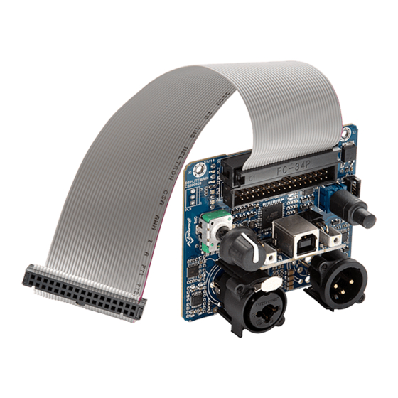
Input signal connector Jack - XLR Volume potentiometer Molex Optional LEDs connector 22-01-2031 Status LED Signal presence / limiting Signal clipping / temperature *Stereo versions only CB000601.00 FIG. 2: Example of connection: DSP-Lite with LiteMod amp module. 43.5 DSP-Lite | 7... -
Page 10: Mounting Kit For Digimod Heatsink Plate
Mounting kit for DigiMod heatsink plate Available for DSP-L USB and ETH KTDSPL01 kit DSP-Lite for DigiMod heat sink N. 4 HOLES Code Quantity Description ME001049.00.00 DSP-Lite shield 78x126 mm DSPL0001 DSP-Lite processing board ME001036.00.01 DSP-Lite Aluminium plate 78x126 mm... -
Page 11: Mounting Kit For Litemod Heatsink Plate
Mounting kit for LiteMod heatsink plate Only available for DSP-L USB 43,5 N. 4 HOLES (*) General Tolerance = UNI-ISO 2768-M DSP-Lite | 9... -
Page 12: Connections
Connections 7 : 1.PL2 connector This connector interfaces the DSP-Lite to Powersoft amp modules featuring the IDC 34 pin connector. The PL2 connector is the default input/output connector, meant to be used in two-channel applications or for driving the MF & HF ways in three-channel applications. - Page 13 Absolute Max output Channel 2 OUT 2 + 27 � Positive Balanced output Balanced 4.1 V Absolute Max output Ground RESERVED RESERVED RESERVED Active High, SDPWS 10 � Power Supply Shut Down Logic output 0-5 V DSP-Lite | 11...
-
Page 14: 1.Pl3 Connector
(40 mA max current draw) Active Low, CH3 and CH4 MUTE pulled to GND Output Stage Mute +VCCMON +7.5 V Rail Bus Positive Monitor -VCCMON –7.5 V Rail Bus Negative Monitor Table continues on the next page... 12 | DSP-Lite... - Page 15 Positive Balanced Output OUT 4 + 27 � Balanced (same as pin 6) 4.1 V Absolute Max output Ground RESERVED RESERVED RESERVED Active High, SDPWS 10 � Power Supply Shut Down Logic output 0-5 V DSP-Lite | 13...
-
Page 16: 2.Pl4 Pinout
CYAN System ready to play, auto standby mode enabled Sleeve System in standby mode: no signal detected in the latest COLD BLUE 15 minutes Analog line output XLR-F pinout Pin 1 Pin 2 Pin 3 COLD COLD 14 | DSP-Lite... -
Page 17: Power Management
FIG. 4: Unit embedding DSP-L discovered. supply. By default the deep sleep mode is not active. In order to activate this feature (only available for LiteMod amp module) the J2 jumper on the rear surface of the DSP-Lite PCB must be shorted. 15 | DSP-Lite... - Page 18 11 : 1.1.1. Changing Network Settings Drag and drop the DSP-Lite ETH just discovered and double click on it for entering inside the processing. Network Settings section is available by click on button in the scheme view. Here you can get the current ethernet status and change address settings.
-
Page 19: 1.2. Dsp-Lite Usb
11 : 1.2. DSP-Lite USB In order to access the DSP via the USB port of your computer, the CP210x USB to UART Bridge Virtual COM Port (VCP) drivers are required. Freely download the drivers from the Silicon Labs website: www.silabs.com > Products > USB bridge >... -
Page 20: 2.Routing Presets
CH3 and CH4 signal lines with the same signal, forcing Armonía Pro Audio Suite provides four routing preset either a bridge mode configuration (see specific power for the DSP-Lite processing board. These presets shall be module BTL connection) or a “clone” configuration (two loaded BEFORE configuring the signal processing. -
Page 21: Processing Architecture
Processing architecture FIG. 6 displays the block diagram of the DSP-Lite f Equalizer: specifications changes according to preset, hardware architecture. The signal processing layout can be TAB. 2 summarized in three blocks: f RMS Limiter: frequency dependent limiter with 2 f Input processing;... - Page 22 Output 2 processing processing LIMITER 170ms Output 3 MONO CLIP Output POTENTIOMETER processing LIMITER Output 4 cliping Temperature GAIN (5 bands) Input processing OUTPUT EQ / XOVER PEAK GAIN DELAY LIMITER LIMITER (8-11 bands) 10ms Output processing 20 | DSP-Lite...
-
Page 23: Specifications
2 IN 115 dB (A weighted) OUT 1&2 114 dB (A weighted) Dynamic range DA OUT 3 102 dB (A weighted) Power requirement +12 V 250 mA max current draw -12 V 40 mA max current draw 21 | DSP-Lite... -
Page 24: Appendix
A.1. Note on J3 and J4 jumpers J3 and J4 jumper on the rear surface of the DSP-Lite remove PCB are directly connected to the front R7 and R53 resis- tors respectively. - Page 26 Powersoft S.p.A. Via Enrico Conti, 5 50018 Scandicci (FI) Italy Tel: +39 055 735 0230 Fax: +39 055 735 6235 Sales & general inquiries: sales@powersoft.it Application & technical support: support@powersoft.it Service & maintenance: service@powersoft.it Compliance requests: compliance@powersoft.it powersoft-audio.com...
Need help?
Do you have a question about the DSP-Lite and is the answer not in the manual?
Questions and answers