Table of Contents
Advertisement
USER MANUAL FOR STANDARD F200 ANALYZER
Manufactured by
Head office
C-4th&5th, 16, Deogyeong-daero 1556beon-gil, Yeongtong-gu, Suwon-si, Gyeonggi-do, 16690, REPUBLIC OF KOREA
Manufacturing site
74, Osongsaengmyeong 4-ro, Osong-eup, Heungdeok-gu, Cheongju-si, Chungcheongbuk-do, 28161, REPUBLIC OF KOREA
+82-31-300-0400
+82-31-300-0499
sales@sdbiosensor.com
www.sdbiosensor.com
Advertisement
Table of Contents

Subscribe to Our Youtube Channel
Related Manuals for SD Biosensor F200


Summary of Contents for SD Biosensor F200
- Page 1 USER MANUAL FOR STANDARD F200 ANALYZER Manufactured by Head office C-4th&5th, 16, Deogyeong-daero 1556beon-gil, Yeongtong-gu, Suwon-si, Gyeonggi-do, 16690, REPUBLIC OF KOREA Manufacturing site 74, Osongsaengmyeong 4-ro, Osong-eup, Heungdeok-gu, Cheongju-si, Chungcheongbuk-do, 28161, REPUBLIC OF KOREA +82-31-300-0400 +82-31-300-0499 sales@sdbiosensor.com www.sdbiosensor.com...
- Page 3 STANDARD Thank you for your purchase of the STANDARD F200 Analyzer This user manual contains all the information needed to use the analyzer and keep it ready to operate. Please read this user manual carefully before using the analyzer. Familiarize yourself with the required preparations and the measurement procedure before performing the first measurement.
- Page 4 TABLE OF CONTENTS CHAPTER 01. General Information ............... 6 Main Menu Structure ................6 Symbol and Abbreviation ..............10 Brief Precautions and Limitations ............12 CHAPTER 02. Introduction ................13 Intended Use ..................13 Product Description ................13 Before You Start Testing ................13 Specifications..................15 CHAPTER 03.
- Page 5 CHAPTER 08. Screen Messages and Troubleshooting ......55 Warning Messages ................55 Error Messages ..................57 ANNEX 01. Information for Healthcare Professionals ......60 Protection against Infections ..............60 Electromagnetic Compatibility .............60 ANNEX 02. Reference ................61...
- Page 6 CHAPTER 01. General Information Main Menu Structure Main Menu Standard Read Review Test Only Patient Calibration Login Login Result Result Result Detailed Insert Insert Search Result Device Device Send Device Device Select Result Check Check Apply Select All Analyze Sample Sample Delete Finish...
- Page 7 Calibration Supervisor Password Login Login Insert Insert Manage Load/ Update Device Device Operator Save Device Eject Setting Info Check Device Apply Insert Sample Device Sample Eject Check Device Insert Analyze Device Analyze Finish Finish...
- Page 8 Send Results Manage Operator Send Unsent Results Send All Results Edit Send All QC Results Delete Send Last Reults Send All Patients Results Send Selected Results Load / Save Settings Load Save Load Save Operator ID Save Test Records Update Info S/W Update View Version...
- Page 9 Settings Set Print Option Set Timeout Set Calibration and QC Date/Time Language General Settings Units Network Volume/ Instrument Name Parameters Brightness...
- Page 10 Symbol and Abbreviation The symbols and abbreviations may appear on the packaging, on the labels, and in the instructions for the STANDARD F200 Analyzer. Symbol Symbol Description Manufacturer In vitro diagnostic medical device Intended to use outside the body Consult instructions for use...
- Page 11 Abbreviation Abbreviation Description Communication Comm Laboratory Information System Hospital Information System Graphic User Interface Software Firmware...
- Page 12 Brief Precautions and Limitations To reduce the risk of analyzer damage · For in vitro diagnostic use. · Keep the STANDARD F200 Analyzer on a flat and dry surface Caution and avoid direct sunlight when operating. · The analyzer has internal correction for normal levels of...
- Page 13 Product Description The STANDARD F200 Analyzer can read the lot of the specific test devices in use by checking their 2D barcodes. While the test device is inserted into the STANDARD F200 Analyzer, the application well of the test device would be illuminated by UV or RGB LED (light-emitting diode) with scanning.
- Page 14 Samples The STANDARD F200 Analyzer should be only used the specific test devices for the analyzer. Because specimens are quite different for each parameter, follow the instructions from the each test device instructions. Safety Information There is a potential risk of infection. We recommend that healthcare professionals using the STANDARD F200 Analyzer to perform measurements for more than one patient use gloves and follow all other locally applicable health and safety regulations.
- Page 15 HL7 PCD-01 Profile Support LIS/HIS 200 x 240 x 205 mm Size Manual Labeling Contents · STANDARD F200 Analyzer · STANDARD F Calibration Set Materials required but not provided · STANDARD F Test Device · 12V/5A AC/DC Power adaptor · USB Barcode scanner...
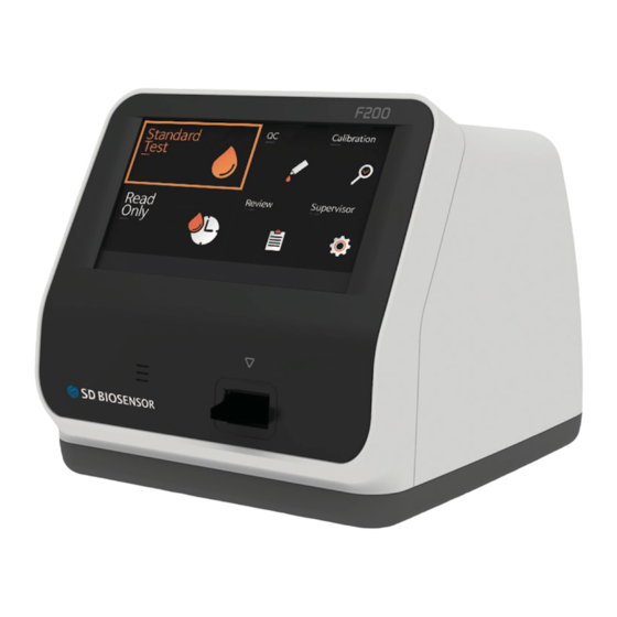
- Page 16 Overview of STANDARD F200 Analyzer...
- Page 17 Use for upgrading the F/W upgrade by PC connection K. Additional Device Port Use for connecting with specific device manufactured by SD BIOSENSOR,Inc. Accessories of the STANDARD F200 Analyzer Accessory STANDARD F Calibration Set F CAL-1, F CAL-2, F CAL-3...
- Page 18 CHAPTER 03. Setting and Performing Operating the Analyzer STEP 1. Connect AC/DC adaptor jack 1-1. Place the analyzer on the bench top within reach of an electrical outlet. The unit is portable and can be moved to a suitable location for testing.
- Page 19 1st step: Entering set mode 1. First, touch the 'Supervisor' on the screen in the main menu to enter the set mode and proceed the test. 2. Input the password and press the ‘OK’ for entry. Initial password is 0000. Press the ‘Cancel’...
- Page 20 2nd step: Supervisor>Manage operator 1. Select the ‘Manage Operator’ on the screen to add, edit or delete operator ID. Press the ‘Back’ if you want to return to previous setting. 2. To add operator ID, press 'Add'. Also, use the touch panel keyboard or USB connected keyboard to add the operator ID.
- Page 21 4. To edit the a name of the operator currently registered in the analyzer, select the operator ID you want to edit and press ‘Edit’. After editing, Press ‘OK’ to confirm. 5. To delete the name of the operator currently registered in the analyzer, select the operator ID you want to delete and press ‘Delete’.
- Page 22 3rd step: Supervisor > Load/Save The software including GUI can be updated by USB memory, and the firmware can be updated by mini USB with PC connection. The USB can be connected at any time with the analyzer’s power on. Note 1.
- Page 23 3. When the procedure of loading data is completed, the screen will promptly show the message that the data has loaded successfully. Then press ‘OK’ to confirm. 4. To save the analyzer setting data that clone or duplicate the setting of the first, press ‘Save’.
- Page 24 6. When the procedure of loading operator ID is completed, the screen will promptly show the message that the operator ID has loaded successfully. Then press ‘OK’ to confirm. 7. In addition, the operator can save the operator ID by pressing ‘Save’. When the the procedure of saving operator ID is completed, press ‘OK’...
- Page 25 4th step: Supervisor > Update FIRMWARE UPDATE PROCEDURE PROCEDURE FOR THE COMPUTER PROCEDURE FOR THE F200 1. Run firmware update program ‘F200FirmwareUpdater_X_X.exe’. 2. Select menu button on the F200 LCD screen to firmware update. <Select the ‘Supervisor’> <Enter the password ‘0000’>...
- Page 26 <Select the ‘Update’> <Select the ‘F/W Update’> <Select the ‘OK’> <Connect ‘Mini-5pin USB cable’ to computer and F200 Analyzer>...
- Page 27 <Push the ‘Upgrade Firmware’ button once it is activated> <Push the ‘OK’ button> <F200 Firmware update is completed>...
- Page 28 2. Connecting USB memory to the F200 analyzer 1) Connect USB memory to the USB port on the F200 analyzer. 2) The USB image will be displayed on the LCD screen of F200 analyzer. 3. Updating F200 analyzer’s software 1) Select the ‘Supervisor’ menu on the screen.
- Page 29 3) Select the ‘Update’ menu. 4) Select the ’S/W Update’ menu. 5) Press the ‘OK’ button. 6) Software update will finish automatically. 7) Once the S/W update is completed, F 200 shuts down automatically. Please turn on again to start using F200.
- Page 30 5th: Supervisor > Settings 1. To set the print option, automatic turn-off time, calibration and QC period, general settings or instrument name, enter the ‘Settings’ menu. Press ‘Back’ to return to the previous menu. 2. To set the numbers of printed sheet in 1, 2 and auto-printing mode (ON/OFF) enter the ‘Set Print Option’...
- Page 31 3. To control the analyzer's automatic turn-off time for power saving, enter the ‘Set Timeout’ menu. Insert test device stage procedure means that the user doesn't any action after inserting test device to the analyzer, and then the test is finished. Standby mode means the user doesn't any action even inserting test device into the analyzer.
- Page 32 5. To set the date/time, language, test parameter's unit, network, LIS parameter, sound volume, or LCD brightness, enter the ‘General Settings’ menu. Especially, in case unit setting, the analyzer is capable of setting test parameters corresponding to test type and the parameters can be adjusted larger by updating of analyzer software.
- Page 33 <Setting the test parameter's unit> <Setting the network> <Setting the LIS parameter> It is recommended to consult with the technician as for the setting the network or the LIS parameter. Note...
- Page 34 <Setting the sound volume/LCD brightness> <Setting the instrument name>...
- Page 35 6th: Supervisor > Info 1. To display and view the analyzer's current version of software, firmware or network, enter the ‘Info’ menu. 2. When selecting ‘View Version’, the version information of the software and firmware will be displayed. Press ‘OK’ to confirm.
- Page 36 3. When selecting ‘View Network’, the information of the network will be displayed. Press ‘OK’ to confirm.
- Page 37 Performing a Measurement Check the following before performing the measurement: · Is the analyzer connected with AC/DC adaptor? · Are date and time correct? · Have you checked the analyzer's setting? Select the Desired Test Mode Standard Test Mode may be most convenient for reading a single patient sample, as the user can standard test during the development period.
- Page 38 3. Once the ‘Insert Device’ is displayed on the screen, insert the specified test device into the analyzer’s test slot. 4. When inserting the test device to the analyzer, the analyzer will automatically check whether it is used or not. Also, the analyzer will read the barcode data and check the test device is valid to start the test.
- Page 39 6. The test device is developed in the analyzer. The time for development depends on the type of the test device. 7. Then, the analyzer will automatically scan and analyze the test results. The scanning times can vary with the type of the test device. 8.
- Page 40 9. When pressing ‘OK’, 'Eject Device' message will be displayed. Then, you should remove the test device from the analyzer. 10. When test device is ejected, the analyzer will move to another test log-in menu to perform the next test. Press ‘Cancel’ at any procedure to quit the ongoing test progress.
- Page 41 2. Input operator ID, patient ID, and order #. The operator ID can also be input with the barcode scanner. If the ID is not input into the analyzer with touching 'Direct', the analyzer will regard the test as that of the guest. 3.
- Page 42 4. When the timer goes off for test device #1, then insert test device #1 into the analyzer, the analyzer will display the result in approximately ten seconds. 5. When inserting the test device to the analyzer, the analyzer will automatically check whether it is used or not.
- Page 43 7. When pressing ‘OK’, 'Eject Device' message will be displayed. Then, you should remove the test device from the analyzer. 8. When test device is ejected, the analyzer will move to another test log-in menu to perform the next test. Press ‘Cancel’ at any procedure to quit the ongoing test progress.
- Page 44 Data Transfer Displaying Stored Measured Values 1. The STANDARD F200 Analyzer has 3000 measured memories together with date, time and flags allowing you to review them in order from the most recent to the oldest. When the memory is full and a new result is added, the analyzer will delete out the oldest one.
- Page 45 Send Results 1. Among several ways to send the test result, you can choose the proper way to communicate with data server. <Sending the unsent results> <Sending the last results>...
- Page 46 <Sending all results> <Sending selected results>...
- Page 47 CHAPTER 05. Quality Control Control Test It is important to perform control tests with more than one level of control to assure your system is working properly and your testing technique is good. When to use the control · Using the analyzer for the first time. ·...
- Page 48 2. Once the ‘Insert Device' is displayed on the screen, insert the specified test device into the analyzer’s test slot. 3. When inserting the test device to the analyzer, the analyzer will automatically check whether it is unused or not. Also, the analyzer will read the barcode data and check the test device is valid to start the test.
- Page 49 5. The test device is developed in the analyzer. 6. Then, the analyzer will automatically scan and analyze the test results. 7. Once the development time is finished, the test results will be displayed. Also, the analyzer will be able to print out the test results when auto-printing is on.
- Page 50 8. After the procedure of analyzing the test device is completed, 'Eject Device' message will be displayed. Then, you should remove the test device from the analyzer.
- Page 51 CHAPTER 06. Calibration Set Calibration Set Test Calibration set test is the required function that ensures optimal performance by checking the designated method. When to use calibration set · Whenever the analyzer is powered on. · When you drop the analyzer. ·...
- Page 52 2. Once the ‘Insert Device’ is displayed on the screen, insert the CAL-1 into the analyzer’s test slot. 3. When inserting the test device to the analyzer, the analyzer will automatically check whether the CAL-1 is used or not. Additionally, the analyzer will read the barcode data and check the device is valid to start the calibration set test.
- Page 53 5. Insert CAL-3 for RGB-LED testing. Ensure that insert CAL-2 and CAL-3 in order. Never change the order. 6. If measured value is within the normal range, ‘OK’ message will be displayed on the screen. 7. If measured value is not within the normal range, ‘EEE’ message will be displayed on the screen.
- Page 54 CHAPTER 07. Cleaning and Maintenance Cleaning the Analyzer To prevent malfunction of the analyzer, keep the test slot free from specimen moisture or dust. Use lint-free cloths. For cleaning, there are suitable solutions such as mild suds, 70 % ethanol or isopropyl alcohol. At the professional case (e.g.doctor’s surgery), a mixture of 1-propanol, 2-propanol and glutaraldehyde is recommended.
- Page 55 CHAPTER 08. Screen Messages and Troubleshooting Warning Messages Indication Warning description Warning: Operator ID Press ‘OK’ not entering the operator's ID. Solution Enter the operator's ID First, and then press ‘OK’ Warning: Not connected USB Not inserting USB. Solution Confirm USB is inserted correctly. Warning: Password Entering incorrect password of supervisor.
- Page 56 Indication Warning description Warning: Review Not selecting in review data list. Solution Press ‘Send selected result’ after selecting the result. Warning: Unregistered Operator ID Entered operator ID does not be registered. Solution Add operator ID in set mode. Warning: Out of Paper There is no printer paper in analyzer.
- Page 57 Error Messages Indication Error description E01: Test Device Error The test device is damaged or inserted improperly. Solution Discard the test device and re-test with a new test device and a new specimen. E02: Blood Specimen Error An insufficient blood has been applied. Solution Re-test with the new test device with an enough specimen, ensuring that blood is...
- Page 58 Solution This error occurs with a specimen known to have total hemoglobin in the abnormal range. If the error continues after turning ON/OFF the analyzer, please contact SD BIOSENSOR, Inc. Result: Extremely Low C line The test is invalid. Solution Re-test with the new test device and the new patient's specimen.
- Page 59 Error description E12: Calibration Overdue The calibration is overdue. Solution If the error continues after turning ON/OFF the analyzer, please contact SD BIOSENSOR, Inc. E13: Not Supported Test Device Loading test device is not proper for the analyzer. Solution Check the type of the test device whether it is manufactured by SD Biosensor, Inc.
- Page 60 Professionals Protection against Infections There is a potential risk of infection. Medical staff using the STANDARD F200 Analyzer to perform measurements for more than one patient must be aware that any object coming into contact with human specimen is a potential source of infection.
- Page 61 ANNEX 02. Reference 1. American Diabetes Association, Clinical Practice Recommendation Guidelines 2003, Diabetes care, Vol. 26. Supplement 1. p.22. 2. Stedman, TL. Stedman’s Medical Dictionary, 27th Edition, 1999, p. 2082. 3. Ellen T. Chen, James H. Nichols, Show-Hong Duh, Glen Hortin, MD: Diabetes Technology &...
- Page 62 Disposal The STANDARD F200 Analyzer must be disposed according to the local regulations concerning the disposal of electrical and electronic equipment. The Waste Electrical and Electronic Equipment (WEEE) regulation implement provisions of the European Parliament and Council Directive 2002/96/EC ailmed to reducing the amount of EEE waste going for final disposal.
- Page 63 NOTE...
- Page 64 MT Promedt Consulting GmbH Altenhofstrasse 80 D-66386 St. Ingbert Germany Phone : +49 6894 581020, Fax : +49 6894 581021 Manufactured by SD Biosensor, Inc. Head Office C-4th&5th, 16, Deogyeong-daero 1556beon-gil, Yeongtong-gu, Suwon-si, Gyeonggi-do, 16690, REPUBLIC OF KOREA Manufacturing Site...
Need help?
Do you have a question about the F200 and is the answer not in the manual?
Questions and answers