Table of Contents
Advertisement
STANDARD F100 ANALYZER USER MANUAL
Manufactured by
Head office
C-4th&5th, 16, Deogyeong-daero, 1556beon-gil, Yeongtong-gu, Suwon-si, Gyeonggi-do, 16690, REPUBLIC OF KOREA
Manufacturing site
74, Osongsaengmyeong 4-ro, Osong-eup, Heungdeok-gu, Cheongju-si, Chungcheongbuk-do, 28161, REPUBLIC OF KOREA
+82-31-300-0400
+82-31-300-0499
sales@sdbiosensor.com
www.sdbiosensor.com
Advertisement
Table of Contents

Related Manuals for SD Biosensor F100


Summary of Contents for SD Biosensor F100
- Page 1 STANDARD F100 ANALYZER USER MANUAL Manufactured by Head office C-4th&5th, 16, Deogyeong-daero, 1556beon-gil, Yeongtong-gu, Suwon-si, Gyeonggi-do, 16690, REPUBLIC OF KOREA Manufacturing site 74, Osongsaengmyeong 4-ro, Osong-eup, Heungdeok-gu, Cheongju-si, Chungcheongbuk-do, 28161, REPUBLIC OF KOREA +82-31-300-0400 +82-31-300-0499 sales@sdbiosensor.com www.sdbiosensor.com...
- Page 3 STANDARD Thank you for your purchase of the STANDARD F100 Analyzer. This user manual contains all the information needed to use the analyzer and keep it ready to operate. Please read this user manual carefully before using the analyzer. Familiarize yourself with the required preparations and the measurement procedure before performing the first measurement.
-
Page 4: Table Of Contents
02. Introduction ................9 Intended Use: Purpose of the Analyzer ..........9 Product Description .................9 Before You Start Testing ................9 System Components ................10 STANDARD F100 Analyzer ..............10 STANDARD F100 Display ..............12 Power Supply ..................13 CHAPTER 03. Setting and Performing ............14 Operating the Analyzer ................14... - Page 5 CHAPTER 07. Screen Messages and Troubleshooting ......38 Warning Messages ................38 Error Messages ..................39 ANNEX 01. Information for Healthcare Professionals ......41 Protection against Infections ..............41...
-
Page 6: Chapter 01. General Information
CHAPTER 01. General Information TRuCTuRE Standard Read Setting Calibration Review Test Only Date Set Time Set Unit Set Beep Next Page Back Language Delete Print Set F/W Info Back Memory F/W Version F/W Update Back... -
Page 7: Symbol
The packaging materials, labels and instruction for use for STANDARD F100 analyzer may contain the following symbols or abbreviations which are listed below with their meaning. Symbol Description Manufacturer In vitro diagnostic medical device Intended to use outside the body. -
Page 8: Brief Precautions And Limitations
• Dispose of the battery and accessories in accordance with local guidelines. To reduce the risk of incorrect results • The STANDARD F100 analyzer should be used by trained operators. • Do not use if the analyzer is reporting an error condition that cannot be corrected. -
Page 9: Chapter 02. Introduction
Then update and start measuring. Samples The STANDARD F100 analyzer should be only used the specific test strips for STANDARD F100 analyzer. Because samples are quite different to the test strip’s parameter, follow the instruction from the reference of the test strip’s manual. -
Page 10: System Components
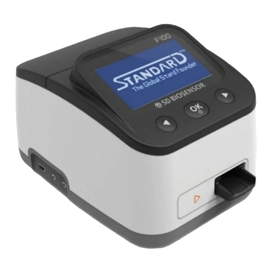
Operating conditions To ensure proper function of your STANDARD F100 analyzer, observe the following guidelines. • The STANDARD F100 analyzer is only for interior use. • Operate the analyzer only within the acceptable environmental conditions; temperature: 0-50°C, humidity: 10-93%. • In order to perform a measurement, place the analyzer on a level surface or hold it in your hand. - Page 11 Overview of F100 Analyzer C.LCD D.Right Button B.Center (Enter) Button A.Left Button E.Strip Slot G.Printer Port, Additional Port F.PC Communication Port H.Battery Compartment Lid I.DC Jack Port A. Left Button : Use for moving cursor or exit test mode B. Center (Enter) Button : Use for power on/off or menu selection C.
-
Page 12: Standard F100 Display
(If you have STANDARD thermal printer) H. Battery Compartment Lid : Provide access to the battery compartment (4 AA 1.5V alkaline batteries) I. DC Jack Port : Connect power supply adapter 5V/2A STANDARD F100 Display Battery level Beep ON AC adapter in... -
Page 13: Power Supply
Power Supply 5V/2A AC/DC power adapter or 4 AA alkaline batteries can be used. When using batteries, to save power, the analyzer turns itself off after 1 minutes unless a button is pressed or a new test strip is inserted. When the analyzer turns itself off, all test results obtained so far remain in the memory. -
Page 14: Chapter 03. Setting And Performing
STEP 1-1. Insert batteries The requested batteries are 1.5V AA-sized alkaline manganese batteries. To avoid the risk of trouble, do not use rechargeable batteries in the STANDARD F100 analyzer. 1. Open the battery lid by slightly pressing the cover towards the center of the analyzer. -
Page 15: Set The Analyzer
STEP 1-2. Connect AC/DC adapter jack 1. SD BIOSENSOR doesn’t provide adopter. (You can use AC/DC adapter jack that is 4 mm external-diameter and 1.7 mm internal-diameter, and output is 5V/2A.) 2. Connect AC/DC adapter jack to the DC jack port at the back of analyzer. - Page 16 Entering set mode Standard Read Setting Calibration Review Test Only Date Set Time Set Unit Set Beep Next Page Back Language Delete Print Set F/W Info Back Memory F/W Version F/W Update Back 1. If you want to enter the setting mode, press the ◄ or ► button to move the cursor.
- Page 17 Main Menu Date Setting Menu Language Setting Menu...
- Page 18 Date Set At 1 stage, set the date. Standard Read Setting Calibration Review Test Only Date Set Time Set Unit Set Beep Next Page Back Language Delete Print Set F/W Info Back Memory F/W Version F/W Update Back The first menu is ‘Date Set’. In the Setting Menu, select the ‘Date Set’ to change the present date.
- Page 19 Time Set At 2 stage, set the time. Standard Read Setting Calibration Review Test Only Date Set Time Set Unit Set Beep Next Page Back Language Delete Print Set F/W Info Back Memory F/W Version F/W Update Back The second menu is ‘Time Set’. You can set up the hour, minute, second, and 12h or 24h time format.
- Page 20 Back The third menu is ‘Unit Set’. Unit set is only for quantitative analysis STANDARD F100 analyzer applies corresponding unit. When you carry out the quantitative analysis of sample, STANDARD F100 analyzer applies corresponding unit. The parameters can be increased by update of analyzer software.
- Page 21 Beep Set At 4 stage, set the beep – ON / OFF. Standard Read Setting Calibration Review Test Only Date Set Time Set Unit Set Beep Next Page Back Language Delete Print Set F/W Info Back Memory F/W Version F/W Update Back The fourth menu is ‘Beep’.
- Page 22 Language Set At 5 stage, set the language. Standard Read Setting Calibration Review Test Only Date Set Time Set Unit Set Beep Next Page Back Language Delete Print Set F/W Info Back Memory F/W Version F/W Update Back The fifth menu is ‘Language Set’. From the setting menu, select the ‘Language Set’.
- Page 23 Print Set At 6 stage, set the print function – ON / OFF. Standard Read Setting Calibration Review Test Only Date Set Time Set Unit Set Beep Next Page Back Language Delete Print Set F/W Info Back Memory F/W Version F/W Update Back The sixth menu is ‘Print Set’.
- Page 24 Delete Memory In 7 stage, set the delete memory mode. Standard Read Setting Calibration Review Test Only Date Set Time Set Unit Set Beep Next Page Back Language Delete Print Set F/W Info Back Memory F/W Version F/W Update Back The seventh menu is ‘Delete Memory’.
- Page 25 F/W Info At 8 stage, check the F/W information. Standard Read Setting Calibration Review Test Only Date Set Time Set Unit Set Beep Next Page Back Language Delete Print Set F/W Info Back Memory F/W Version F/W Update Back The eighth menu is ‘F/W Info’. You can verify the F/W information such as F/W version and F/W update.
- Page 26 FIRMWARE UPDATE PROCEDURE PROCEDURE FOR THE COMPUTER PROCEDURE FOR THE F100 0. Be sure connect the power cable to STANDARD F100 analyzer before updating the software. 1. Run firmware update program <Connect the power cable ‘F100FirmwareUpdater_VxxxRxxx. to the STANDARD F100 Analyzer>...
- Page 27 <Select the ‘Next Page’> <Select the ‘F/W Info’> <Select the ‘F/W Update’> Please connect the Mini-5pin USB cable in this step, otherwise ‘Firmware Upgrade’ button won’t be activated. <Connect ‘Mini-5pin USB cable’ to computer and F100 Analyzer>...
- Page 28 <Push the ‘Upgrade Firmware’ button once it is activated>...
- Page 29 Left button Center button Right button ◄ ► Move cursor Select Move cursor Default Setting: Current F/W Information...
-
Page 30: Performing A Measurement
Performing a Measurement Refer to the insert corresponding to specific parameters. Caution Standard Read Setting Calibration Review Test Only Select the desired test mode Standard Test mode may be most convenient for reading a single patient sample, as the user can standard test during the development period. -
Page 31: Standard Test And Read Only Modes
Press start button Press the center button( ) to start and progress after each test preparation. Patient test results When the test is complete, the results for the patient specimen test(s) will be displayed on the analyzer screen. The result can also be automatically printed through an STANDARD thermal printer if it has connected to the analyzer. - Page 32 In the Read Only mode, dispense the patient sample into the sample well. Measure the development time outside of the analyzer. This can be done on the counter or benchtop using a timer. Refer to the assay-specific package insert for the required development time.
-
Page 33: Chapter 04. Using The Analyzer Memory And Data Transfer
04. Using the Analyzer Memory and Data Transfer Displaying Stored Measured Values The STANDARD F100 analyzer saves 1000 results accompanied with measured date and time. If the new result is added into analyzer filled with memories, the analyzer deletes the old data automatically. -
Page 34: Data Transfer
Data Transfer Data can be downloaded from STANDARD F100 analyzer via USB interface. To get an information of suitable system (PC), please call your local service center. The STANDARD F100 analyzer shows you the following PC image during the data transfer. -
Page 35: Chapter 05. Calibration Set Test
05. Calibration Set Test Calibration Set Test Calibration Set Test is a required function that ensures optimal performance by checking the designated method by SD BIOSENSOR, Inc. When to use calibration set • Whenever the analyzer is powered on. • When you drop the analyzer. - Page 36 When you change the adaptor or battery, the 'Calibration?' message will be displayed on the screen. Select 'Yes' or 'No'. • If 'EEE' message displays on the screen, it means that the analyzer has a problem. Call the SD BIOSENSOR Customer Care Service Center or local distributor. Note •...
-
Page 37: Chapter 06. Shut Down, Cleaning And Maintenance
CHAPTER 06. Shut down, Cleaning and Maintenance Shut Down Turn off the analyzer by pressing the center button. When you press the center button for 2 seconds, 'Power OFF?' message is displayed on the screen. Press the center button to shut down the analyzer. Shutdown is complete when the screen goes dark. -
Page 38: Chapter 07. Screen Messages And Troubleshooting
CHAPTER 07. Screen Messages and Troubleshooting Warning Messages Indication Warning description Warning: Low Battery At this time, battery is getting low but you can still perform about 10 tests. Solution Replace the battery as soon as possible. Warning: Replace Battery Battery power is low. -
Page 39: Error Messages
Error Messages In certain circumstances error messages may appear on your display. Generally, you should first try the solutions suggested for the respective error. If the problem persists, please contact your local distributor and service center. Indication Warning description E-1 - Error: Strip Error The test strip has been used or is contaminated. - Page 40 If the error continues, turn off an analyzer. Then turn on the analyzer again. If there is still error massage, please contact SD BIOSENSOR, Inc. E-6 - Error: Extremely low Total hemoglobin means that the measured total hemoglobin is under 7g/dl.
-
Page 41: Annex
Professionals Protection against Infections There is a potential risk of infection. Medical staff using the STANDARD F100 analyzer to perform measurements for more than one patient must be aware that any object coming into contact with human sample is a potential source of infection. - Page 42 MT Promedt Consultign GmbH Altenhofstrasse 80 D-66386 St. Ingbert Germany Phone : +49 6894 581020, Fax : +49 6894 581021 Manufactured by SD Biosensor, Inc. Head Office C-4th&5th, 16, Deogyeong-daero, 1556beon-gil, Yeongtong-gu, Suwon-si, Gyeonggi-do, 16690, REPUBLIC OF KOREA Manufacturing Site...
Need help?
Do you have a question about the F100 and is the answer not in the manual?
Questions and answers