Table of Contents
Advertisement
Quick Links
Advertisement
Table of Contents

Related Manuals for SD Biosensor STANDARD F2400


Summary of Contents for SD Biosensor STANDARD F2400
- Page 1 User Manual for STANDARD F2400 Analyzer Medical Device Manufacturer : Manufacturing Site: 74, Osongsaengmyeong 4-ro, Osong-eup, Heungdeok-gu, Cheongju-si, Chungcheongbuk-do +82-31-300-0400 +82-31-300-0499 sales@sdbiosensor.com www.sdbiosensor.com...
- Page 3 Please read the instructions carefully which are included in each test device package before using the Analyzer. If you have any questions about the analyzer, please contact your local distributor. You can also visit www.sdbiosensor.com for product demonstrations. Again, thank you for purchasing the STANDARD F2400 Analyzer.
- Page 4 Product Overview ......................12 Precautions before perform a test ................13 Specifications ........................15 Appearance of STANDARD F2400 Analyzer ............16 Accessories of the STANDARD F2400 Analyzer............. 18 Chapter 03. Log On and Setting ..................19 Operation of Analyzer ....................19 Chapter 04.
- Page 5 Chapter 07. Cleaning & Maintenance ................52 Cleaning of Analyzer ....................52 Maintenance & Transportation .................. 52 Chapter 08. Messages & Troubleshooting ..............53 Warning Messages......................53 Error Messages ....................... 54 ANNEX 01. Information for Professional Medical Personnel........57 Protection from Infection ................... 57 Electromagnetic compatibility ..................
- Page 6 Chapter 01. General Information Log On Main Menu Structure Work Place Calibration Test Result Calibration Run QC Test Status Review Calibration Review Revi Prepare Start (Input QC with Operator ID) Device External Control solution Insert Insert Device Device CAL-1 Input Insert Control ID Device...
- Page 7 Utility Monthly Result System Maintenance Statistics Operator Network review Review Date Network /Time ernal Edit HIS/LIS Print vice Delete Language vice cking Update ntrol mation Brightness /Volume mple mple cking nting...
- Page 8 Symbols and Abbreviation The symbols and abbreviation presented below are indicated on the User Manual, labels and external package. Symbols Symbols Description Manufacturer In vitro diagnostic medical device Intended to use outside the body Consult instructions for use Reference Number Date of Manufacture To indicate the date of manufacture Serial Number...
- Page 9 Abbreviations Abbreviation Description Comm Communication Laboratory Information System Hospital Information System Graphic User Interface Software Firmware...
- Page 10 · There is a risk of electric shock if Analyzer is not grounded. Use the power cable provided by the SD Biosensor. It is recommended to use a power cable of 250V ~, 10A, 0.75mm2 (18 AWG).
- Page 11 To reduce the risk of biological hazards · Discard the used specimens in accordance with federal, state Biohazard! and local requirements. · Treat specimens as potentially biohazardous material. · If you have no experience with collection and handling of specimens, appropriate education or guidance should be received.
- Page 12 Chapter 2. Overview Intended Use STANDARD F2400 Analyzer is an in vitro diagnostic medical device that measures quantitative or qualitative biomarkers of body fluids such as blood, urine, nasal discharge, etc., in a laboratory or POCT environment. The analyzer is indicated for monitoring and diagnosing from the body fluid parameter in clinical settings by healthcare professionals.
- Page 13 Specimens The STANDARD F2400 Analyzer should be only used the specific test devices for the analyzer. Because specimens are quite different for each parameter, follow the instructions from the each test device instructions.
- Page 14 Operating Conditions To operate the STANDARD F2400 Analyzer correctly, the following guidelines should be observed : · The operating conditions of the Analyzer are: 0℃-50℃ / 32℉-122℉, 10%- 93% RH. · The operating temperature suitable for analyses differs in each test. For each test, refer to the instruction manual of the test device that you will use for analyses.
- Page 15 Specification AC 100~240V, 50/60Hz Input Voltage 10.1” Color TFT LCD (1024 X 600) Display Graphic User Interface Display Control Up to 84W Power Consumption 5,000 (Run Test) Number of Memories Including RTC Backup Battery Real Time Clock HL7 PCD – 01 Profile Support LIS / HIS 510 X 566 X 297 mm Dimension...
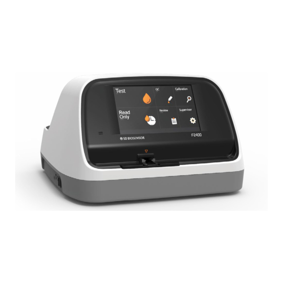
- Page 16 Appearance of STANDARD F2400 Analyzer...
- Page 17 Used to connect the Analyzer to keyboard, barcode scanner and USB memory USB should be formatted as FAT32, so that the USB can be recognized by STANDARD F2400 Analyzer. Note K. Additional device connection part Only use for connecting specific device that is produced by SD Biosensor, Inc...
- Page 18 Accessories of the STANDARD F2400 Analyzer STANDARD F Calibration Set Accessories AC Power cable STANDARD F Test Device (Example : HbA1c, Influenza A/B) Barcode scanner Optional Printer paper...
- Page 19 Chapter 3. Log On and Setting Operation of Analyzer Step 1. Connecting the power cable 1-1. Place the Analyzer in a proper environment where it can be plugged into outlet and barcode scanner (optional) can be positioned together. 1-2. Connect the power cable to the power connector on the back of the Analyzer and to the outlet.
- Page 20 Step 2: Setting Mode 1. Touch ‘Utility’ on the main menu screen to enter the setting mode. 2. Utility menu consists of submenus: System, Maintenance, Statistics, Operator, and Network. System submenu can be used to set the Date/Time, Language, Print, Brightness/Volume and proceed with the update. ①...
- Page 21 ) to select the desired language from the drop- down list. 4 ) Update ① S/W Update Items needed for S/W update · STANDARD F2400 Analyzer · Software update file · USB(Not provided) · Personal computer(Not provided) How to update the software a.
- Page 22 Make sure that the latest S/W version is displayed in the lower left corner of the screen. ② F/W Update Items needed for F/W update · STANDARD F2400 Analyzer · Firmware update file · Mini-5pin USB cable · Personal computer(Not provided) How to update the F/W a.
- Page 23 c. Press “OK”. d. Run the PC program. e. When the Update Firmware button is enabled, click the button. f. Click“Update Firmware” on the PC and then press “OK” on the Analyzer.
- Page 24 g. When the update is completed on the PC, press the OK button h. Press “OK”on the screen to complete FW Update. 5) Brightness/Volume setting ① Use buttons or the slider to adjust screen brightness. ② Use buttons or the slider to adjust the volume.
- Page 25 Maintenance Menu 1) On the Maintenance tab, you can check the maintenance status and log of each item. ① ② ③ ④ ⑤ ⑥ ① Maintenance Area: Tested items are displayed. ② Status Area: QC scheduled date for tested item is displayed. The QC period can be set from due date in Area ③...
- Page 26 Statistics Menu 1) On the Statistics tab, you can check the number of tests, calibration, and QC tests for each item. ④ ⑤ ② ① ③ ① The number of times that each test has been performed is displayed. ② The type and number of times of errors that occurred are displayed. ③...
- Page 27 Operator Menu 1) An Operator item can be registered, edited, and deleted. · Password in Operator is the same as the password used for log-on. · To add an Operator ID, press “Add” .
- Page 28 · To modify the Operator ID, select the ID,, press “Edit”, type ID you wish to modify, and then press “OK”...
- Page 29 · To delete the Operator ID, select the ID, select the ID, press “Delete”, then press “ OK” Network Menu 1) On the Network tab, you can set the HIS/LIS and Analyzer network. For the methods of setting, consult with your interface specialist.
- Page 30 Chapter 4. Work Place Performing a Test & Reviewing data Before proceeding a test, check the following : · Is the power cable connected to the Analyzer? · Are the date and time settings of the Analyzer correct? · Are all other settings correct? 1.
- Page 31 1) Run test Menu “Run test” is a mode for testing the samples from patients. ① After entering patient information in “Patient ID”, press to move to the next step. Patient ID can be entered by using the touch keyboard. You can also enter Patient ID by using a barcode scanner or by an external keyboard connected by USB.
- Page 32 ③ Analyzer checks the conditions of the inserted test device. If the test device has already been used, E-1 error pops up. ④ After confirming that the test device can be used with STANDARD F2400, the samples should be prepared according to the instruction for each test and applied to the sample well of the test device.
- Page 33 ⑤ Analyzer checks the applied sample’s conditions and flow. ⑥ When the sample checking is completed, the test deviceis mounted inside the Analyzer. ⑦ When the mounting is completed, you can start a new test procedure.
- Page 34 2) Test Status Menu “Test Status” menu shows the progress of test in the Analyzer. Blue section is shown in the following cases: · If the test is completed correctly. · If the result of qualitative test is Negative · If the result of quantitative test is within the normal range.
- Page 35 ① If you select a completed item, you can check details of the test(test result, name label, procedural control, test date and time, Operator ID, Patient ID, manufacturing date of the test deivce, software version). In this window, you can print the test result by pressing on “Print”. Press “OK”...
- Page 36 ① Select from the drop-down list on the right. And select a test from list shown in [Area A]. All of the test results belonging to the selected Patient ID will be shown in [Area B]. If you select a particular test from the drop-down list, you can see the tests in order from the most recent ones.
- Page 37 · Test details window for quantitative test – Example) HbA1c For quantitative test, you can change the measurement unit by pressing the item under “Units” in the list on the right side[Area B]. (Available only when there are 2 or more types of measurement units.)
- Page 38 Chapter 05. Calibration Calibration Set Test Calibration Set Test is an essential function that ensures optimal performance of the Analyzer by checking the methods specified in the Manual. Time for use of Calibration Set · Whenever the Analyzer is turned on ·...
- Page 39 ① Insert the Cal-1 Device into the test slot of the Analyzer. ② After checking the Cal-1 Device, insert the Cal-2 Device into the test slot of the Analyzer. ③ After checking the Cal-2 Device, insert the Cal-3 Device into the test slot of the Analyzer.
- Page 40 ④ After inserting all the calibration devices, the analyzers performs the calibration analysis. ⑤ When the analysis is completed, you can check the result screen. · Calibration check- OK screen · Calibration check- FAIL screen...
- Page 41 2. Calibration Review Menu The result of calibration can be checked in “Calibration Review”. ① You can check the details by selecting the Result from the list. · Calibration Review - OK screen · Calibration Review - FAIL Screen...
- Page 42 ② Select a list and press “Delete Record”( ) to clear the selected items. Press the “Delete All”( ) to clear all results.
- Page 43 Chapter 6. Quality Control Quality Control Test To verify whether the Analyzer’s system is functioning properly and whether the test procedure is correct, perform QC with one or more levels of quality control materials. Time for use of Calibration Set ·...
- Page 44 1) QC with Control solution ① Select “QC with Control solution” and the next screen will be shown. ② Enter the information of quality control material (barcode number) and press OK to proceed to the next step. ③ Insert a test device that matches the quality control material information entered on the Insert Device screen.
- Page 45 ④ The Analyzer checks the conditions of inserted test device. If the test device has already been used, an E-1 error pops up. ⑤ When the verification of the test device is completed, apply the control to the sample well of the test device and immediately press “QC Start”.
- Page 46 ⑦ After the check is completed, the test device is mounted inside the Analyzer. ⑧ Once the mounting is complete, you can start a test procedure. 2) External QC ① Press “External QC” to move to the next screen. ② Insert the test device to test on the Insert Device screen.
- Page 47 ③ Analyzer checks the conditions of inserted test device. If the test device has already been used, an E-1 error pops up. ④ When the verification is completed, a screen for setting the range of quality control material appears. ⑤ Set the information of the quality control material to be used and press “OK”...
- Page 48 · Example of Quantitative test ⑥ After applying the prepared quality control material, press “QC Start” immediately. ⑦ The F2400 Analyzer checks the conditions and flow of applied sample.
- Page 49 ⑧ Once the verification is completed, the test device is mounted inside the Analyzer. 3) QC Result review Menu ① You can check the result of QC in “QC Result review”. ⓒ ⓔ ⓓ ⓐ ⓑ a. The number of times that QC was performed, average, standard deviation, coefficient of variation, and the result of ±...
- Page 50 d. If you select the test you want to view from the drop-down list, you can check the QC result of selected test. Example) The results obtained when result retrieval period is set to 2018.1.17-2018.4.19 and then HbA1c is selected from the drop- down list Example) The results obtained when result retrieval period is set to 2018.1.17-2018.4.19 and then Strep A is selected from the drop-...
- Page 51 ② If you select from the list, you can check the test details. 4) Monthly Review Menu In ”Monthly Review”, you can check the monthly value of quantitative test. If you select the period and press “Table”, the QC results for that period are provided in the form of a list.
- Page 52 Chapter 07. Cleaning & Maintenance Cleaning of Analyzer To prevent any malfunctioning of Analyzer, keep the test slot free from specimen moisture or dust. Clean the Analyzer with a lint-free cloth and suitable cleaning solution (example: mild soap, 70% ethanol or isopropyl alcohl). If the Analyzer is in a special environment (example: operating room), it is recommended to clean it with a mixture of 1-propanol, 2-propanol and glutaraldehyde (trade name: Bacillol plus).
- Page 53 Chapter 08. Message & Troubleshooting Warning Message Display Description of Warning Warning: No user information entered “OK” is pressed while no user information has been entered. Solution First, enter the user information and then press 'OK'. Warning: USB not connected USB is not connected to the Analyzer.
- Page 54 Warning: Incorrect IP address Incorrect IP address entered. Solution Confirm the entered IP address, and enter the correct IP address. Error Message Display Description of Warning E01: Test device error Inserted test device is contaminated or already used. Solution Discard the failed test device and retest with a new test device.
- Page 55 Communication between Analyzer and barcode or between Analyzer and printer has failed. Solution If the error persists after rebooting the Analyzer, consult the SD Biosensor. E06: Total hemoglobin amount error The total hemoglobin measured deviates from the range of 7-23 g/dL. Solution Test again with a new test device.
- Page 56 Test device applied to Analyzer is not suitable. Solution Check if the analyzer is updated with the latest version of the software. EEE: Analyzer internal error message Analyzer has an internal error. Solution If the error persists after rebooting the Analyzer, contact the SD Biosensor.
- Page 57 Medical Personnel Protection from Infection Professional medical personnel must be careful to avoid infection caused by sample, etc. while performing diagnostic test with the STANDARD F2400 Analyzer. · Wear medical gloves. · When applying sample into the sample well of test device, be careful that the sample does not contaminate any part of analyzer.
- Page 58 MEMO...
- Page 59 MEMO...
- Page 60 F2400 Manufacturer SD BIOSENSOR, Inc. Headoffice C-4th&5th, 16, Deogyeong-daero 1556beon-gil, Yeongtong-gu, Suwon-si, Gyeonggi-do, 16690, REPUBLIC OF KOREA Manufacturing site 74, Osongsaengmyeong 4-ro, Osong-eup, Heungdeok-gu, Cheongju-si, Chungcheongbuk- do, 28161, REPUBLIC OF KOREA www.sdbiosensor.com...
Need help?
Do you have a question about the STANDARD F2400 and is the answer not in the manual?
Questions and answers
Hemoglobinas bajas no leen las glicosiladas
The SD Biosensor STANDARD F2400 reads glycosylated hemoglobin (HbA1c) levels using fluorescence immunochromatography. If a patient's total hemoglobin level is below the acceptable range (less than 7 g/dL), it triggers an "E06: Total hemoglobin amount error." In this case, the test should be repeated with a new test device. If the error continues after rebooting the Analyzer, the manufacturer should be contacted.
This answer is automatically generated