Table of Contents
Advertisement
Quick Links
Advertisement
Table of Contents

Subscribe to Our Youtube Channel
Summary of Contents for Ametek Solartron Metrology Digital Mini Probe
- Page 1 DIGITAL MINI PROBE user leaflet Manual Part No. 502923 Issue 3...
-
Page 2: Table Of Contents
1.0: Index Section Title Page Section Title Page Index .......2 Specifications ..........11 Safety Summary . -
Page 3: Safety Summary
2.0: Safety Summary Terms in this Manual WARNINGS: Do not operate in an explosive atmosphere WARNING statements identify conditions To avoid explosion, do not operate this equipment or practices that could result in personal in an explosive atmosphere. This equipment is not injury or loss of life. -
Page 4: Introduction
3.0: Introduction CAUTION The Mini Probe is a compact, low profile, transducer The Mini Probe needs to be treated intended for measurements in confined spaces. carefully, as with any precision instru- The product is based on a parallel spring structure ment, to avoid damage during instal- that is significantly more robust than a single leaf lation - please see section 5 of this... -
Page 5: Components Of The Mini Probe
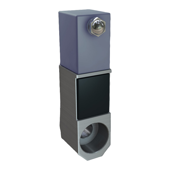
4.0: Components of the Mini Probe Adjustable Tip Location of M3 Mounting Screw Mounting Face Fluoroelastomer Boot 4.0: Components of the Mini Probe Manual Part No. 502923 Issue 3... -
Page 6: Mechanical Installation
5.0: Mechanical Installation 5.1: Positioning To ease installation, the Mini Probe head can be disconnected from the PIE. It is important that the PIE with the correct ident is used with the The Mini Probe is susceptible to some degree to the corresponding Mini Probe head. -
Page 7: Cable
5.0: Mechanical Installation 5.3: Cable To minimise transducer failure due to cable damage, cable runs should be positioned well clear of moving components and vulnerable working areas. If the PUR cable is in a flex situation, then a minimum bend radius of 150 mm should be maintained. A minimum bend radius of 1 mm is recommended for the wires coming out of the probe head. -
Page 8: Tip Adjustment
5.0: Mechanical Installation 5.4: Tip Adjustment 5.5: Tip Replacement The Mini Probe Tip height can be adjusted over a To remove tip 0.5 mm range (± 0.25 mm from the factory set position -approximately ±½ turn). 1) Firmly hold the Mini Probe frame, so that it is not stressed during the tip removal. -
Page 9: Pie / Probe Connections
6.0: PIE / Probe Connections 6.1: PIE / Probe Connections Alternatively, slide the sleeve back to expose the connector. Push the pin and socket together and To aid installation, the probe and PIE may be separated. then slide the sleeve back into position Two connection styles are used. -
Page 10: Grounding / Shielding
6.0: PIE / Probe Connections 6.1: PIE / Probe Connections (continued) 6.2: Grounding / Shielding M5 Circular Connector Pin to Pin Connection To separate the probe and PIE, hold the probe It is recommended that the spade terminal be connected connector and turn the locking ring only. -
Page 11: Specifications
7.0: Specification - See Orbit3 Catalogue For instruction on using Orbit3 see the Orbit3 System Manual supplied on the Orbit3 Support Pack for Windows CD. 7.0: Specification Manual Part No. 502923 Issue 3... -
Page 12: Outline Drawings
8.0: Outline Drawings 8.1: Mechanical Drawing - DM/05/S Standard Product - tip and specifications may vary 8.0: Outline Drawings Manual Part No. 502923 Issue 3... -
Page 13: Outline Drawings - Dm/1/S
8.0: Outline Drawings 8.2: Mechanical Drawing - DM/1/S Standard Product - tip and specifications may vary 8.0: Outline Drawings Manual Part No. 502923 Issue 3...


Need help?
Do you have a question about the Solartron Metrology Digital Mini Probe and is the answer not in the manual?
Questions and answers