Table of Contents
Advertisement
Quick Links
Advertisement
Table of Contents

Related Manuals for Ametek si 5000


Summary of Contents for Ametek si 5000
- Page 2 GENERAL TRADEMARKS AND COPYRIGHTS Information in this document is subject to change without notice. No part of this document may be reproduced or transmitted in any form or by means, electronic or mechanical, for any purpose, without the express permission of Solartron Metrology. ®...
-
Page 3: Table Of Contents
TABLE OF CONTENTS INTRODUCTION ....................................6 SCOPE ........................................6 NAVIGATE THIS DOCUMENT ................................6 SAFETY SUMMARY ..................................... 7 GLOSSARY OF TERMS AND BASIC SYSTEM INFORMATION ......................8 TERMS ASSOCIATED WITH SI5500 Read out ..........................8 ... - Page 4 Display Configuration Menu ................................22 Display Configuration Menu 2 ............................... 23 Probes Menu ....................................24 computed measurement ................................. 25 Measurement mode ..................................27 Preset/Limits Menu ..................................28 Input/Output Menu ..................................
- Page 5 SERIAL COMMANDS ..................................49 MEASUREMENT AND TIMING INFORMATION ..........................52 RETURN OF GOODS ..................................53 SI5500 User Manual 503147 Issue 5 5 of 53...
-
Page 6: Introduction
1 INTRODUCTION This manual specifically caters for the SI5500 read out with Orbit Interface. 2 SCOPE The SI5500 read out can interface up to 31 Orbit Sensors and communicates through Orbit Serial Protocol (via Orbit Interface). It can interface with Orbit Digital Probes, Linear Encoders and Encoder Input Modules. The readings from the sensors are displayed on the front panel LCD display. -
Page 7: Safety Summary
4 SAFETY SUMMARY WARNING Warnings and Cautions statements identify conditions or practices that could result in personal injury or loss of life. Warning: Do not operate in an explosive atmosphere. CAUTION statements identify conditions or Warning: this equipment is not intended for safety critical applications practices that could result in damage to the equipment or other property Warning:... -
Page 8: Glossary Of Terms And Basic System Information
5 GLOSSARY OF TERMS AND BASIC SYSTEM INFORMATION 5.1 TERMS ASSOCIATED WITH SI5500 READ OUT Display The Liquid Crystal Display mounted on the front panel of the read out providing displayed information Keypad The 9-button keypad (3x3) mounted on the front panel of the read out allowing functional and menu navigation Discrete Inputs Digital lines into the read out which allows remote control of certain parameters/functionalities Discrete Outputs... - Page 9 Measurement Mode This information represents the current measurement mode of the channel. It can take the values of ABS(Absolute), TARE(ZERO), PRE(Preset) ABS(Absolute) – In this mode the displayed reading is same as the current absolute reading. TARE(ZERO) – In this mode the displayed reading is referenced to a “Zero” value. PRE(Preset) –...
-
Page 10: Electrical Installation
6 ELECTRICAL INSTALLATION This section describes how to connect the unit. I/O Connector RS232 COMM Connector Refer to Discrete Lines Refer to RS232 section section for pin details and for pin details input/output schematic details 24V DC Input Connect the DC power adapter supplied as an accessory along with the read out. -
Page 11: Display And Keypad
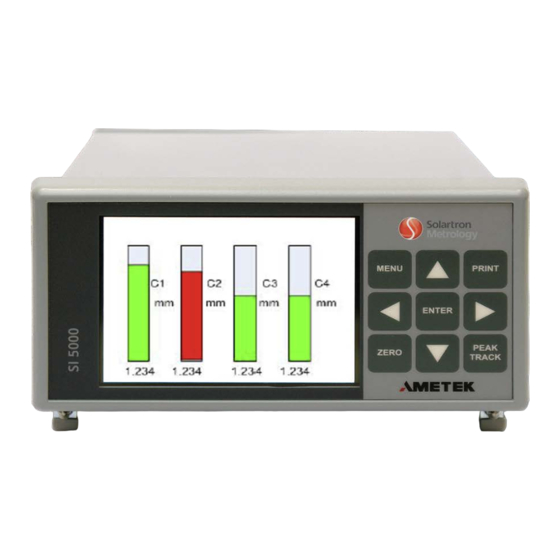
7 DISPLAY AND KEYPAD SI5500 operates in four modes of display namely: OPERATE SCREEN, MENU SCREEN, GAUGING SCREEN and AUTOSENSE SCREEN 7.1 OPERATE SCREEN The calculated readings are displayed in this mode. The operate screen can be of Single Channel Bar Display, Dual Channel Bar Display, 4-Channel Bar Display, 8-Channel Bar Display, 16-Channel Bar Display, 8-Channel Text Display, 16-Channel Text Display. - Page 12 4-Channel Display Configuration This mode displays 4 consecutive channel readings in bar panel mode. The blue cursor on top of the bar indicates the current selected channel. NOTE that the resolution of max/min range values is limited to 3 decimal point resolution due to constraint in the available display area. User can switch over to Single Channel Display Configuration for getting complete information about the measurement channel.
- Page 13 P-_AB – Operation mode is PEAK-, Measurement mode is ABS P-_ZE – Operation mode is PEAK-, Measurement mode is ZERO P-_PR – Operation mode is PEAK-, Measurement mode is PRESET 16-Channel Bar Display Configuration This mode displays the 16 consecutive channel readings in bar mode. The blue cursor on top of the bar indicates the current selected channel. NOTE that in this mode the readings and no other information related to the measurement channel is displayed.
- Page 14 8-Channel Text mode configuration This mode displays the 8 consecutive channel readings in text mode. The blue cursor on left of the channel reading indicates the selected channel. User can switch to Single Channel Configuration for getting the complete information about that channel. SI5500 User Manual 503147 Issue 5 14 of 53...
- Page 15 16-Channel Text Mode Configuration This mode displays the 16 consecutive channel readings in text mode. The blue cursor on left of the channel reading indicates the selected channel. User can switch to Single Channel Configuration for getting the complete information about that channel. SI5500 User Manual 503147 Issue 5 15 of 53...
- Page 16 Single channel configuration This mode displays all the properties of the measurement channel. User can switch to this mode to get all the required information of the selected channel. Channel Number varies from: Configured Expression/Formula C1 to C31 Measurement Mode: Can take values TRACK, PEAK+, PEAK- Operation Mode:...
-
Page 17: Switching To The Single Channel Configuration For The Selected Channel
7.2 SWITCHING TO THE SINGLE CHANNEL CONFIGURATION FOR THE SELECTED CHANNEL To switch to single channel mode from any multi-channel configuration below steps has to be followed: Use and arrow keys in the multi-channel configuration to select the required channel. ... -
Page 18: Gauging Mode Screen
7.4 GAUGING MODE SCREEN This screen displays the result when Gauging mode is enabled. Gauging mode is used to check if all the selected number of channels is within limits. The count of channels to be used for gauging mode can be configured through “Advanced Measurement Mode” menu screen. If all the channels selected for scanning are within limits, then “PASS”... -
Page 19: Autosense Mode Screen
7.5 AUTOSENSE MODE SCREEN This screen displays the result when Autosense mode is enabled. Autosense mode is used to automatically select the channel which is within limits. The count of channels to be used for scanning can be set through Autosense Mode menu screen. When a channel is within limits, it is displayed in Single Channel Configuration mode. -
Page 20: Menu Screen
8 MENU SCREEN The MENU screens are used to set up/configure the read out. Menu Screen can be activate through MENU key button on the keypad. The current screen is stored and displayed back when MENU Screen mode is exit. In MENU Screen mode the keypad functionality is as per the table below: DESCRIPTION MENU... -
Page 21: Setup Menu
ENTER - ENTER key will stop edit mode. The final number (- 020.00000) will be saved and used further. 8.1 SETUP MENU The main SetUp Menu has two pages (Page1 and Page2). SetUp Menu Page 1 SetUp Menu Page 2 Display Configuration Input/Output ... -
Page 22: Display Configuration Menu
8.2 DISPLAY CONFIGURATION MENU Display Configuration Menu OPTIONS Display Config 1Ch, 2Ch, 4Ch, 8Ch Bar, 8Ch Txt, 16 Ch Bar, 16Ch Txt 1, 2, 3, 4, 5 Places after DP +000.00000 Bar Offset OFF, ON Bar AutoRange ZERO/PRESET all OFF, ON 1, 2, 3, 4, 5 Last Digit Step Next Menu... -
Page 23: Display Configuration Menu 2
8.3 DISPLAY CONFIGURATION MENU 2 Display Configuration Menu 2 OPTIONS Displacement: mm, inch, mils degC, degF Temperature: Back Exit Menu This menu controls the units of measure scaling for the types of input shown (eg converting mm to inches). The settings in this menu affect available units thoughout the system (see section 8.5 for more details). SI5500 User Manual 503147 Issue 5 23 of 53... -
Page 24: Probes Menu
8.4 PROBES MENU Sensor number: Varies from ‘A’ to ‘Z’ and from ‘a’ to ‘e’. Probes Menu – Sensor A OPTIONS Probe Type Orbit Direction Retract+, Extend- These fields are not user editable- Will be filled Range +123.00000 automatically according to the sensor Notified. NOTE: The Pulses/Rev option is valid only for EIM Probe ID ABCDEFGHIJ... -
Page 25: Computed Measurement
8.5 COMPUTED MEASUREMENT Computed Measurement Menu OPTIONS Channel Nr C1, C2, C3, ……., C31 User defined formula corresponding to the selected Channel Nr. Expression MAXA mm, inch, mils, deg, V, mV, A, mA, degC, Units This full list of units is limited by the degF, bar, hPa, MPa, kPA, mg, Kg, rpm selections in the Display Configuration Uni-/Bi-Polar... - Page 26 Opr, Opd, Num, Math options provides a pop-up window containing various mathematical operators, trigonometric functions and sensor numbers (used as operands for mathematical or trigonometric functions) defined in the table below. Opr - +, -, *, /, (, ), , Exit Opd –...
-
Page 27: Measurement Mode
8.6 MEASUREMENT MODE Measurement Mode Menu OPTIONS Channel Nr C1, C2, C3, ……., C31 Measure Mode TRACK, PEAK+, PEAK- These options are applicable only for Reset Mode Manual, Automatic PEAK+ and PEAK- measure mode options. It will be displayed only if the corresponding Trigger Time(ms) 12345 channel is in PEAK+ or PEAK-... -
Page 28: Preset/Limits Menu
8.7 PRESET/LIMITS MENU Preset/Limits Menu OPTIONS Channel Nr C1, C2, C3, ……., C31 Preset +000.00000 Upper Limit +003.00000 Lower Limit -003.00000 Exit Menu SI5500 User Manual 503147 Issue 5 28 of 53... -
Page 29: Input/Output Menu
8.8 INPUT/OUTPUT MENU Input/Output – Page 1 Logic Outputs Active LOW, Active HIGH <C1, C2, C3, …., C31> <OK, Under, Over, None> Out1 <ChNr> <Func> Out2 <ChNr> <Func> <C1, C2, C3, …., C31> <OK, Under, Over, None> Out3 <ChNr> <Func> <C1, C2, C3, …., C31>... -
Page 30: Pin Details Of Discrete Outputs
SI5500 supports 6 discrete inputs and 6 discrete outputs. The discrete outputs can be mapped to any channel number through menu screen shown above. “OK” Control Function: Output is set when the reading for the associated channel is within limits. “Over”... - Page 31 PRESET PRESET Edge Input type. When this input is set active, PRESET Edge Input type. When this input is set active, PRESET operation will be performed on the current selected operation will be performed on the current selected channel or all channels according to the ZERO/PRESET channel or all channels according to the ZERO/PRESET all configuration all configuration...
-
Page 32: Print Options
External Supply 10V to 24V DC PINS – 17,5,18,6,19,7 Load (up to 500mA) PINS – 1,14,2,15,3,16 PIN - 4 PIN 20 Discrete Inputs Schematic Discrete Outputs Schematic 8.9 PRINT OPTIONS SI5500 User Manual 503147 Issue 5 32 of 53... - Page 33 PRINT OPTIONS Menu OPTIONS KeyPress Single, Continuous Discrete I/P Single, Continuous Print Mode This Reading, Reading+Step, All Readings Exit Menu Single PRINT will send the data onto RS232 only once. Continuous PRINT will send data onto RS232 continuously. The PRINT key or the discrete input functionality depends on the current mode in which SI5500 is operating. Below table summarizes the same: Print Mode OPERATE SCREEN GAUGING MODE...
- Page 34 channels display is changed to STATIC mode and the current displayed channel reading is printed. Each PRINT will advance to the next channel and prints the reading. After the last channel selected for scan is printed, the display reverts back to the first channel.
-
Page 35: Print Format
8.9.1 PRINT FORMAT Current Readings: In any mode the current readings of the measurement channels are printed in the format below: Reading Right aligned with DP set throgh Units "Places after DP" setting in "Display Configuration" menu > < Limits Description >... - Page 36 Current, Max, Min Readings: In any mode Current, Max, Min readings of the measurement channels are printed in the format below: Reading Max. Reading Max. Reading Right aligned with DP set Right aligned with DP set Right aligned with DP set throgh "Places after DP"...
- Page 37 PEAK Mode Print Format: The readings in the PEAK mode are printed in the below format: PEAK Reading Eg: PEAK readings values +7.4982, +10.6290 and +9.1863 are displayed as below The calculated result values are printed in the below format: SI5500 User Manual 503147 Issue 5 37 of 53...
-
Page 38: Serial Port Menu
Result value Eg: Max=+7.4982, Min=+7.3716, Range=+0.1266 and Average=+7.3915 8.10 SERIAL PORT MENU Serial Port Menu OPTIONS Baud Rate 1200, 2400, 4800, 9600, 19200, 38400, 57600, 115200, 187500 No of Data Bits 7, 8, 9 No of Stop Bits 0.5, 1, 1.5, 2 Parity Odd, Even, None Exit Menu... -
Page 39: Advanced Measurement Mode Menu
PIN Description Not Used RS232 Tx RS232 Rx Not Used RS232 GND Not Used Not Used Not Used Not Used 8.11 ADVANCED MEASUREMENT MODE MENU SI5500 User Manual 503147 Issue 5 39 of 53... - Page 40 Advanced Measurement OPTIONS Mode Menu Advanced Mode None, Gauging, Autosense, PEAK mode Menu screen when “Advanced Mode” is set to None. The other menu options get enabled Exit Menu according to the advanced mode selected. Gauging mode selected Autosense mode selected Advanced Measurement Mode Menu Advanced Measurement Mode Menu OPTIONS...
-
Page 41: Peak Mode
8.11.1 PEAK MODE Advanced Measurement Mode Menu OPTIONS Advanced Mode None, Gauging, Autosense, PEAK mode Channel Nr 1 to 31 2 to 99 No. of Readings Exit Menu PEAK mode is designed to take up to 99 numbers of PEAK readings as input, analyze the same and display the calculated result values. When PEAK mode is selected, the unit enters into “acquisition phase”... -
Page 42: Utilities Menu
8.12 UTILITIES MENU Utilities Menu This option reset all the configuration Restore Factory Settings data to default values. All the probes notified information are lost and has to be Password Settings notified once again. Logging Settings A pop-up message indicating “FACTORY SETTINGS RESTORED. -
Page 43: Logging Settings
8.12.1 LOGGING SETTINGS Logging Settings – Page 1 OPTIONS Mode Standard, Start on I/P, Trig. on I/P Interval(ms) 0001000 Duration(ms) 0040000 Channel Count 1 to 31 Back Next Menu Opens a pop-up window OPTIONS to choose the Log Page Logging Settings – Page 2 Log Page Current, Page1, Page2, Page3, Start Logging... - Page 44 FLASH through selecting one of Page1 to Page8. Each “Page” is of 512KB in size and can hold up to 4K readings from each measurement channel when all the 31 channels are selected for logging. The number of readings can increase if less than 31 channels are selected for logging. The “Start Logging”...
-
Page 45: Screen Settings
Mean Ch: Mean of the readings StdDev Ch: Standard Deviation of the readings 8.12.2 SCREEN SETTINGS Screen Settings OPTIONS Contrast 0, 5, 10, 15, 20, 25, 30, 35, 40, 45, 50, 55, 60, 65, 70, 75, 80, 85, 90, 95, Exit Menu LCD screen contrast setting can be adjusted with the provided contrast levels options. -
Page 46: Setting Up Probes
9 SETTING UP PROBES After making the connections as explained in ELECTRICAL INSTALLATION section, go to SetUp Menu Page-1 through MENU Key and then select “Probes” option to enter the Probes Menu. In “Probes” menu, select the direction as Retract+ for Spring-Push type probe and as Extend- for Pneumatic type probe and select NOTIFY. The NOTIFY screen will be displayed with an on-screen tip. -
Page 47: Setup Steps Before Starting Measurement
Probes Menu – Sensor A Probes Menu – Sensor A SetUp Menu Page 1 Probe Type Orbit Probe Type Orbit Display Configuration Direction Retract+ Direction Retract+ Probes Range Range Computed Measurement ENTER Probe ID Probe ID Measurement Mode Preset/Limits Move the Probe Tip or Select Notify... - Page 48 Perform a ZERO operation - This operation will set the current reading of all the channels to Zero. Press ZERO key to perform this operation. Alternatively, the operation can also be performed through a discrete input. Refer to Input/Output Menu section for configuration and pin details of discrete inputs.
- Page 49 10 SERIAL COMMANDS SI5500 supports two serial PRINT commands and basic zeroing/presetting commands named below: SI5500 Zero Preset and Absolute Commands: These commands are used to Zero the readings, apply a preset, or return a measurement to absolute mode Command Bytes –...
- Page 50 Reading Lower Limit Upper Limit User defined Right aligned with DP set Right aligned with DP set Right aligned with DP set formula throgh "Places after DP" Units throgh "Places after DP" throgh "Places after DP" Mode (Upto 100 setting in "Display setting in "Display setting in "Display chars)
- Page 51 Reading Right aligned with DP set throgh Units "Places after DP" setting in "Display Configuration" menu Eg: For channel C1 with reading as +1.34815 with units as inch, within limits SI5500 User Manual 503147 Issue 5 51 of 53...
- Page 52 11 MEASUREMENT AND TIMING INFORMATION Parameter Update Rate/Value Remarks Data Reading rate from Every 20ms This also depends on how many channels use MAX or MIN or the Orbit Sensors DIFF operators in their formula. If we have more channels using these operators, then the data read rate can become slower (can become greater than 20ms).
- Page 53 12 RETURN OF GOODS Devices returned for service/repair/calibration should Please note: be shipped prepaid to your distributor or, if purchased A standard assessment charge is applicable on all non-warranty directly from Solartron Metrology, to the relevant Sales devices returned for repair. Office.
Need help?
Do you have a question about the si 5000 and is the answer not in the manual?
Questions and answers