Advertisement
Quick Links
Advertisement

Related Manuals for Ultimaker Heated Bed Upgrade Kit


Summary of Contents for Ultimaker Heated Bed Upgrade Kit
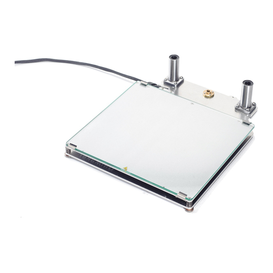
- Page 1 Original Heated Bed Assembly manual English V1.0...
-
Page 3: Table Of Contents
Table of Contents Introduction & Specification p. 4 Preparing the frame. p. 5 Mounting the electronics. p. 11 Assembling the Z-stage. p. 15 Installing the Z-stage & electronics. p. 24 Updating the Firmware and Calibration p. 33... -
Page 4: Introduction & Specification
Introduction & Specification Dear customer, Thank you for purchasing the Heated Bed Upgrade Kit for your Ultimaker Original! This assembly manual will guide you through the build process step by step. Besides this assembly manual there’s also a brand new user manual available online: www.ultimaker.com/pages/support/manuals... -
Page 5: Preparing The Frame
Preparing the frame. Part Amount Drill bit 14mm Drill bit 3,2mm Handdrill 7 Warning: When installing electronics or prefor - Scissors ming any other maintenance on the machine, make sure (Blue) Tape you are staticly discharged and ALWAYS DISCONNECT Hex Key Screwdriver 2 THE POWER SUPPLY from the machine. - Page 6 Use the Hex Key Wrench 1.5 to Unscrew the Top caps (3B) undo the top two screws in the so you can remove the guiding Z-coupling. rods. Remember to save all the nuts and bolts...
- Page 7 Remove the guiding rods Lift the bed upwards and tilt from the frame it to remove it from the frame.
- Page 8 Remove these 4 screws Turn the machine on its side from the Z-motor and save the remove the Z-motor screws, you will re-use them to install the new motor...
- Page 9 Line up the template with Take the two templates and the tape. You can use any tape the back left corner of the you want, just make sure it frame and secure it with tape. sticks to the wood. Take the handdrill and the 14mm drill bit, and drill out the hole.
- Page 10 Cut out the Heated Bed Line up the hole in the PCB Template. template with the hole you just drilled. Tape the template in place. Take the drill and the 3.2mm bit, and drill through the 4 black circles in the tem - plate.
-
Page 11: Mounting The Electronics
Mounting the electronics Note: Make sure you have al the parts before you start with the next step. Part Amount Hexagon Spacer M3X25mm Screw Black 10MM spacer M3X10mm Screw Heated Bed PCB Heated Bed PCB Cover Heated bed upgrade power cable Heated bed upgrade temperature cable Heated bed upgrade switch cable 7 Warning:... - Page 12 Remove the cover from the electronics and disconnect the fan, this makes the next steps easier and Now put the pcb in place Put the 4 M3x25mm screws and secure it with the 4 white through the holes you just Hexagon Spacers and screw drilled and place the 4 10mm the 3 M3x 10mm scews in the...
- Page 13 Take the 3 Cables that On the Mainboard screw came with the Heated Bed Up - open the screwterminal mar - grade kit and take the one with ked Hot Bed. Now insert the just the Red and Black cable. stripped side of the Red/black cable as shown in the picture and screw down tight.
- Page 14 19V and connect it to the Temp (J6) and plug the other side connector on the PCB (J1). into the ultimaker electronics Attach the other side to the board. Temp3 connector on the ulti - maker electronics board.
-
Page 15: Assembling The Z-Stage
Assembling the Z-stage. Part Amount Table Spring D2150 Base Plate Glass 7 Warning: When installing electronics or prefor - Heated Bed PCB ming any other maintenance on the machine, make sure Z-motor With Trapezoidal Lead Screw you are staticly discharged and ALWAYS DISCONNECT Square Flanged Linear Bearing THE POWER SUPPLY from the machine. - Page 16 Take the Heated Bed PCB The two thin black cables and turn it upside down. Place connect to the PT100 tempera - the connector facing towards ture sensor and go in the two you. The two holes on the right left holes.
- Page 17 Take 2 Glass Retainer clips, Repeat this step for the left 4 countersunk m3x8 screws back side. and 4 m3 locknuts. Use the m3x8 counters - unk screws with the locknuts to secure the glass retainer clips on the rear of the heated bed.
- Page 18 Take the Base plate, two Use the M4x10 bolts to bearings and the 8 M4x10 secure the bearings. You will bolts. Position the plate as need the T2,5 Hex key for this. shown in the picture below, Don’t tighten yet. and place the two bearings over the holes.
- Page 19 Take the Knurled Nut Plat - Do this for all the washers form, springs, M6 washers and and place the thumbscrews the countersunk M3x20mm through the apropriate holes in screws. the baseplate. The M6 washer has a flat and a rounded side. Slide it over the Thumbscrew with the rounded side facing upwards.
- Page 20 Take the two remaining Take the heated bed cable glas retainer clips and place clip and two M3x8mm screws one end of them between the and secure the cable into spring and the heated bed. place. Now take the countersunk 20mm screws and screw eve - rything together.
- Page 21 Now from the bottom of the baseplate use the M3x10mm screws and screw everything tight. Note: The Z-Lead Nut is screwed onto the Z-motor spindel. Slide in the Glass plate and the heated bed should now look like this.
- Page 22 Find the 5 wooden parts Now place the big 6mm to assemble the Z-stage Cap. piece marked Ultimaker and You will also need 4x M3x - place it upside down. Next 14mm, 6x M3x 12mm screws insert the two middle plates and 10 M3 nuts.
- Page 23 Now place the two sides on the cap. Make sure that the piece with the protruding part is on the left side of the cap, away from the notch. Bend the 6mm plate over 45a. secure both sides with 6x the middle plates and secure M3x12 screws and 6x M3 nuts it in place with 4 M3X14mm...
-
Page 24: Installing The Z-Stage & Electronics
Installing the Z-stage & electronics. Part Amount Z-stage Cap assembly Z-stage assembly M3x12mm M3 Nuts Heated Bed PCB cover Part 3B+ M3 screws and nuts Z-limit switch Green axle grease Powersupply + Cable 7 Warning: When installing electronics or prefor - ming any other maintenance on the machine, make sure you are staticly discharged and ALWAYS DISCONNECT Note:... - Page 25 First guide the cable of the Unscrew the Top Z-stop new end-switch through the and unplug the cable in the cableduct and plug it back into electronics board. electronics board. Then screw in the bolts but don’t tighten them yet. 47a.
- Page 26 47b. Lock them in place with Put the rods through the nuts Z-cap and move the cap to the top of the frame. Secure it the - re with some tape so it doesn’t get in the way. Place the guiding rods halfway back into the frame.
- Page 27 Take the Z-motor and insert it through the hole in the bot- tom of the frame. Now place the Z-stage Grease up the Z-stage in the frame, guide the rods and make sure the axle goes through the bearings, and push through the lead nut.
- Page 28 Secure the motor with the Now grab the heated bed 4 screws you have saved from in the back where the spring is the previous motor. positioned and move it all the way up and down. This is so the bearing can allign itself. Take the 2,5 Hex key and Now repeat steps tighten one of the 8 bolts on...
- Page 29 Guide the Heated bed cable through the cable duct in the back left corner of the machine. Leave some room for the cable to move up and down with the bed Note: Note: tape the cable ends together to guide it through the cableduct more easily.
- Page 30 Next we will connect 61a. Now plug it back onto the the heated bed to the pcb. main PCB Remove the Heated bed cable connector from the PCB by Now place the two grey 61b. Now connect the heated wires in the terminal while bed connector to the terminal pressing down on the orange marked PT100 (J3)
- Page 31 Place the wooden PCB Reconnect the cooling fan guard over the Heated bed and fit the electronics cover PCB. back into place. Connect the new Z-motor connector to the electronics board.
- Page 32 The next step is to install new firmware to enable your brand new heated bed! Notice: If you are using the Ultimaker Heated Bed upgrade with the dual extrusion kit. You have to use the new powersupply for heating the Bed, and the old powersup- ply for the hotends.
-
Page 33: Updating The Firmware And Calibration
Updating the Firmware and Calibration. Part Amount USB cable Latest cura installed on a computer... - Page 34 Then press add Machine. You will be presented with this screen. Make sure USB cable is connected between the printer and the computer running Cura. Select Ultimaker Original and press next. Run the machine checks to see if everything is installed propperly. Select the upgrade parts that you installed.
- Page 35 Note. This is a way how to calibrate Now go to Prepare -> Auto the bed using the ulticontroller. home. This Homes the head and the platform to the end - stops. Now check the calibra - Press down on the button of the tion of the bed by moving the ulticontroller to go into the menu.
- Page 36 Notice: If you are using the Ultimaker Heated Bed upgrade with the dual extrusion kit. You have to use the new powersupply for heating the Bed, and the old powersupply for the hotends. if you don’t use both powersupplys the machine might shut down because of lack of power.
- Page 37 Ultimaker B.V. Burgemeester R. vd Venlaan 11 4191PL Geldermalsen S u p p o r t @ u l t i m a k e r . c o m The Netherlands U l t i m a k e r . c o m...
Need help?
Do you have a question about the Heated Bed Upgrade Kit and is the answer not in the manual?
Questions and answers