NXP Semiconductors Freescale TWR-WIFI-GS1500M Lab Manual
Hide thumbs
Also See for Freescale TWR-WIFI-GS1500M:
- Quick start manual (9 pages) ,
- Quick start manual (8 pages)
Advertisement
Quick Links
Advertisement

Subscribe to Our Youtube Channel
Related Manuals for NXP Semiconductors Freescale TWR-WIFI-GS1500M


Summary of Contents for NXP Semiconductors Freescale TWR-WIFI-GS1500M
- Page 1 TWR-WIFI-GS1500M Lab Guide Rev. 1 Freescale Semiconductor Inc. TWRWIFIGS1500MLAB...
-
Page 2: Table Of Contents
Contents 1 Purpose ............................... 3 2 Configure Hardware ..........................4 3 Configure Software ..........................6 4 Running the Demos ..........................7 5 Troubleshooting ........................... 11 6 Next Steps ..............................11 Revision History Revision Date Changes Sept 2012 Initial Release TWR-WIFI-G1011MI Lab Guide Page 2 of 11... -
Page 3: Purpose
Purpose This document covers how to demonstrate applications using the TWR-WIFI-GS1500M Tower peripheral module. The TWR-K60N512 Tower MCU module is used to communicate with the TWR- WIFI-GS1500M. This document also covers how to configure the Tower System and an iPhone to run the demos. -
Page 4: Configure Hardware
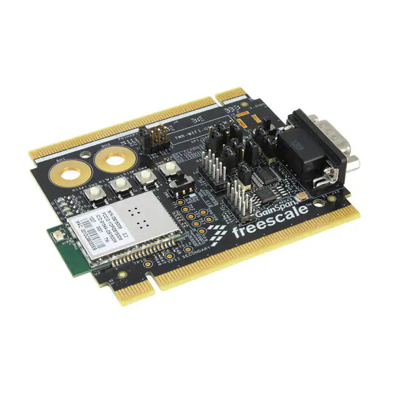
Configure Hardware To run the demos with the TWR-K60N512 hardware, and software projects, make certain that the jumpers and switches on the TWR-WIFI-GS1500M are in their default locations as shown below. Figure 1. TWR-WIFI-GS1500M Default Jumper Settings TWR-WIFI-G1011MI Lab Guide Page 4 of 11... - Page 5 Table 1. TWR-WIFI-GS1500M Default Jumper and Switch Settings Jumper Option Setting Description ELEV PWR Power from Tower System 3.3V Power Supply Input DC PWR Power from DC power jack (J2) GS1500M in standard "run" mode Mode Selection PRGM GS1500M in program mode Connect GS1500M interrupt to Tower IRQ_G (B56) Interrupt Connect GS1500M interrupt to Tower IRQ_E (B58)
-
Page 6: Configure Software
Configure Software This demo/lab walk-through guide uses the software listed below. Visit the links provided below to download and install the software if you do not already have it installed. 1. IAR for ARM – http://www.iar.com/en/Products/IAR-Embedded-Workbench 2. TWR-WIFI-GS1500M Demonstration Software for TWR-WIFI-GS1500M and TWR-K60N512 - http://www.freescale.com/TWR-WIFI-GS1500M TWR-WIFI-G1011MI Lab Guide Page 6 of 11... -
Page 7: Running The Demos
Running the Demos This reference code shows the following two demo’s that use Limited AP mode: 1) Embedded web server demo 2) Smart Phone Demo with service discovery (Bonjour) Below are steps to run the demos (web server and iOS) on the TWR-K60N512 with the TWR-WIFI- GS1500M: STEP 1: a) Download the TWR-WIFI-GS1500M Demonstration Software and unzip. - Page 8 STEP 2: Web – Server Demo Power on the Tower board and the TWR-WIFI-GS1500M device acts as an AP, generates its own Wi-Fi network and runs the embedded web Server Application. The Wi-Fi network SSID will be FS_APxxxxxx, where xxxxxx is last 6 digits of your board MAC address. Connect your PC or Tablet or HandHeld device Wi-Fi client to this AP (FS_APxxxxxx) network.
- Page 9 STEP 4: Smart Phone Demo Users may run the sensor demo using an iOS device (iPhone, iTouch or iPad) and see embedded discovery (bonjour) functionality of the TWR-WIFI-GS1500M module. Go to Apple iTUNES store and download and install the free GainSpan-Freescale Wi-Fi Sensor Application, if necessary. STEP 5: On the iOS device, enable Wi-Fi and connect to the SSID (FS_APxxxxxx) presented by the TWR board as described in Step 1.
- Page 10 STEP 6: Toggle the LED ON/OFF button to change the 4 LED’s status on the TWR-K60N512 board. Select the accelerometer sensor and rotate the tower to see the picture and accelerometer x, y, z change with the movement of the board. Adjust the potentiometer on the TWR-K60N512 board to control the light intensity on the smartphone.
-
Page 11: Troubleshooting
Troubleshooting If you are unable to communicate wirelessly from a PC to the Tower System, try the following: 1. Ensure the Tower system is assembled correctly. Each tower module has a primary and secondary card edge connector. The primary side must be connected to the Primary (or Functional in older systems) Elevator.
Need help?
Do you have a question about the Freescale TWR-WIFI-GS1500M and is the answer not in the manual?
Questions and answers